FIN1031MX中文资料
尼康 Z 7II Z 6II 数码照相机使用说明书

A安全须知
“安全须知”包括重要安全使用说明。在使用照相机之前,请务必先阅读本部分内
容。有关详细信息,请参阅“安全须知” (பைடு நூலகம் xxxv)。
❚❚ 锂离子电池组
锂离子电池组是GB31241-2014 《便携式电子产品用锂离子电池和电池 组安全要求》对产品的定义名称。本资料也存在对锂离子电池组简称为 “电池”的情形。
ii
想立即进行拍摄时
❚❚ 拍摄 (0 56)并查看 (0 69)照片
1 将模式拨盘旋转至b。
2 半按快门释放按钮 (即轻轻按下快门
释放按钮,且在按到一半时保持不 动)进行对焦。
3 在不松开快门释放按钮的情况下,完
全按下该按钮拍摄照片。
4 查看照片。
想立即进行拍摄时 iii
包装内物品
请确认您照相机的包装中是否包含下列所有物品。
照相机控制............................................................................................................. 13 取景器 ............................................................................................ 13
2 插入存储卡 (0 45)。
3 安装镜头 (0 50)。
• 将镜头上的白点与照相机机身上的白点 对齐 (q),然后按照图示方向旋转镜 头 (w)。
• 您可在照相机上安装挂带。有关详细信
息,请参阅“安装挂带” (0 37)。
4 开启照相机并设定日期和时间
(0 52)。
NVIDIA DGX SuperPOD用户指南说明书

NVIDIA DGX SuperPODUser GuideFeaturing NVIDIA DGX H100 and DGX A100 SystemsDU-10264-001 V32023-09-22BCM 10.23.09Contents1.NVIDIA DGX SuperPOD Overview (1)1.1Logical System Diagram (1)1.2Navigating the DGX SuperPOD (3)2.Workload Management (4)2.1Introduction (4)2.2Viewing System State (4)2.3Running Jobs (5)2.3.1Running Jobs with sbatch (5)2.3.2Running Jobs with srun (5)2.3.3Running Interactive Jobs with srun (6)2.4Specifying Resources when Submitting Jobs (6)2.5Monitoring Jobs (7)2.6Canceling Jobs (7)2.7Additional Resources (7)ing Containers (8)3.1Examples (8)1.NVIDIA DGX SuperPOD OverviewThe NVIDIA DGX SuperPOD™ is a multi-user system designed to run large artificial intelligence (AI) and high-performance computing (HPC) applications efficiently. While the system is composed of many different components, it should be thought of as a single system that can manage simultaneous use by many users and provide advanced access controls for queuing and scheduling resources. This ensures maximum performance, provides the tools for collaboration between users, and security controls to protect data and limit user interaction where necessary.This document does not cover information about the DGX SuperPOD that is specific to local policies or general Unix/Linux topics such as access, queuing, quotas, compiling, and editing and manipulating files and data.1.1Logical System DiagramFigure 1 provides a logical depiction of the DGX SuperPOD and all the components that enable it to work as a single multi-user system.Figure 1. Logical depiction of the DGX SuperPODThe boxes and connections in Figure 1 indicate that these components are not a part of the user-experience. Any lines that are dotted indicate that there is some connectivity between the two resources, but not necessarily every sub-component is connected. The optional jump box is an optional component outside of the DGX SuperPOD that enables remote access into it.Components from Figure 1 are further described in Table 1. Table 1. DGX SuperPOD components1.2Navigating the DGX SuperPODWhen a user first logs into the DGX SuperPOD, it will look like any other Linux system. They will be placed into their home directory and standard Linux commands will work.For example:# pwd/home/dgxuser# ls -al./bashrcIn addition, the high-speed file system will be available on the login nodes and all the compute nodes: # ls /lustre/fs1/projectsThe DGX SuperPOD is a collection of nodes and access is managed through the workload management system. The default workload management system is Slurm. Slurm enables submitting and managing jobs. See Workload Management for more details.2.Workload Management2.1IntroductionWorkload management is the submission and control of work on the system. Slurm is the workload management system used. Slurm is an open-source job scheduling system for Linux clusters, most frequently used for HPC applications. This guide covers some of the basics to get started using Slurm as a user on the DGX SuperPOD, including how to use Slurm commands such as sinfo, srun, sbatch, squeue, and scancel.The basic flow of a workload management system is that the user submits a job to the queue. A job is a collection of work to be executed. Shell scripts are the most common because a job often consists of many different commands.The system will take all the jobs submitted that are not yet running, look at the state of the system, and then map those jobs to the available resources. This workflow enables users to manage their work within large groups with the system determining the optimal way to order jobs for maximum system utilization (or other metrics that system administrators can configure).2.2Viewing System StateTo see all nodes in the cluster and their current state, ssh to the Slurm login node for your cluster and run the sinfo command:$ sinfoPARTITION AVAIL TIMELIMIT NODES STATE NODELISTbatch* up infinite 9 idle dgx[1-9]There are nine nodes available in this example, all in an idle state. If a node is busy, its state will change from idle to alloc when the node is in use:$ sinfoPARTITION AVAIL TIMELIMIT NODES STATE NODELISTbatch* up infinite 1 alloc dgx1batch* up infinite 8 idle dgx[2-9]2.3Running JobsThere are three ways to run jobs under Slurm. Jobs can be run with sbatch, where the work is queued in the system and control is returned to the prompt. The second is with srun, which will run the job on the system and the command will block while it waits to run and then runs to completion. The third way is to submit interactive jobs where srun is used to create the job, but shell access is given.2.3.1Running Jobs with sbatchWhile the srun command blocks any other execution in the terminal, sbatch can be run to queue a job for execution when resources are available in the cluster. Also, a batch job will enable several jobs to queue up and run as nodes become available. It is therefore good practice to encapsulate everything that must be run into a script and then execute with sbatch.$ cat script.sh#!/bin/bash/bin/hostname sleep 30$ sbatch script.sh2322$ squeueJOBID PARTITION NAME USER ST TIME NODES NODELIST(REASON)2322 batch script.sh user R 0:00 1 dgx1$ lsslurm-2322.out$ cat slurm-2322.outdgx12.3.2Running Jobs with srunTo run a job, use the srun command:$ srun hostnamedgx1This instructed Slurm to find the first available node and run hostname on it. It returned the result in our command prompt. It is just as easy to run a different command that runs a python script or a container using srun.Sometimes it is necessary to run on multiple systems:$ srun --ntasks 2 -l hostnamedgx1dgx22.3.3Running Interactive Jobs with srunWhen developing and experimenting, it is helpful to run an interactive job, which requests a resource and provides a command prompt as an interface to it:slurm-login:~$ srun --pty /bin/bashdgx1:~$ hostnamedgx1dgx1:~$ exitDuring interactive mode, the resource is being reserved for use until the prompt is exited. Commands can be run in succession.Before starting an interactive session with srun, it may be helpful to create a session on the login node with a tool like tmux or screen. This will prevent a user from losing interactive jobs if there is a network outage or the terminal is closed.2.4Specifying Resources when SubmittingJobsWhen submitting a job with srun or sbatch, request the specific resources needed for the job. Allocations are all based on tasks. A task is a unit of execution. Multiple GPUs, CPUs, or other resources can be associated to a task. A task cannot span a node. A single task or multiple tasks can be assigned to a node.As shown in Table 2 Resources can be requested several different ways.Table 2. Methods to specify sbatch and srun optionsWhile there are many combinations of options, here are a few common ways to submit jobs: >Request two tasks:srun -n 2 <cmd>>Request two nodes, eight tasks per node, and one GPU per task:sbatch -N 2 –-ntasks-per-node=8 –-gpus-per-task=1 <cmd>>Request 16 nodes, eight GPUs per node:sbatch -N 16 –-gpus-per-node=8 –-exclusive <cmd>2.5Monitoring JobsTo see which jobs are running in the cluster, use the squeue command:$ squeue -a -lTue Nov 17 19:08:18 2020JOBID PARTITION NAME USER STATE TIME TIME_LIMIT NODES NODELIST(REASON)9 batch bash user01 RUNNING 5:43 UNLIMITED 1 dgx110 batch Bash user02 RUNNING 6:33 UNLIMITED 2 dgx[2-3]To see just the running jobs for a particular user USERNAME:$ squeue -l -u USERNAMEThe squeue command has many different options available. See the man page for more details.2.6Canceling JobsTo cancel a job, use the scancel command:$ scancel JOBID2.7Additional ResourcesAdditional resources include:>S chedMD Slurm Quickstart Guide>L LNL Slurm Quickstart Guide>h ttps:///NVIDIA/deepops/blob/master/docs/slurm-cluster/slurm-usage.mding ContainersContainers provide a way to encapsulate all the software dependencies of an application and enable it to be deployed on different systems. Containers are the preferred way to run applications on the DGX SuperPOD.The DGX SuperPOD is deployed with two tools, Pyxis and Enroot, to help simplify the secure use of containers on the DGX SuperPOD. Pyxis extends the functionality of Slurm so that jobs can be launched directly into a container with srun. Enroot is a light-weight container-runtime that enables traditional container images to be run in unprivileged mode.3.1ExamplesHere are some example commands for working with user containers:>Submit a job to Slurm on a worker node.$ srun grep PRETTY /etc/os-releasePRETTY_NAME="Ubuntu 20.04.4 LTS">Submit a job to Slurm and launching it in a container.The --container-image option is used to specify which container to use.$ srun --container-image=centos grep PRETTY /etc/os-releasePRETTY_NAME="CentOS Linux 7 (Core)">Mount a file from the host and run the command on it from inside the container.$ srun --container-image=nvcr.io/nvidia/pytorch:22.12-py3 --container-mounts=/etc/os-release:/host/os-release grep PRETTY /host/os-releasepyxis: importing docker image: nvcr.io/nvidia/pytorch:22.12-py3pyxis: imported docker image: nvcr.io/nvidia/pytorch:22.12-py3PRETTY_NAME="Ubuntu 20.04.4 LTS">The --container-mounts option can be used to mount both files and directories into the container environment. Multiple options should be separated by commas.$ srun -N 2 --ntasks-per-node=1 --container-image=nvcr.io/nvidia/pytorch:22.12-py3 --container-mounts=/etc/os-release:/host/os-release grep PRETTY /host/os-releasepyxis: imported docker image: nvcr.io/nvidia/pytorch:22.12-py3pyxis: imported docker image: nvcr.io/nvidia/pytorch:22.12-py3>Submit the same command across two nodes, mounting the current directory as /work in the container.The full network name of the container is different. Enroot requires the separator between the network repository name (nvcr.io in this case) to be separated by a #, not a slash (/).srun -N 2 --ntasks-per-node=1 \--container-image=nvcr.io/nvidia/pytorch:22.12-py3 --container-mounts=$(pwd):/work \/bin/bash -c 'uname -n && cat /etc/os-release | grep PRETTY_NAME'dgx1PRETTY_NAME="Ubuntu 20.04.5 LTS"dgx2PRETTY_NAME="Ubuntu 20.04.5 LTS"Further resources are available at these links:>For a tutorial on running a multi-node Pyxis/Enroot BERT container, see this guide.>For a hello world tutorial on using MPI to run multi-gpu and multi-node jobs, see this guide.>For a tutorial on running a multi-node machine learning job using Dask on Slurm, see this guide. NVIDIA DGX SuperPOD User Guide DU-10264-001 V3 | 9NVIDIA Corporation | 2788 San Tomas Expressway, Santa Clara, CA 95051 NoticeThis document is provided for information purposes only and shall not be regarded as a warranty of a certain functionality, condition, or quality of a product. NVIDIA Corporation (“NVIDIA”) makes no representations or warranties, expressed or implied, as to the accuracy or completeness of th e information contained in this document and assumes no responsibility for any errors contained herein. NVIDIA shall have no liability for the consequences or use of such information or for any infringement of patents or other rights of third parties that may result from its use. This document is not a commitment to develop, release, or deliver any Material (defined below), code, or functionality.NVIDIA reserves the right to make corrections, modifications, enhancements, improvements, and any other changes to this document, at any time without notice. Customer should obtain the latest relevant information before placing orders and should verify that such information is current and complete.NVIDIA products are sold subject to the NVIDIA standard terms and conditions of sale supplied at the time of order acknowledgement, unless otherwise agreed in an individual sales agreement signed by authorized representatives of NVIDIA and customer (“Terms of Sale”). NVIDIA hereby expressly object s to applying any customer general terms and conditions with regards to the purchase of the NVIDIA product referenced in this document. No contractual obligations are formed either directly or indirectly by this document.NVIDIA makes no representation or warranty that products based on this document will be suitable for any specified use. Testing of all parameters of each product is not necessarily performed by NVIDIA. It is customer’s sole responsibility to evaluate and determine the applicability of any info rmation contained in this document, ensure the product is suitable and fit for the application planned by customer, and perform the necessary testing for the application to avoid a default of the application or the product. Weaknesses in customer’s product designs may affect the quality and reliability of the NVIDIA pro duct and may result in additional or different conditions and/or requirements beyond those contained in this document. NVIDIA accepts no liability related to any default, damage, costs, or problem which may be based on or attributable to: (i) the use of the NVIDIA product in any manner that is contrary to this document or (ii) customer product designs.No license, either expressed or implied, is granted under any NVIDIA patent right, copyright, or other NVIDIA intellectual property right under this document. Information published by NVIDIA regarding third-party products or services does not constitute a license from NVIDIA to use such products or services or a warranty or endorsement thereof. Use of such information may require a license from a third party under the patents or other intellectual property rights of the third party, or a license from NVIDIA under the patents or other intellectual property rights of NVIDIA.Reproduction of information in this document is permissible only if approved in advance by NVIDIA in writing, reproduced without alteration and in full compliance with all applicable export laws and regulations, and accompanied by all associated conditions, limitations, and notices.THIS DOCUMENT AND ALL NVIDIA DESIGN SPECIFICATIONS, REFERENCE BOARDS, FILES, DRAWINGS, DIAGNOSTICS, LISTS, AND OTHER DOCUMENTS (TOGETHER AND SEPARATELY, “MATERIALS”) ARE BEING PROVIDED “AS IS.” NVIDIA MAKES NO WARRANTIES, EXPRESSED, IMPLIED, STATUTORY, OR OTHERWISE WITH RESPECT TO THE MATERIALS, AND EXPRESSLY DISCLAIMS ALL IMPLIED WARRANTIES OF NONINFRINGEMENT, MERCHANTABILITY, AND FITNESS FOR A PARTICULAR PURPOSE. TO THE EXTENT NOT PROHIBITED BY LAW, IN NO EVENT WILL NVIDIA BE LIABLE FOR ANY DAMAGES, INCLUDING WITHOUT LIMITATION ANY DIRECT, INDIRECT, SPECIAL, INCIDENTAL, PUNITIVE, OR CONSEQUENTIAL DAMAGES, HOWEVER CAUSED AND REGARDLESS OF THE THEORY OF LIABILITY, ARISING OUT OF ANY USE OF THIS DOCUMENT, EVEN IF NVIDIA HAS BEEN ADVISED OF THE POSSIBILITY OF SUCH DAMAGES. Notwithstanding any damages that customer might incur for any reason whatsoever, NVIDIA’s aggregate and cumulative liability towards customer for the products described herein shall be limited in accordance with the Terms of Sale for the product.TrademarksNVIDIA, the NVIDIA logo, NVIDIA DGX and NVIDIA DGX SuperPOD are trademarks and/or registered trademarks of NVIDIA Corporation in the U.S. and other countries. Other company and product names may be trademarks of the respective companies with which they are associated.Copyright© 2023 NVIDIA Corporation. All rights reserved.。
MXconfig系列工业网络配置工具说明书
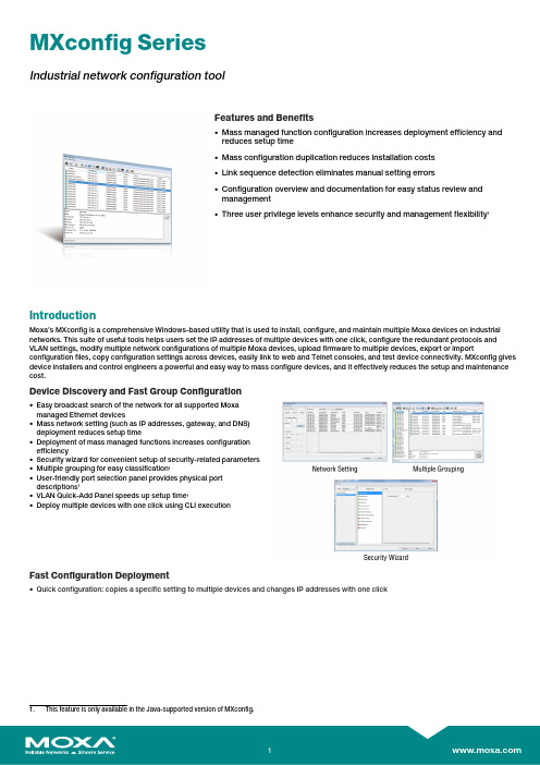
MXconfig SeriesIndustrial network configuration toolFeatures and Benefits•Mass managed function configuration increases deployment efficiency andreduces setup time•Mass configuration duplication reduces installation costs•Link sequence detection eliminates manual setting errors•Configuration overview and documentation for easy status review andmanagement•Three user privilege levels enhance security and management flexibility1IntroductionMoxa’s MXconfig is a comprehensive Windows-based utility that is used to install,configure,and maintain multiple Moxa devices on industrial networks.This suite of useful tools helps users set the IP addresses of multiple devices with one click,configure the redundant protocols and VLAN settings,modify multiple network configurations of multiple Moxa devices,upload firmware to multiple devices,export or import configuration files,copy configuration settings across devices,easily link to web and Telnet consoles,and test device connectivity.MXconfig gives device installers and control engineers a powerful and easy way to mass configure devices,and it effectively reduces the setup and maintenance cost.Device Discovery and Fast Group Configuration•Easy broadcast search of the network for all supported Moxamanaged Ethernet devices•Mass network setting(such as IP addresses,gateway,and DNS)deployment reduces setup time•Deployment of mass managed functions increases configurationefficiency•Security wizard for convenient setup of security-related parameters•Multiple grouping for easy classification1•User-friendly port selection panel provides physical portdescriptions1•VLAN Quick-Add Panel speeds up setup time1•Deploy multiple devices with one click using CLI executionFast Configuration Deployment•Quick configuration:copies a specific setting to multiple devices and changes IP addresses with one clickLink Sequence Detection•Link sequence detection eliminates manual configuration errorsand avoids disconnections,especially when configuringredundancy protocols,VLAN settings,or firmware upgrades for anetwork in a daisy-chain topology (line topology).•Link Sequence IP setting (LSIP)prioritizes devices and configuresIP addresses by link sequence to enhance deployment efficiency,especially in a daisy-chain topology (linetopology).Unlock Devices and User Privileges•Mass device unlocking and password file export for quick unlocks.•Three user privilege levels to enhance management flexibility and security:Admin,Supervisor,and Operator.2Configuration Overview and Documentation•Useful mass status overview and configuration check for eachmanaged function.•Generate reports on each managed function for multiple devices inthe network.2•Export multiple configuration files with flexible filenames and import multiple configuration files to multiple devices.•Export device list for easy backup,and import device list for quick searching2SpecificationsHardware RequirementsRAM2GB Hardware Disk Space10GB OSWindows 7(32/64-bit),Windows 10(32-64-bit),Windows Server 2012(32/64-bit)CPU 2GHz or faster dual-core CPUSupported DevicesAWK Products MXconfig Java Version:AWK-1121Series(v1.4or higher)AWK-1127Series(v1.4or higher)AWK-1131A Series(v1.11or higher)AWK-1137C Series(v1.3or higher)AWK-3121Series(v1.10or higher)AWK-3121-SSC-RTG Series(v1.4or higher)AWK-3121-M12-RTG Series(v1.4or higher)AWK-3131Series(v1.2or higher)AWK-3131-M12-RCC Series(v1.0or higher)AWK-3131A Series(v1.3or higher)AWK-3131A-RTG Series(v1.8or higher)AWK-4121Series(v1.10or higher)AWK-4131Series(v1.2or higher)AWK-4131A Series(v1.3or higher)AWK-5222Series(v1.7or higher)AWK-5232Series(v1.3or higher)AWK-6222Series(v1.7or higher)AWK-6232Series(v1.3or higher)EDR Products MXconfig Java Version:EDR-810Series(v3.2or higher)EDR-G902Series(v4.2or higher)EDR-G903Series(v4.2or higher)MXconfig Non-Java Version:EDR-810Series(v3.2or higher)EDR-G902Series(v4.2or higher)EDR-G903Series(v4.2or higher)EDR-G9010Series(v1.0or higher)EDS Products MXconfig Java Version:EDS-405A/408A Series(v3.1or higher)EDS-405A/408A-EIP Series(v3.1or higher)EDS-405A/408A-PN Series(v3.1or higher)EDS-405A-PTP Series(v3.3or higher)EDS-505A/508A/516A Series(v3.1or higher)EDS-510A Series(v3.1or higher)EDS-518A Series(v3.1or higher)EDS-510E/518E Series(v4.0or higher)EDS-528E Series(v5.0or higher)EDS-G508E/G512E/G516E Series(v4.0or higher)EDS-G512E-8PoE Series(v4.0or higher)EDS-608/611/616/619Series(v3.1or higher)EDS-728Series(v3.1or higher)EDS-828Series(v3.1or higher)EDS-G509Series(v3.1or higher)EDS-P510Series(v3.1or higher)EDS-P510A-8PoE Series(v3.1or higher)EDS-P506A-4PoE Series(v3.1or higher)EDS-P506E-4PoE Series(v5.5or higher)MXconfig Non-Java Version:EDS-405A/408A Series(v3.1or higher)EDS-405A/408A-EIP Series(v3.1or higher)EDS-405A/408A-PN Series(v3.1or higher)EDS-405A-PTP Series(v3.3or higher)EDS-505A/508A/516A Series(v3.1or higher)EDS-510A Series(v3.1or higher)EDS-518A Series(v3.1or higher)EDS-510E/518E Series(v4.0or higher)EDS-528E Series(v5.0or higher)EDS-G508E/G512E/G516E Series(v4.0or higher)EDS-G512E-8PoE Series(v4.0or higher)EDS-608/611/616/619Series(v3.1or higher)EDS-728Series(v3.1or higher)EDS-828Series(v3.1or higher)EDS-G509Series(v3.1or higher)EDS-P510Series(v3.1or higher)EDS-P510A-8PoE Series(v3.1or higher)EDS-P506A-4PoE Series(v3.1or higher)EDS-P506E-4PoE Series(v5.5or higher)ICS Products MXconfig Java Version:ICS-G7526/G7528Series(v3.1or higher)ICS-G7826/G7828Series(v3.1or higher)ICS-G7748/G7750/G7752Series(v3.1or higher)ICS-G7848/G7850/G7852Series(v3.1or higher)ICS-G7526A/G7528A Series(v4.0or higher)ICS-G7826A/G7828A Series(v4.0or higher)ICS-G7748A/G7750A/G7752A Series(v4.0or higher)ICS-G7848A/G7850A/G7852A Series(v4.0or higher)MXconfig Non-Java Version:ICS-G7826/G7828Series(v3.1or higher)ICS-G7748/G7750/G7752Series(v3.1or higher)ICS-G7848/G7850/G7852Series(v3.1or higher)ICS-G7526A/G7528A Series(v4.0or higher)ICS-G7826A/G7828A Series(v4.0or higher)ICS-G7748A/G7750A/G7752A Series(v4.0or higher)ICS-G7848A/G7850A/G7852A Series(v4.0or higher) IEX Products MXconfig Java Version:IEX-402Series(v1.0or higher)IEX-408E Series(v4.0or higher)MXconfig Non-Java Version:IEX-402Series(v1.0or higher)IEX-408E Series(v4.0or higher)IKS Products MXconfig Java Version:IKS-6726/6728Series(v3.1or higher)IKS-G6524Series(v3.1or higher)IKS-G6824Series(v3.1or higher)IKS-6728-8PoE Series(v3.1or higher)IKS-6726A/6728A Series(v4.0or higher)IKS-G6524A Series(v4.0or higher)IKS-G6824A Series(v4.0or higher)IKS-6728A-8PoE Series(v4.0or higher)MXconfig Non-Java Version:IKS-6726/6728Series(v3.1or higher)IKS-G6524Series(v3.1or higher)IKS-G6824Series(v3.1or higher)IKS-6728-8PoE Series(v3.1or higher)IKS-6726A/6728A Series(v4.0or higher)IKS-G6524A Series(v4.0or higher)IKS-G6824A Series(v4.0or higher)IKS-6728A-8PoE Series(v4.0or higher)ioLogik Products MXconfig Java Version:ioLogik E1200Series(v3.2or higher)ioThinx Products MXconfig Java Version:ioThinx4510Series(v1.3or higher)MDS Products MXconfig Java Version:MDS-G4012Series(v1.1or higher)MDS-G4020Series(v1.1or higher)MDS-G4028Series(v1.1or higher)MXconfig Non-Java Version:MDS-G4012Series(v1.1or higher)MDS-G4020Series(v1.1or higher)MDS-G4028Series(v1.1or higher)MDS-G4012-L3Series(v2.0or higher)MDS-G4020-L3Series(v2.0or higher)MDS-G4028-L3Series(v2.0or higher)MGate Products MXconfig Java Version:MGate MB3170/MB3270Series(v4.2or higher)MGate MB3180Series(v2.2or higher)MGate MB3280Series(v4.1or higher)MGate MB3480Series(v3.2or higher)MGate MB3660Series(v2.5or higher)MGate EIP3270Series(v2.0or higher)MGate5101-PBM-MN Series(v2.2or higher)MGate5102-PBM-PN Series(v2.3or higher)MGate5103Series(v2.2or higher)MGate5105-MB-EIP Series(v4.3or higher)MGate5108Series(v2.4or higher)MGate5208Series(v2.4or higher)MGate5109Series(v2.3or higher)MGate5111Series(v1.3or higher)MGate5114Series(v1.3or higher)MGate5118Series(v2.2or higher)MGate5217Series(v1.0or higher)NPort Products MXconfig Java Version:NPort S8000Series(v1.3or higher)NPort S9000Series(v1.0or higher)NPort5110Series(v3.8or higher)NPort5130/5150Series(v3.8or higher)NPort5000AI-M12Series(v1.4or higher)NPort5200Series(v2.10or higher)NPort5400Series(v3.13or higher)NPort5600Series(v3.9or higher)NPort5100A Series(v1.5or higher)NPort5200A Series(v1.5or higher)NPort5610-8-DT/5610-8-DT-J/5650-8-DT/5650I-8-DT/5650-8-DT-J Series(v2.6orhigher)NPort5610-8-DTL/5650-8-DTL/5650I-8-DTL Series(v1.5or higher)NPort IA5000Series(v1.6or higher)NPort IA5150A/IA5150AI/IA5250A/IA5250AI Series(v1.4or higher)NPort IA5450A/IA5450AI Series(v1.6or higher)NPort6000Series(v1.21or higher)PT Products MXconfig Java Version:PT-7528Series(v3.1or higher)PT-7710Series(v3.1or higher)PT-7728Series(v3.1or higher)PT-7828/7828-PTP Series(v3.1or higher)PT-G7509Series(v3.1or higher)PT-508/510Series(v3.1or higher)PT-G7728Series(v5.4or higher)PT-G7828Series(v5.4or higher)MXconfig Non-Java Version:PT-7528Series(v3.1or higher)PT-7710Series(v3.1or higher)PT-7728Series(v3.1or higher)PT-7828/7828-PTP Series(v3.1or higher)PT-G7509Series(v3.1or higher)PT-508/510Series(v3.1or higher)PT-G7728Series(v5.4or higher)PT-G7828Series(v5.4or higher)TAP Products MXconfig Java Version:TAP-213Series(v1.2or higher)TAP-323Series(v1.8or higher)TN Products MXconfig Java Version:TN-4500A Series(v3.5or higher)TN-5508/5510Series(v3.1or higher)TN-5516/5518Series(v3.1or higher)TN-5916Series(v1.2or higher)MXconfig Non-Java Version:TN-4500A Series(v3.5or higher)TN-4908Series(v1.0or higher)TN-5508/5510Series(v3.1or higher)TN-5516/5518Series(v3.1or higher)TN-5916Series(v1.2or higher)TN-G6500Series(v5.0or higher)VPort Products MXconfig Java Version:VPort26A-1MP Series(v1.2or higher)VPort36-1MP Series(v1.1or higher)VPort P06-1MP-M12Series(v2.2or higher)WAC Products MXconfig Java Version:WAC-1001Series(v2.1or higher)WAC-2004Series(v1.6or higher)©Moxa Inc.All rights reserved.Updated Jul30,2021.This document and any portion thereof may not be reproduced or used in any manner whatsoever without the express written permission of Moxa Inc.Product specifications subject to change without notice.Visit our website for the most up-to-date product information.。
英伟达nvidia NVS系列显卡

英伟达nvidia显卡quadro nvs 3100m参数表以及性能介绍2010-02-03 15:49:05采用nvidia(英伟达)cuda技术的nvidia(英伟达)nvs gpu(图形处理器)可最多搭载48个处理器核心,其大规模计算性能可以加速视频和图片编辑、分析以及地理影像处理,其速度比主流cpu最高提升10倍1nvidia quadro nvs架构如今扩展至商用笔记型计算机市场。
结合领先业界的硬件与软件,开发出一套完整的解决方案,nvidia quadro nvs笔记型计算机解决方案提供符合现今专业人士要求的可靠度、稳定度、易用性,并通过各种商业应用软件的兼容性测试。
不论您身处在办公室或外出,都能透过搭载nvidia quadro nvs 110m的笔记型计算机,随时随地执行各种商务应用。
gpu技术规格:cuada核心 16cuda并行处理器核心 72显存技术规格:显存总容量最大512mmb显存位宽 64-bit核心频率 (mhz) 1470支持的特性:directcomputer 支持opengl 支持directx 10 支持h.264、vc1、mpeg2 视频解码器支持nview显示器管理软件支持hdmi 7.1 声道高清音频支持purevideo高清1080p 支持支持hdmi 1.3 最大1920x1080支持pci express 2.0 支持支持vga 模拟显示器最大 2048x1536支持displayport 多显示器模式最大2560x1600hdcp 内容保护支持全规格蓝光解码支持- 使视频格式转换软件的速度实现最高达10倍的提升,例如elemental公司出品的badaboom软件、pegasys公司出品的tmpgenc 4.0软件。
另外,利用muvee reveal将影集打造成幻灯片电影,还可以利用motiondsp公司出品的vreveal软件自动提升视频片段的清晰度。
MX1031 V00使用说明书

MX1031/MX1031B 手机模块应用简要说明书一、 概述:二、 原理框图:三、 功能接口简介:3.1音频接口3.2LCD接口3.3I/O接口3.3.1充电功能3.3.2耳机功能3.3.3FM收音机天线3.3.4RS232接口3.3.5USB数据传输3.4马达接口3.5电池接口3.6天线馈点及RF测试点3.7蓝牙3.8摄像头接口3.9手电接口3.10DC充电接口3.11按键FPC接口3.12FM内置天线四、 模块版本信息五、 结构尺寸:一、 概述:本说明书简要介绍MX1031/MX1031B手机模块各接口定义及快速手机开发。
本说明书仅用于MX1031/MX1031B版。
三、 功能接口简介:3.1 音频接口:MX1031/MX1031B模块上共有一个焊线式受话器接口;一个弹片式受话器,示意图如下:3.2 LCD接口MX1031/MX1031B V00主板提供一个液晶屏MIPI接口,该接口支持串联LCD背光。
LCD接口定义:管脚号 管脚定义 说明1 LCD ID2 需兼容不同屏时ID1、ID2要不同电平组合2 VDD283 VDD_IO 2.8V/1.8V,主板接1.8V4 LCD ID1 需兼容不同屏时ID1、ID2要不同电平组合5 RSET 复位6 GND7 LPTE 同步信号8 NC9 GND10 LED_N 串联背光负板11 LED_P 串联背光正板12 LED_N 串联背光负板13 LED_P 串联背光正板14 GND15 LMIPI_D0N16 LMIPI_D0N17 GND18 LMIPI_CN19 LMIPI_CP20 GND21 LMIPI_D1N 如果液晶屏只需一路MIPI,此管脚悬空22 LMIPI_D1P 如果液晶屏只需一路MIPI,此管脚悬空23 GND3.3主板与按键小板FPC连接接口MX1031/MX1031 V00主板支持小板FPC扩展,支持的功能:双喇叭,马达,MIC,23个按键,3路按键背光灯(可做指示灯)。
MX技术键盘:长寿、精细操控的高级键盘说明书

2 years
Last update: 26 March 2004
Order description
Order number Colour
G80-3000LPMxx-0 G80-3000LQMxx-0 G80-3000LSMxx-0 G80-3000LUNxx-0
The manufacturer accepts no liability for errors or non-availability, and reserves the right to change specifications without prior notice. Technical data relate to product specifications only. Features may differ from those described. Only drawings combined with product specifications shall be deemed binding.
Classic Line
G80-3000
Standard keyboard
Key benefits MX technology Perfect key feeling The timeless keyboard for high-volume
data input and the most demanding requirements.
Weight:
approx. 1400 g (without packaging) approx. 1620 g (with packaging)
Dimensions:
approx. 470 x 195 x 44 mm (keyboard) approx. 500 x 255 x 50 mm (packaging)
黑铜 C310-M C320-M USB线头耳机用户指南说明书

Blackwire™ C310-M/ C320-MUSB Corded HeadsetUser GuideContentsIntroduzione3Requisiti di sistema3Ulteriori informazioni3Contenuto della confezione4Caratteristiche essenziali della cuffia5Come indossare la cuffia6Regolazione dell'archetto6Posizionamento dell'asta portamicrofono 6Regolazione dell'asta portamicrofono6Uso quotidiano7Alimentazione dell'auricolare7Chiamate in entrata/in uscita7Regolazione del volume nella cuffia7Esclusione del microfono8Risoluzione dei problemi9Cuffia911Congratulazioni per l'acquisto di questo prodotto Plantronics. La presente guida contiene istruzioni per la configurazione e l'uso del dispositivo Blackwire C310-M/C320-M headset..Prima di procedere all'installazione e all'utilizzo, consultare la Guida rapida per importanti istruzioni sulla sicurezza del prodotto.Computer•Sistemi operativi supportati: Windows ® 7, Windows XP ®, Windows Vista ®•Processore: Pentium ® da 400 MHz o equivalente (minimo); Pentium da 1 GHz o equivalente (consigliato)•RAM: 96 MB (min.); 256 MB (consigliato)•Disco rigido: 280 MB (min.); 500 MB o superiore (consigliato)•Microsoft Windows XP - Service Pack 3 (SP3) o successivo (consigliato) Microsoft Windows Vista - Service Pack 1 (SP1) o successivo (consigliato)Display•Almeno 800 x 600, a 256 colori•1024 x 768 con modalità video a colori, 32 bit (consigliato)Browser•Internet Explorer ® 6 o superiore installato sul sistema (necessario)Visitare il nostro sito Web /support per supporto tecnico, comprese le domande frequenti e le informazioni sulla compatibilità e l'accessibilità.IntroduzioneRequisiti di sistemaUlteriori informazioniBlackwire C310Blackwire C320Contenuto della confezionePulsante di risposta/fine chiamata*Consente di rispondere/terminare unachiamataChiamata in arrivoLampeggia in verdeChiamata in corsoVerde fissoPulsante di aumento del volumeConsente di aumentare il volume di ascoltoPulsante di diminuzione del volumeConsente di diminuire il volume di ascoltoPulsante di esclusione/riattivazionemicrofonoConsente di escludere/riattivare ilmicrofono della cuffiaRosso fisso quando il microfono è disattivato* Si richiede il software Plantronics. Il software Plantronics consente le funzioni di controllo chiamatecompresi i controlli di risposta/fine chiamata.Caratteristiche essenziali della cuffiaAllungare o accorciare la barra fino ad ottenere il massimo comfort. I cuscinetti in schiumadovrebbero essere collocati comodamente al centro delle orecchie.La cuffia può essere indossata a sinistra o a destra.Ruotare l'asta portamicrofono per allinearla alla bocca.AVVERTENZA Per evitare di rompere l'asta, ruotarla di 180° o con un angolo superiore.Piegare delicatamente l'asta portamicrofono in avanti o indietro in modo che sia a circa due dita di distanza dall'angolo della bocca.Come indossare la cuffiaRegolazione dell'archettoPosizionamento dell'astaportamicrofonoRegolazione dell'astaportamicrofonoLa cuffia USB si accende automaticamente al momento dell'inserimento nella porta USB delcomputer.Il controllo chiamate della cuffia è una funzionalità del software e dipende dalla compatibilitàcon il softphone utilizzato. Se non viene installato il software o non si dispone di un softphone compatibile, premere il pulsante di chiamata della cuffia, quindi rispondere/terminare/eseguire la chiamata utilizzando l'applicazione del softphone. Visitare il sito Web /software per maggiori informazioni.1Chiamate in entrata Premere il pulsante di risposta/fine chiamata sul controllo in linea dellacuffia per rispondere o terminare una chiamata.2Chiamate in uscita Per eseguire una chiamata in uscita, comporre il numero di telefonosull'applicazione del softphone.Uso quotidianoAlimentazione dell'auricolareChiamate in entrata/inuscitaRegolazione del volumenella cuffiaVolume di ascolto1Premere il pulsate di aumento del volume () sul controllo in linea della cuffia per aumentare il volume di ascolto.2Premere il pulsante di diminuzione del volume () sul controllo in linea della cuffia per diminuireil volume di ascolto.Volume di conversazionePer regolare il volume di ascolto sulla cuffia, utilizzare le impostazioni audio nel pannello di controllo/preferenze dell'audio sul computer.Per sistemi operativi Windows XP•Andare in Pannello di controllo > Suoni e periferiche audio > scheda Audio.Per sistemi operativi Windows Vista e Windows 7•Andare in Pannello di controllo > Suono > scheda Registrazione.Per Mac OS X•Selezionare il menu Apple > Preferenze di sistema > Suono > scheda Input.1Durante una chiamata, premere il pulsante di esclusione microfono sul controllo in linea dellacuffia per escludere il microfono. Con l'esclusione microfono attiva, il LED esclusione microfonoè rosso fisso (è ancora possibile udire il chiamante).2Per riattivare il microfono, premere nuovamente il pulsante di esclusione microfono.Esclusione del microfonoImpossibile sentire il chiamante.Il volume di ascolto è troppo basso. Premere il pulsante per laregolazione del volume sulla cuffia.La cuffia USB non è impostata come dispositivo audiopredefinito. Utilizzare le impostazioni audio nelle preferenze/nelpannello di controllo dell'audio per selezionare la cuffia comedispositivo audio predefinito.Per sistemi operativi Windows XP•Andare in Pannello di controllo > Suoni e periferiche audio >scheda Audio.•Selezionare la cuffia come dispositivo predefinito in"Riproduzione suoni".Per sistemi operativi Windows Vista e Windows 7•Andare in Pannello di controllo > Suono > scheda Output.•Evidenziare la cuffia, quindi selezionare Imposta predefinito >Dispositivo di comunicazione predefinito dall'elenco a discesa efare clic su OK.Per Mac OS X•Selezionare il menu Apple > Preferenze di sistema > Suono >scheda Output.•Selezionare la cuffia nella finestra "Seleziona dispositivo peruscita audio".Gli interlocutori non riescono a sentire.La cuffia è in modalità esclusione microfono. Premere il pulsante di esclusione microfono per riattivare il microfono.L'asta portamicrofono della cuffia non è posizionata correttamente. Regolare l'asta portamicrofono posizionandola all'altezza della bocca.La cuffia USB non è impostata come dispositivo vocale predefinito. Utilizzare le impostazioni audio nelle preferenze/nel pannello di controllo dell'audio per modificare il dispositivo di input.Per sistemi operativi Windows XP•Andare in Pannello di controllo > Suoni e periferiche audio > scheda Audio.•Selezionare la cuffia come dispositivo predefinito in "Registrazione audio".Per sistemi operativi Windows Vista e Windows 7•Andare in Pannello di controllo > Suono > scheda Registrazione.•Evidenziare la cuffia, quindi selezionare il pulsante Imposta predefinito e fare clic su OK.Per Mac OS X•Selezionare il menu Apple > Preferenze di sistema > Suono > scheda Input.•Selezionare la cuffia nella finestra "Seleziona dispositivo per entrata audio".L'audio nella cuffia è distorto. Sento un'eco nella cuffia.Abbassare il volume di ascolto del softphone fino a eliminare la distorsione.Risoluzione dei problemiCuffiaRegolare il volume sulla cuffia.La cuffia utilizzata per ascoltare la musica non funziona più.La cuffia USB viene impostata automaticamente come periferica audio predefinita in Windows. Utilizzare le impostazioni audio nelle preferenze/nel pannello di controllo dell'audio per modificare il dispositivo audio.Per sistemi operativi Windows XP•Andare in Pannello di controllo > Suoni e periferiche audio > scheda Audio.•In "Riproduzione suoni", modificare l'impostazione predefinita dalla cuffia al dispositivo scelto.Per sistemi operativi Windows Vista e Windows 7•Andare in Pannello di controllo > Suono > scheda Registrazione.•Evidenziare il dispositivo scelto, selezionare il pulsante Imposta predefinito e fare clic su OK.Per Mac OS X•Scegliere il menu Apple > Preferenze di Sistema e fare clic su Suono.•Fare clic su Output, quindi selezionare "Altoparlanti Interni" o il dispositivo scelto.La cuffia non risponde alle pressioni dei pulsanti.Quando il PC entra in modalità di standby o sospensione, la cuffia USB si spegne. Assicurarsi che il PC sia attivo.ULTERIORI INFORMAZIONI /supportPlantronics Inc.Plantronics BV345 Encinal Street Santa Cruz, CA 95060 Stati Uniti South Point Building C Scorpius 1402132 LR Hoofddorp Netherlands© 2011 Plantronics, Inc. Tutti i diritti riservati. Plantronics, il logo e Blackwire sono marchi o marchi registrati di Plantronics, Inc. Tutti gli altri marchi sono di proprietà dei rispettivi proprietari. Apple, iTunes e Mac sono marchi di Apple Inc., registrati negli Stati Uniti e in altri paesi. Microsoft, Vista, Windows e XP sono marchi di Microsoft Corporation negli Stati Uniti e in altri paesi. Pentium è un marchio registrato di Intel Corporation negli Stati Uniti e/o in altri paesi. Skype è un marchio di Skype Limited ed è utilizzato su licenza di Skype Limited.87395-15 (11.11)。
黑锋 C310-M C320-M USB串联耳机用户指南说明书

Blackwire™ C310-M/ C320-MUSB Corded HeadsetUser GuideContentsWillkommen3Systemanforderungen3Benötigen Sie weitere Hilfe?3Lieferumfang4Grundladen zum Headset5Headset tragen6Kopfbügel anpassen6Positionieren des Mikrofonarms 6Anpassen des Mikrofonarms6Tägliche Benutzung7Headset einschalten7Eingehende/ausgehende Anrufe7Headset-Lautstärke anpassen7Anruf stummschalten8Fehlerbehebung9Headset911Vielen Dank, dass Sie sich für den Kauf eines Plantronics Produkts entschieden haben. Dieses Benutzerhandbuch enthält Anweisungen zur Installation und Verwendung des Blackwire C310-M/C320-M headset..Lesen Sie vor der Installation oder Verwendung des Produkts die wichtigen Sicherheitsinformationen in der Kurzanleitung zu diesem Thema durch.Computer•Unterstützte Betriebssysteme: Windows ® 7, Windows XP ®, Windows Vista ®•Prozessor: Pentium ®-Prozessor mit 400 MHz oder gleichwertig (mindestens); Pentium-Prozessor mit 1 GHz oder gleichwertig (empfohlen)•RAM: 96 MB (mindestens); 256 MB (empfohlen)•Festplatte: 280 MB (mindestens); 500 MB oder mehr (empfohlen)•Microsoft Windows XP-Service Pack 3 (SP3) oder höher (empfohlen) Microsoft Windows Vista-Service Pack 1 (SP1) oder höher (empfohlen)Display•Mindestens 800 x 600, 256 Farben •1024 x 768 High Color, 32 Bit (empfohlen)Browser•Internet Explorer ® V6 oder besser muss auf dem System des Nutzers installiert sein (erforderlich)Besuchen Sie unsere Website /support , um technischen Support sowie Zugriff auf Antworten auf häufig gestellte Fragen und Informationen zur Kompatibilität bzw.Verfügbarkeit zu erhalten.WillkommenSystemanforderungenBenötigen Sie weitereHilfe?Blackwire C310Blackwire C320LieferumfangTaste zur Gesprächsannahme/-beendigung*Beantwortet oder beendet AnrufeEingehender Anruf Blinkt grün Laufendes Gespräch Leuchtet grün aufTaste zum Erhöhen der LautstärkeHörlautstärke erhöhenTaste zum Verringern der LautstärkeHörlautstärke verringernTaste zum Stummschalten/Beenden der StummschaltungSchaltet das Mikrofon stumm/beendet die StummschaltungLeuchtet bei Stummschaltung rot auf* Plantronics Software erforderlich. Plantronics Software bietet Standardfunktionen zur Anrufsteuerung wie die Funktion für Gesprächsannahme/-beendigung.Grundladen zum HeadsetVerlängern oder verkürzen Sie das Band so, dass der Kopfbügel angenehm sitzt. DieSchaumstoff-Ohrkissen sollten bequem am Ohr anliegen.Dieses Headset kann sowohl links als auch rechts getragen werden.Drehen Sie den Mikrofonarm so, dass sich das Mikrofon direkt vor Ihrem Mund befindet.VORSICHT Stellen Sie den Mikrofonarm auf bis zu 180°, damit dieser nicht beschädigt wird.Positionieren Sie den Mikrofonarm vorsichtig so, dass er in einem Abstand von 3 cm zur Ecke Ihres Mundes zeigt.Headset tragenKopfbügel anpassenPositionieren des MikrofonarmsAnpassen des MikrofonarmsDas USB-Headset wird beim Einstecken in den USB-Anschluss des Computers automatischeingeschaltet.Die Gesprächskontrolle über das Headset ist eine Softwarefunktion, die ein kompatiblesSoftphone voraussetzt. Falls Sie die entsprechende Software noch nicht installiert haben oder nicht über ein kompatibles Softphone verfügen, drücken Sie zuerst die Gesprächstaste am Headset und beantworten/beenden/halten Sie das Gespräch über die Softphone-Anwendung.Weitere Informationen finden Sie auf /software .1Eingehende Anrufe Drücken Sie die Taste zur Gesprächsannahme/-beendigung an der Inline-Regelung des Headsets, um ein Gespräch anzunehmen oder zu beenden.2Ausgehende Anrufe Wählen Sie die gewünschte Telefonnummer über Ihre Softphone-Anwendung, um einen Anruf zu tätigen.Tägliche BenutzungHeadset einschaltenEingehende/ausgehendeAnrufeHeadset-LautstärkeanpassenHörlautstärke1Drücken Sie an der Inline-Regelung des Headsets auf die Taste zum Erhöhen der Lautstärke (),um die Lautstärke zu erhöhen.2Drücken Sie an der Inline-Regelung des Headsets auf die Taste zum Verringern der Lautstärke(), um die Lautstärke zu verringern.SprechlautstärkeUm die Headset-Lautstärkeregelung anzupassen, ändern Sie die Audioeinstellungen über die Sound-Steuerung/Einstellungen Ihres Computers.Windows XP-Betriebssysteme•1 Gehen Sie zu …Systemsteuerung“ > …Sounds und Audiogeräte“ > …Audio“.Windows Vista- und Windows 7-Betriebssysteme •Gehen Sie zu …Systemsteuerung“ > …Sound“ > …Aufnahme“.Mac OS X•Öffnen Sie das Apple-Menü > …Systemeinstellung“ > …Sound“ > …Aufnahme“.1Um während eines Anrufes die Stummschaltung zu aktivieren, drücken Sie auf dieStummschaltungstaste an der Inline-Regelung des Headsets. Bei Aktivierung leuchtet dieStummschaltungs-LED rot (Sie können den Anrufer weiterhin hören).2Um die Stummschaltung zu deaktivieren, drücken Sie die Stummschaltungstaste erneut.Anruf stummschaltenIch kann den Anrufer nicht hören.Die Hörlautstärke ist zu niedrig. Drücken Sie auf dem Headsetauf die Lautstärketaste, um die Lautstärke zu erhöhen.Das USB-Headset ist nicht als Standard-Audiogerät eingerichtet.Verwenden Sie die Audioeinstellungen Ihres Betriebssystems, umdas Headset von Plantronics als Standard-Audiogeräteinzustellen.Windows XP-Betriebssystem•Gehen Sie auf …Start“ > …Systemsteuerung“ > …Sounds undAudiogeräte“ > …Audio“•Wählen Sie ihr Headset als Standardgerät zur Audiowiedergabeaus.Betriebssysteme Windows Vista und Windows 7•Gehen Sie zu …Systemsteuerung“ > …Sound“ > …Wiedergabe“.•Markieren Sie das Headset, wählen Sie …Als Standard“ >…Standardgerät für die Kommunikation“ und klicken Sie auf …OK“.Mac OS X•Öffnen Sie das Apple-Menü > …Systemeinstellung“ > …Sound“ >…Wiedergabe“.•Wählen Sie Ihr Headset im Fenster …Gerät zur Audiowiedergabeauswählen“.Anrufer können mich nicht hören.Das Headset ist stummgeschaltet. Drücken Sie dieStummschaltung, um die Stummschaltung des Mikrofonsaufzuheben.Der Headset-Mikrofonarm befindet sich in der falschen Position.Richten Sie den Headset-Mikrofonarm zu Ihrem Mund hin aus.Das USB-Headset ist nicht als Standard-Sprachgeräteingerichtet. Verwenden Sie die Audioeinstellungen IhresBetriebssystems, um das Aufnahmegerät zu ändern.Windows XP-Betriebssystem•Gehen Sie auf …Start“ > …Systemsteuerung“ > …Sounds undAudiogeräte“ > …Audio“•Wählen Sie ihr Headset als Standardgerät zur Audioaufnahmeaus.Betriebssysteme Windows Vista und Windows 7•Gehen Sie zu …Systemsteuerung“ > …Sound“ > …Aufnahme“.•Markieren Sie das Headset, wählen Sie …Als Standard verwenden“,und klicken Sie auf …OK“.Mac OS X•Öffnen Sie das Apple-Menü> …Systemeinstellung“ > …Sound“ > …Aufnahme“.•Wählen Sie Ihr Headset im Fenster …Gerät zur Audioaufnahmeauswählen“.Die Audiowiedergabe über das Headset ist verzerrt.Ich kann im Headset ein Echo hören.Reduzieren Sie die Hörlautstärke an Ihrem Softphone, bis die Verzerrung nicht mehr zu hören ist.Passen Sie die Lautstärke am Headset an.FehlerbehebungHeadsetDas andere Headset, mit dem ich Musik gehört habe, funktioniert nicht mehr.Das USB-Headset richtet sich selbsttätig als Standard-Audiogerät in Windows ein. Verwenden Sie die Audioeinstellungen Ihres Betriebssystems, um das Audiogerät zu ändern.Windows XP-Betriebssystem•Gehen Sie auf …Start“ > …Systemsteuerung“ > …Sounds und Audiogeräte“ > …Audio“•Passen Sie unter …Stimmwiedergabe“ die Standardeinstellungen vom Headset an das Gerät Ihrer Wahl an.Betriebssysteme Windows Vista und Windows 7•Gehen Sie zu …Systemsteuerung“ > …Sound“ > …Aufnahme“.•Wählen Sie das entsprechende Gerät, klicken Sie auf …Als Standard“ und dann auf …OK“.Mac OS X•Öffnen Sie das Apple-Menü, wählen Sie …Systemeinstellung“ und klicken Sie auf …Sound“.•Klicken Sie auf …Wiedergabe“ und wählen Sie anschließend …Interner Lautsprecher“ oder das gewünschte Gerät.Mein Headset reagiert nicht auf das Drücken von Tasten.Wenn der PC in den Standby-Modus oder den Ruhezustand übergeht, ist das USB-Headset nicht mehr eingeschaltet.Überprüfen Sie, ob der PC eingeschaltet und aktiv ist.BENÖTIGEN SIE WEITERE HILFE? /supportPlantronics Inc.Plantronics BVGildenweg 7 50354 Hürth USA Southpoint, Building C Scorpius 1402132 LR Hoofddorp Niederlande© 2011 Plantronics, Inc. Alle Rechte vorbehalten. Der Name Plantronics, das Logo und Blackwire sind Marken oder eingetragene Marken von Plantronics, Inc. Alle anderen Markennamen sind Eigentum ihrer jeweiligen Besitzer. Apple, iTunes und Mac sind Marken von Apple Inc., eingetragen in den USA und anderen Ländern. Microsoft, Vista, Windows und XP sind Marken der Microsoft Corporation in den USA und anderen Ländern. Pentium ist eine Marke der Intel Corporation in den USA und/oder anderen Ländern. Skype ist eine Marke von Skype Limited und wird mit der Genehmigung von Skype Limited verwendet.87395-04 (11.11)。
- 1、下载文档前请自行甄别文档内容的完整性,平台不提供额外的编辑、内容补充、找答案等附加服务。
- 2、"仅部分预览"的文档,不可在线预览部分如存在完整性等问题,可反馈申请退款(可完整预览的文档不适用该条件!)。
- 3、如文档侵犯您的权益,请联系客服反馈,我们会尽快为您处理(人工客服工作时间:9:00-18:30)。
© 2001 Fairchild Semiconductor Corporation DS500507July 2001Revised July 2001FIN1031 3.3V LVDS 4-Bit High Speed Differential DriverFIN10313.3V LVDS 4-Bit High Speed Differential DriverGeneral DescriptionThis quad driver is designed for high speed interconnects utilizing Low Voltage Differential Signaling (LVDS) technol-ogy. The driver translates LVTTL signal levels to LVDS lev-els with a typical differential output swing of 350mV which provides low EMI at ultra low power dissipation even at high frequencies. This device is ideal for high speed trans-fer of clock and data.The FIN1031 can be paired with its companion receiver,the FIN1032, or any other Fairchild LVDS receiver.Featuress Greater than 400Mbs data rate s 3.3V power supply operations 0.4ns maximum differential pulse skew s 2.0ns maximum propagation delay s Low power dissipation s Power OFF protections Meets or exceeds the TIA/EIA-644 LVDS standard s Pin compatible with equivalent RS-422 and LVPECL devices s 16-Lead SOIC and TSSOP packages save spaceOrdering Code:Devices also available in T ape and Reel. Specify by appending the suffix letter “X” to the ordering code.Function TableH = HIGH Logic Level L = LOW Logic Level X = Don’t CareZ = High ImpedanceConnection DiagramPin DescriptionsOrder Number Package NumberPackage DescriptionFIN1031M M16A 16-Lead Small Outline Integrated Circuit (SOIC), JEDEC MS-012, 0.150" Narrow FIN1031MTCMTC1616-Lead Thin Shrink Small Outline Package (TSSOP), JEDEC MO-153, 4.4mm WideInputsOutputsEN EN D IN D OUT +D OUT −H X H H L H X L L H H X OPEN L H X L H H L X L L L H X L OPEN L H LHXZZPin Name DescriptionD IN1, D IN2, D IN3, D IN4LVTTL Data InputsD OUT1+, D OUT2+, D OUT3+, D OUT4+Non-Inverting Driver Outputs D OUT1−, D OUT2−, D OUT3−, D OUT4−Inverting Driver OutputsEN Driver Enable PinEN Inverting Driver Enable Pin V CC Power Supply GNDGround 2F I N 1031Absolute Maximum Ratings (Note 1)Recommended Operating ConditionsNote 1: The “Absolute Maximum Ratings ”: are those values beyond which damage to the device may occur. The databook specifications should be met, without exception, to ensure that the system design is reliable over its power supply, temperature and output/input loading variables. Fairchild does not recommend operation of circuits outside databook specification.DC Electrical CharacteristicsOver supply voltage and operating temperature ranges, unless otherwise specifiedNote 2: All typical values are at T A = 25°C and with V CC = 3.3V.Supply Voltage (V CC )−0.5V to +4.6V DC Input Voltage (V IN )@V CC ≥ 3V −0.5V to +6V @V CC = 0V−0.5V to +4.6V DC Output Voltage (V OUT )@V CC = 0V−0.5V to +4.6VDriver Short Circuit Current (I OSD )ContinuousStorage Temperature Range (T STG )−65°C to +150°CMax Junction Temperature (T J )150°CLead Temperature (T L )(Soldering, 10 seconds)260°CESD (Human Body Model)≥ 8000V ESD (Machine Model)≥ 600VSupply Voltage (V CC ) 3.0V to 3.6VInput Voltage (V IN )0 to V CCOperating Temperature (T A )−40°C to +85°CSymbol ParameterTest ConditionsMin Typ MaxUnits (Note 2)V OD Output Differential Voltage 250350450mV ∆V OD V OD Magnitude Change from 25mV Differential LOW-to-HIGH R L = 100Ω, Driver Enabled,V OS Offset VoltageSee Figure 11.1251.251.375V ∆V OS Offset Magnitude Change from 25mV Differential LOW-to-HIGH I OFF Power Off Output Current V CC = 0V, V OUT = 0V or 3.6V ±20µA I OS Short Circuit Output Current V OUT = 0V, Driver Enabled −6mA V OD = 0V, Driver Enabled±6V IH Input HIGH Voltage 2.0V CC V V IL Input LOW Voltage GND0.8V I IN Input CurrentV IN = 0V or V CC ±20µA I OZ Disabled Output Leakage Current EN = 0.8V, EN = 2.0V ±20µA V OUT = 0V or 4.7V I I(OFF)Power-OFF Input Current V CC = 0V, V IN = 0V or 3.6V ±20µA V IK Input Clamp Voltage I IK = −18 mA−1.5VI CCPower Supply CurrentNo Load, V IN = 0V or V CC , Driver Enabled 3.25mAR L = 100 Ω, Driver Disabled3.25R L = 100 Ω, V IN = 0V or V CC , Driver Enabled17.925C IN Input Capacitance 7pF C OUTOutput Capacitance4pFFIN1031AC Electrical CharacteristicsOver supply voltage and operating temperature ranges, unless otherwise specifiedNote 3: All typical values are at T A = 25°C and with V CC = 3.3V.Note 4: t SK(LH), t SK(HL) is the skew between specified outputs of a single device when the outputs have identical loads and are switching in the same direc-tion.Note 5: t SK(PP) is the magnitude of the difference in propagation delay times between any specified terminals of two devices switching in the same direction (either LOW-to-HIGH or HIGH-to-LOW) when both devices operate with the same supply voltage, same temperature, and have identical test circuits.Note 6: f MAX Criteria: Input t R = t F < 1 ns, 0V to 3V, 50% Duty Cycle; Output V OD > 250 mV, 45% to 55% Duty Cycle; all output channels switching in phase.Note 7: Test Circuits in Figure 2 and Figure 4 are simplified representations of test fixture and DUT loading.Symbol ParameterTest ConditionsMinTyp MaxUnits (Note 3)t PLHD Differential Propagation Delay 0.8 1.4 2.0ns LOW-to-HIGHt PHLD Differential Propagation Delay 0.8 1.4 2.0ns HIGH-to-LOWt TLHD Differential Output Rise Time (20% to 80%)R L = 100 Ω, C L = 10 pF,0.60.85 1.2ns t THLD Differential Output Fall Time (80% to 20%)See Figure 2 and Figure 3 (Note 7)0.60.851.2ns t SK(P)Pulse Skew |t PLH - t PHL |0.4ns t SK(LH)Channel-to-Channel Skew 0.3ns t SK(HL)(Note 4)t SK(PP)Part-to-Part Skew (Note 5) 1.0ns f MAX Maximum Frequency (Note 6)200275MHz t ZHD Differential Output Enable Time from Z to HIGH2.5 5.0ns t ZLD Differential Output Enable Time from Z to LOW R L = 100Ω, C L = 10 pF,2.7 5.0ns t HZD Differential Output Disable Time from HIGH to Z See Figure 4 and Figure 5 (Note 7)3.2 5.0ns t LZDDifferential Output Disable Time from LOW to Z3.45.0ns4F I N 1031FIGURE 1. Differential Driver DC Test CircuitNote A: All input pulses have frequency = 10 MHz, t R or t F = 1 ns Note B: C L includes all fixture and instrumentation capacitancesFIGURE 2. Differential Driver Propagation Delay andTransition Time Test CircuitFIGURE 3. AC WaveformsNote B: All input pulses have the frequency = 10 MHz, t R or t F = 1 ns Note A: C L includes all fixture and instrumentation capacitancesFIGURE 4. Differential Driver Enable andDisable Test CircuitFIGURE 5. Enable and Disable AC Waveforms FIN1031Physical Dimensions inches (millimeters) unless otherwise noted16-Lead Small Outline Integrated Circuit (SOIC), JEDEC MS-012, 0.150" NarrowPackage Number M16A6F I N 1031 3.3V L V D S 4-B i t H i g h S p e e d D i f f e r e n t i a l D r i v e rPhysical Dimensions inches (millimeters) unless otherwise noted (Continued)16-Lead Thin Shrink Small Outline Package (TSSOP), JEDEC MO-153, 4.4mm WidePackage Number MTC16Fairchild does not assume any responsibility for use of any circuitry described, no circuit patent licenses are implied and Fairchild reserves the right at any time without notice to change said circuitry and specifications.LIFE SUPPORT POLICYFAIRCHILD ’S PRODUCTS ARE NOT AUTHORIZED FOR USE AS CRITICAL COMPONENTS IN LIFE SUPPORT DEVICES OR SYSTEMS WITHOUT THE EXPRESS WRITTEN APPROVAL OF THE PRESIDENT OF FAIRCHILD SEMICONDUCTOR CORPORATION. As used herein:1.Life support devices or systems are devices or systems which, (a) are intended for surgical implant into the body, or (b) support or sustain life, and (c) whose failure to perform when properly used in accordance with instructions for use provided in the labeling, can be rea-sonably expected to result in a significant injury to the user. 2. A critical component in any component of a life support device or system whose failure to perform can be rea-sonably expected to cause the failure of the life support device or system, or to affect its safety or effectiveness.。