ASTM E111-04 杨氏弹性模量、正切模量和弦向模量的试验方法
实验二杨氏弹性模量的测定实验报告
实验二杨氏弹性模量的测定实验报告一、实验目的1、学会用伸长法测量金属丝的杨氏弹性模量。
2、掌握光杠杆测量微小长度变化的原理和方法。
3、学会用逐差法处理实验数据。
二、实验原理杨氏弹性模量是描述固体材料抵抗形变能力的物理量。
假设一根粗细均匀的金属丝,长度为 L,横截面积为 S,受到外力 F 作用时伸长了ΔL。
根据胡克定律,在弹性限度内,应力(F/S)与应变(ΔL/L)成正比,比例系数即为杨氏弹性模量 E,其表达式为:\E =\frac{F \cdot L}{S \cdot \Delta L}\在本实验中,F 由砝码的重力提供,S 可通过测量金属丝的直径 d计算得出(\(S =\frac{\pi d^2}{4}\)),ΔL 是微小长度变化量,难以直接测量,采用光杠杆法进行测量。
光杠杆是一个带有可旋转支脚的平面镜,其前足尖放在固定平台上,后足尖置于待测金属丝的测量端,平面镜与金属丝平行。
当金属丝伸长ΔL 时,光杠杆后足尖随之下降ΔL,带动平面镜转过一个小角度θ。
设从望远镜中看到的标尺刻度的变化为Δn,光杠杆常数(即光杠杆前后足尖的垂直距离)为 b,望远镜到平面镜的距离为 D,则有:\(\tan\theta \approx \theta =\frac{\Delta L}{b}\)\(\tan 2\theta \approx 2\theta =\frac{\Delta n}{D}\)由上述两式可得:\(\Delta L =\frac{b \cdot \Delta n}{2D}\)将其代入杨氏弹性模量的表达式,可得:\E =\frac{8FLD}{\pi d^2 b \Delta n}\三、实验仪器杨氏弹性模量测定仪、光杠杆、望远镜、标尺、砝码、千分尺、游标卡尺等。
四、实验步骤1、调整仪器调节杨氏弹性模量测定仪底座的水平调节螺丝,使立柱铅直。
将光杠杆放在平台上,使平面镜与平台面垂直,前、后足尖位于同一水平面内。
测定杨氏模量的方法
测定杨氏模量的方法嘿,咱今儿就来讲讲测定杨氏模量的方法。
你知道不,这杨氏模量可是个挺重要的东西呢!就好比是材料的一个特性标签。
那怎么来测定它呢?有一种常见的方法就是拉伸法。
想象一下,把一根材料就像拉面条一样慢慢拉长,然后观察它在这个过程中的变化。
通过测量材料在拉伸前后的一些数据,就能算出杨氏模量啦。
这就好像你要知道一个人的力气有多大,那就让他去举个重物,看看能举多重,不就心里有数了嘛!还有一种方法是弯曲法。
这就像是让材料“弯腰”,看看它在弯曲时的表现。
是不是挺有意思的?通过研究材料弯曲时的各种数据,也能得出杨氏模量呢。
这就好比你要了解一根扁担能承受多大压力,你让它挑点东西,看看它啥反应。
另外啊,动态法也不错。
就好像给材料来一场特别的“音乐会”,让它跟着振动起来,然后根据振动的情况来确定杨氏模量。
这就像听一个乐器发出的声音,你就能大概知道这个乐器的好坏一样。
每种方法都有它的特点和适用情况呢。
就像不同的工具,有的适合干精细活,有的适合干粗活。
那在实际测定的时候,可得根据具体情况来选择合适的方法呀。
要是选错了方法,那不就像拿着斧头去绣花,或者拿着绣花针去砍树,那可不行哟!而且啊,在测定的过程中,可得细心再细心。
稍微有点偏差,那结果可能就差之千里啦。
这就跟你走路一样,要是一步没走好,可能就摔个大跟头。
所以说,每一个步骤都要认真对待,不能马虎。
那你说,这测定杨氏模量重要不?当然重要啦!它能让我们更好地了解材料的性能,为各种工程和科学研究提供重要的数据支持呢。
就像医生了解病人的身体状况一样,我们也要清楚材料的“身体状况”呀。
总之呢,测定杨氏模量的方法有很多,但不管是哪种方法,都需要我们认真去对待,仔细去研究。
这样才能得到准确可靠的结果,才能让我们更好地利用材料,创造出更多更棒的东西来!你说是不是呀?。
杨氏模量的测量方法

杨氏模量的测量方法
杨氏模量,也称作弹性模量或静态弹性模量,是材料弹性变形的比例系数。
它指材料
在受到拉力或压力时,单位面积的应变量与该拉力或压力的比值。
杨氏模量的测量对于材
料的研究以及弹性力学理论的理解至关重要。
下面将介绍几种测量杨氏模量的方法。
一、拉伸方法
拉伸测试是测量杨氏模量的常用方法之一。
该测试需要使用试样机,常用的有万能试
验机和压力传感器等设备。
在测试过程中,材料试样在两个夹紧装置之间受力,一端固定,另一端施以拉力。
拉伸过程中,测量应变和应力,该过程中应变为线性关系,因此可以根
据弹性线来计算杨氏模量。
二、压缩法
另一种测量杨氏模量的方法是压缩法。
该方法的基本原理是在平行靠近的两个表面之
间应用压力,在材料中引起垂直于两个表面之间的应变。
试验时,当应变在弹性范围内时,应力随着应变的逐渐增大,并且这种关系是线性的。
可以根据测得的应力和应变值,用线
性拟合来获得杨氏模量。
三、扭转法
扭转法是另一种广泛使用的测量杨氏模量的方法。
在该方法中,试样被固定在一个端点,另一个端点受到了扭矩的作用。
随着扭矩的逐渐增大,材料发生弹性变形,并且该部
分变形与应力是成比例的。
通过测量材料的应变和应力,可以计算出杨氏模量。
值得注意的是,以上三种测量方法在测试过程中,需要严格控制测试环境,确保测试
时的误差最小,从而减小结果的偏差。
在采用这些方法进行测试时,还需要对试样的准备、尺寸和形状等方面的要求进行详细的了解并正确地操作机器。
测杨氏模量的方法
测杨氏模量的方法
哇塞,说到测杨氏模量的方法,那可真是有趣又重要呢!
首先呢,常见的测量杨氏模量的方法有拉伸法。
具体步骤就是先准备好一根均匀的金属丝,把它固定在支架上,然后在下端挂上砝码,通过测量金属丝在不同砝码重量下的伸长量,再利用相关公式就可以计算出杨氏模量啦。
这里面要注意的可不少哦!比如说金属丝一定要均匀,不然测量结果就不准确啦;还有测量伸长量的时候要精确到小数点后几位呢,可不能马虎呀!砝码的重量也要准确称取,不然也会影响结果哦。
然后说说过程中的安全性和稳定性吧。
在操作的时候可一定要小心,别被砝码砸到脚啦!支架也要稳稳当当的,不然金属丝掉下来可不是开玩笑的。
整个过程要保证稳定进行,不能有晃动或者干扰,不然测量数据就不可靠啦。
那这种方法有啥应用场景和优势呢?它可以用在各种材料的研究和测试中呀,比如金属材料、塑料等等。
它的优势就在于简单易懂,操作起来相对容易,而且测量结果也比较可靠呢。
我给你说个实际案例哈,就像在建筑领域,工程师们就会用这种方法来测试建筑材料的杨氏模量,确保建筑物的安全性和稳定性呀。
你想想,如果材料的杨氏模量不合适,那房子不就不安全啦?通过这种方法的实际应用,就能很好地保证建筑质量呢,效果那是杠杠的!
总之,测杨氏模量的方法真的超级重要,它能让我们更好地了解材料的性质,为各种领域的发展提供有力的支持呀!。
杨氏弹模量的测定

测量的准确性和可靠性。
03
杨氏弹模量测定的实验设备
弹性模量测定仪
弹性模量测定仪是用于测量材料弹性模量的专用 01 设备,其原理基于材料在受到一定应力作用下的
形变响应。
弹性模量测定仪通常由加载系统、测量系统和数 02 据采集系统组成,能够实现自动化测量和数据处
理。
弹性模量测定仪的精度和稳定性对实验结果的影 03 响较大,因此需要定期进行校准和维护。
传感器
01 传感器是用于测量材料形变和应力的器件,其精 度和稳定性对杨氏弹模量的测定结果具有重要影 响。
02 常用的传感器类型包括电阻式、电容式和光纤式 等,不同类型的传感器具有不同的测量原理和应 用范围。
02 在选择传感器时,需要考虑其测量范围、灵敏度、 线性度、重复性和稳定性等因素,以确保实验结 果的准确性和可靠性。
适用于某些特殊材料或不易进行直接拉伸或压缩 实验的材料,如陶瓷、玻璃等。
混合法
01
定义
混合法是结合直接法和间接法的方法,即先通过直接法测量材料的应力
-应变曲线,再利用间接法测量的物理量计算杨氏弹模量。
02
实验设备
需要使用材料试验机和相关的间接测量设备。
03
适用范围
适用于某些具有复杂性质的材料,如复合材料、纳米材料等,可以提高
误差来源
设备精度
实验设备的精度对杨氏模量的测定结果有直接影响。例如, 应变计的精度、测试机的分辨率等都可能引入误差。
操作不当
实验操作过程中的人为误差也是误差来源之一。例如,试 样安装的紧固程度、加载速度的控制等都可能影响实验结 果。
环境因素
环境因素如温度、湿度等也可能对实验结果产生影响。例 如,温度变化可能导致材料热胀冷缩,从而影响应变测量 结果。
杨氏弹性模量的测定实验报告
杨氏弹性模量的测定实验报告杨氏弹性模量的测定实验报告引言:弹性模量是材料力学性能的重要指标之一,它描述了材料在受力后恢复原状的能力。
杨氏弹性模量是最常用的弹性模量之一,它用来衡量材料在拉伸或压缩过程中的变形程度。
本实验旨在通过测量金属杆的伸长量和受力情况,来确定杨氏弹性模量。
实验装置和步骤:本实验使用的装置主要包括一根金属杆、一个测力计、一个游标卡尺和一个螺旋拉伸装置。
实验步骤如下:1. 将金属杆固定在螺旋拉伸装置上,并调整装置使其与地面平行。
2. 在金属杆上选择两个固定点,分别用游标卡尺测量它们的距离,并记录下来。
3. 在金属杆上选择一个测量点,用游标卡尺测量它距离固定点的距离,并记录下来。
4. 将测力计挂在金属杆上,使其与测量点对齐,并记录下测力计示数。
5. 逐渐旋转螺旋拉伸装置,使金属杆受到拉伸力,并记录下拉伸力和测量点的位移。
6. 根据测力计示数和位移的变化,计算金属杆的应力和应变。
实验结果和数据处理:根据实验步骤所得到的数据,我们可以计算出金属杆的应力和应变,并绘制应力-应变曲线。
然后,我们可以通过应力-应变曲线的斜率来计算杨氏弹性模量。
在实验中,我们选择了铜杆进行测定。
测得的数据如下:固定点距离:L = 50 cm测量点距离固定点:x = 30 cm测力计示数:F = 100 N位移:ΔL = 0.5 cm根据上述数据,我们可以计算出金属杆的应力和应变:应力σ = F / A应变ε = ΔL / L其中,A是金属杆的横截面积。
通过测量金属杆的直径,我们可以计算出其横截面积。
假设金属杆的直径为d = 1 cm,则横截面积A = π * (d/2)^2 = 0.785 cm^2。
根据上述公式,我们可以计算出金属杆的应力和应变:应力σ = 100 N / 0.785 cm^2 ≈ 127.39 N/cm^2应变ε = 0.5 cm / 50 cm = 0.01接下来,我们可以绘制应力-应变曲线,并通过曲线的斜率来计算杨氏弹性模量。
杨氏模量的测量
杨氏模量的测定一、拉伸法测定金属丝的杨氏模量力作用于物体所引起的效果之一是使受力物体发生形变,物体的形变可分为弹性形变和塑性形变。
固体材料的弹性形变又可分为纵向、切变、扭转、弯曲,对于纵向弹性形变可以引入杨氏模量来描述材料抵抗形变的能力。
杨氏模量是表征固体材料性质的一个重要的物理量,是工程设计上选用材料时常需涉及的重要参数之一,一般只与材料的性质和温度有关,与其几何形状无关。
实验测定杨氏模量的方法很多,如拉伸法、弯曲法和振动法(前两种方法可称为静态法,后一种可称为动态法)。
本实验是用静态拉伸法测定金属丝的杨氏模量。
本实验提供了一种测量微小长度的方法,即光杠杆法。
光杠杆法可以实现非接触式的放大测量,且直观、简便、精度高,所以常被采用。
【实验目的】1. 掌握用光杠杆测量微小长度变化的原理和方法,了解其应用。
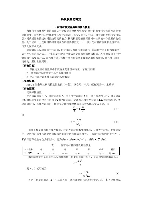
2. 掌握各种长度测量工具的选择和使用3. 学习用逐差法和作图法处理实验数据 【实验仪器】MYC-1型金属丝杨氏模量测定仪(一套),钢卷尺,米尺,螺旋测微计,重垂等 【实验原理】 一、杨氏弹性模量设金属丝的原长L ,横截面积为S ,沿长度方向施力F 后,其长度改变ΔL ,则金属丝单位面积上受到的垂直作用力F/S 称为正应力,金属丝的相对伸长量ΔL/L 称为线应变。
实验结果指出,在弹性范围内,由胡克定律可知物体的正应力与线应变成正比,即S F =LLY ∆ (1) 则Y =LL SF ∆ (2) 比例系数Y 即为杨氏弹性模量。
在它表征材料本身的性质,Y 越大的材料,要使它发生一定的相对形变所需要的单位横截面积上的作用力也越大。
一些常用材料的Y 值见表1。
Y 的国际单位制单位为帕斯卡,记为Pa (1Pa =12m N ;1GPa =910Pa )。
本实验测量的是钢丝的杨氏弹性模量,如果钢丝直径为d ,则可得钢丝横截面积S42d S π= 则(2)式可变为Ld FLY ∆=24π (3)可见,只要测出式(3)中右边各量,就可计算出杨氏弹性模量。
杨氏弹性模量的测定实验报告

杨氏弹性模量的测定实验报告
目录
1. 实验目的
1.1 实验原理
1.1.1 弹性模量的定义
1.1.2 杨氏弹性模量的计算公式
1.2 实验仪器
1.3 实验步骤
1.4 数据处理
1.5 实验结果与分析
1.6 实验结论
1. 实验目的
通过本实验,旨在掌握杨氏弹性模量的测定方法,了解弹性模量的物理意义,以及实验中应注意的问题。
1.1 实验原理
1.1.1 弹性模量的定义
弹性模量是材料抗拉伸性能的指标,是描述材料抵抗拉伸形变的能力的物理量。
1.1.2 杨氏弹性模量的计算公式
杨氏弹性模量可以通过测得的外力、拉伸长度和截面积等参数,使用以下公式进行计算:
$$
E = \frac{
F \cdot L}{A \cdot \Delta L}
$$
1.2 实验仪器
本实验所需的仪器包括拉伸试验机、标尺、外力计等。
1.3 实验步骤
1. 将试样放置于拉伸试验机上,并进行固定。
2. 施加外力,逐渐增加拉伸长度,记录相应数据。
3. 根据实验数据计算杨氏弹性模量。
1.4 数据处理
利用实验中测得的数据,按照计算公式进行处理,求解杨氏弹性模量。
1.5 实验结果与分析
根据实验测得的杨氏弹性模量数值,进行结果分析,比较实验数据之
间的差异,探讨可能的原因。
1.6 实验结论
总结实验过程中的得失,对实验结果进行概括,并讨论可能存在的误
差和改进方法。
- 1、下载文档前请自行甄别文档内容的完整性,平台不提供额外的编辑、内容补充、找答案等附加服务。
- 2、"仅部分预览"的文档,不可在线预览部分如存在完整性等问题,可反馈申请退款(可完整预览的文档不适用该条件!)。
- 3、如文档侵犯您的权益,请联系客服反馈,我们会尽快为您处理(人工客服工作时间:9:00-18:30)。
Designation:E111–97Standard Test Method forYoung’s Modulus,Tangent Modulus,and Chord Modulus1This standard is issued under thefixed designation E111;the number immediately following the designation indicates the year of original adoption or,in the case of revision,the year of last revision.A number in parentheses indicates the year of last reapproval.A superscript epsilon(e)indicates an editorial change since the last revision or reapproval.This specification has been approved for use by agencies of the Department of Defense.1.Scope1.1This test method2covers the determination of Young’s modulus,tangent modulus,and chord modulus of structural materials.This test method is limited to materials in which and to temperatures and stresses at which creep is negligible compared to the strain produced immediately upon loading and to elastic behavior.1.2Because of experimental problems associated with the establishment of the origin of the stress-strain curve described in8.1,the use of either initial tangent modulus(that is,the slope of the stress-strain curve at the origin)or secant modulus is not recommended and their determination is outside the scope of this test method.1.3This standard does not purport to address all of the safety concerns,if any,associated with its use.It is the responsibility of the user of this standard to establish appro-priate safety and health practices and determine the applica-bility of regulatory limitations prior to use.2.Referenced Documents2.1ASTM Standards:E4Practices for Force Verification of Testing Machines3 E6Terminology Relating to Methods of Mechanical Test-ing3E8Test Methods for Tension Testing of Metallic Materials3 E9Test Methods of Compression Testing of Metallic Ma-terials at Room Temperature3E21Test Methods for Elevated Temperature Tension Tests of Metallic Materials3E83Practice for Verification and Classification of Exten-someters3E231Method for Static Determination of Young’s Modu-lus of Metals at Low and Elevated Temperatures4N OTE1—General Considerations:While certain portions of the stan-dards and practices listed are applicable and should be referred to,the precision required in this test method is usually higher than that required in general testing.3.Terminology3.1Definitions:3.1.1accuracy—the degree of agreement between an ac-cepted standard value of Young’s modulus(the average of many observations made according to this method,preferably by many observers)and the value determined.3.1.1.1Increased accuracy is associated with decreased bias relative to the accepted standard value;two methods with equal bias relative to the accepted standard value have equal accu-racy even if one method is more precise than the other.See also bias and precision.3.1.1.2The accepted standard value is the value of Young’s modulus for the statistical universe being sampled using this method.When an accepted standard value is not available, accuracy cannot be established.3.1.2bias,statistical—a constant or systematic error in test results.3.1.2.1Bias can exist between the accepted standard value and a test result obtained from this test method,or between two test results obtained from this test method,for example, between operators or between laboratories.3.1.3precision—the degree of mutual agreement among individual measurements made under prescribed like condi-tions.3.1.4Young’s modulus—the ratio of tensile or compressive stress to corresponding strain below the proportional limit of the material(see Fig.1a).3.1.4.1tangent modulus—the slope of the stress-strain curve at a specified value of stress or strain(see Fig.1b).1This test method is under the jurisdiction of ASTM Committee E-28onMechanical Testing and is the direct responsibility of Subcommittee E28.03onElastic Properties and Definitions on Mechanical Testing.Current edition approved Apr.10,1997.Published November1997.Originallypublished as E111–st previous edition E111–82(1996)e1.2This test method is a revision of E111–61(1978),“Young’s Modulus at RoomTemperature”and includes appropriate requirements of E231–69(1975),“StaticDetermination of Young’s Modulus of Metals at Low and Elevated Temperatures”to permit the eventual withdrawal of the latter method.Method E231is under thejurisdiction of ASTM-ASME Joint Committee on Effect of Temperature on theProperty of Metals.3Annual Book of ASTM Standards,V ol03.01.4Discontinued,see1981Annual Book of ASTM Standards,V ol03.01.1Copyright©ASTM International,100Barr Harbor Drive,PO Box C700,West Conshohocken,PA19428-2959,United States.3.1.4.2chord modulus —the slope of the chord drawn be-tween any two specified points on the stress-strain curve,below the elastic limit of the material (see Fig.1c).3.2For definitions of other terms used in this test method,refer to Terminology E 6.4.Summary of Test Method4.1The test specimen is loaded uniaxially and load and strain are measured,either incrementally or continuously.The axial stress is determined,either incrementally or continuously,by dividing the load value by the specimen’s original cross-sectional area.The appropriate slope is then calculated from the stress-strain curve,which may be derived under conditions of either increasing or decreasing load (increasing from preload to maximum load or decreasing from maximum load to preload).5.Significance and Use5.1The value of Young’s modulus is a material property useful in design for calculating compliance of structural materials that follow Hooke’s law when subjected to uniaxial loading (that is,the strain is proportional to the applied force).5.2For materials that follow nonlinear elastic stress-strain behavior,the value of tangent or chord modulus is useful in estimating the change in strain for a specified range in stress. 5.3Since for many materials,Young’s modulus in tension is different from Young’s modulus in compression,it should be derived from test data obtained in the mode of stressing of interest.5.4The accuracy and precision of apparatus,test specimens,and procedural steps should be such as to conform to the material being tested and to a reference standard,if available.5.5Precise determination of Young’s modulus requires due regard for the numerous variables that may affect such deter-minations.These include (1)characteristics of the specimen such as orientation of grains relative to the direction of the stress,grain size,residual stress,previous strain history,dimensions,and eccentricity;(2)testing conditions,such as alignment of the specimen,speed of testing,temperature,temperature variations,condition of test equipment,ratio of error in load to the range in load values,and ratio of error in extension measurement to the range in extension values used in the determination;and (3)interpretation of data (see Section 9).5.6When the modulus determination is made at strains in excess of 0.25%,correction should be made for changes in cross-sectional area and gage length,by substituting the instantaneous cross section and instantaneous gage length for the originalvalues.FIG.1Stress-Strain Diagrams Showing Straight Lines Corresponding to (a )Young’s Modulus,(b )Tangent Modulus,and (c )ChordModulus5.7Compression results may be affected by barreling (see Test Methods E 9).Strain measurements should therefore be made in the specimen region where such effects are minimal.6.Apparatus6.1Dead Weights —Calibrated dead weights may be used.Any cumulative errors in the dead weights or the dead weight loading system shall not exceed 0.1%.6.2Testing Machines —In determining the suitability of a testing machine,it is advisable to calibrate the machine under conditions approximating those under which the determination is made.Corrections may be applied to correct for proven systematic errors in load.6.3Loading Fixtures —Grips and other devices for obtain-ing and maintaining axial alignment are shown in Test Methods E 8and E 9.It is essential that the loading fixtures be properly designed for use at the required temperature,and that they be properly maintained.6.4Extensometers —Class B-1extensometers as described in Practice E 83shall be used depending on the degree of precision required.Corrections may be applied for proven systematic errors in strain.Such corrections shall not beconsidered as changing the class of the extensometer.It is recommended that an averaging extensometer or the average of the strain measured by at least two extensometers arranged at equal intervals around the cross section be used.If two extensometers are used on other than round sections,they should be mounted at ends of an axis of symmetry of the section.If a load-strain recorder,strain-transfer device,or strain follower is used with the extensometer,they should be calibrated as a unit in the same manner in which they are used for determination of Young’s modulus.The gage length shall be determined with an accuracy consistent with the precision expected from the modulus determination and from the exten-someter used.N OTE 2—The accuracy of the modulus determination depends on the precision of the strain measurement.The latter can be improved by increasing the gage length.This may,however,present problems in maintaining specimen tolerances and temperature uniformity.6.5Furnaces or Heating Devices —When determining Young’s modulus at elevated temperature,the furnace or heating device used shall be capable of maintaining a uniform temperature in the reduced section of the test specimen so that a variation of not more than 61.5°C for temperatures up to and including 900°C,and not more than 63.0°C for temperatures above 900°C,occurs.(Heating by self-resistance is not recom-mended.)Temperature changes within the allowable limits should be minimized,since differences in thermal expansion between specimen and extensometer parts may cause signifi-cant errors in apparent strain.6.6Low-Temperature Baths and Refrigeration Equipment —When determining Young’s modulus at low temperatures,an appropriate low-temperature bath or refrigeration system is required to maintain the specimen at the specified temperature during testing.For a low-temperature bath,the lower tension rod or adapter may pass through the bottom of an insulated container and be welded or fastened to it to prevent leakage.For temperatures to about −80°C,chipped dry ice may be used to cool an organic solvent such as ethyl alcohol in the low-temperature bath.Other organic solvents having lower solidification temperatures,such as methylcyclohexane or isopentane,may be cooled with liquid nitrogen to temperatures lower than −80°C.Liquid nitrogen may be used to achieve a testing temperature of −196°C.Lower testing temperatures may be achieved with liquid hydrogen and liquid helium,but special containers or cryostats are required to provide for minimum heat leakage to permit efficient use of these coolants.When liquid hydrogen is used,special precautions must be taken to avoid explosions of hydrogen gas and air mixtures.If refrigeration equipment is used to cool the specimens with air as the cooling medium,it is desirable to have forced air circulation to provide uniform cooling.N OTE 3—At low temperatures,when using a coolant bath,immersion-type extensometers are recommended.7.Test Specimens7.1Selection and Preparation of Specimens —Special care shall be taken to obtain representative specimens which are straight and uniform in cross section.If straightening of the material for the specimen is required,the resultantresidualFIG.2Load-DeviationGraphstresses shall be removed by a subsequent stress relief heat treatment which shall be reported with the test results.7.2Dimensions—In general,it is recommended that the length of specimens(and radius offillets in the case of tension specimens)be greater than the minimum requirements for general-purpose specimens.In addition,the ratio of length to cross section of compression specimens should be such as to avoid buckling(see Test Methods E9).N OTE4—For examples of tension and compression specimens,see Test Methods E8and E9.7.3For tension specimens,the center lines of the grip sections and of the threads of threaded-end specimens shall be concentric with the center line of the gage section within close tolerances in order to obtain the degree of alignment required. If pin-loaded sheet-type specimens are used,the centers of the gripping holes shall be not more than0.005times the width of the gage section from its center line.For sheet-type specimens, it may be necessary to provide small tabs or notches for attaching the extensometer.N OTE5—The effect of eccentric loading may be illustrated by calcu-lating the bending moment and stress thus added.For a standard12.5-mm diameter specimen,the stress increase is1.5%for each0.025mm of eccentricity.This error increases to about2.5%per0.025mm for a9-mm diameter specimen and to about3.2%per0.025mm for a6-mm diameter specimen.7.4It is recommended that the length of the reduced section of tension specimens exceeds the gage length by at least twice the diameter or twice the width,that the length of compression specimens be in accordance with Test Methods E9,and that specimens be uniform in diameter or width throughout the gage length.N OTE6—If a general-purpose tension specimen such as those shown in Test Methods E8,having a small amount of taper in the reduced section is used,the average cross-sectional area for the gage length should be used in computing stress.7.5For compression specimens,the ends shall beflat, parallel and perpendicular to the lateral surfaces as specified in Test Methods E9.7.6This test method is intended to produce intrinsic mate-rials properties.Therefore,the specimen needs to be free of residual stresses,which may require a heat treatment to relieve the stresses in the material.The heat treatment procedure consists of annealing the specimen at Tm/3for30min(Tm is the melting point of the material in°K).The procedure must be mentioned in the report section.However,if the intent of the test is to verify the performance of a product,the heat treatment procedure may be omitted.This must be mentioned explicitly in the report section.8.Procedure8.1For most loading systems and test specimens,effects of backlash,specimen curvature,initial grip alignment,etc., introduce significant errors in the extensometer output when applying a small load to the test specimen.Measurements should therefore be made from a preload,known to be high enough to minimize these effects,to some higher load,still within either the proportional limit or elastic limit of the material.For linearly elastic materials,the slope of the straight-line portion of the stress-strain curve should be established between the preload and the proportional limit to define Young’s modulus.If the actual stress-strain curve is desired, this line can appropriately be shifted along the strain axis to coincide with the origin.For nonlinearly elastic materials the tangent or chord modulus may be established for stress values ranging from the appropriate preload to the elastic limit.8.2Measurement of Specimens—Make the measurements for the determination of average cross-sectional area at the ends of the gage length and at least at one intermediate e any means of measuring that is capable of producing area calculations within1%accuracy.8.3Alignment—Take special care to ensure as nearly axial loading as possible.The strain increments between the initial-load and thefinal-load measurement on opposite sides of the specimens should not differ from the average by more than 3%.For pin-loaded sheet-type tension specimens this degree of alignment can be attained if the gripping holes are located within the tolerance stated in7.3.8.4Soaking Time of Specimens at Testing Temperature—After the specimen to be tested has reached the testing temperature,it is necessary to maintain the specimen at the testing temperature for a sufficient length of time to attain equilibrium conditions in regard to the temperature of the specimen,extensometer expansion or contraction,and so forth, before applying the load.N OTE7—It is recommended that soak time and test temperature be1 h/in.(25mm)of specimen thickness or diameter.If the temperature of the system is not uniform by the time loading of the specimen is started,variations in thermal expansion will be reflected in the modulus line.Furthermore,fluctuations in temperature of the extensometer extensions,for example,during testing which result from cycling of the furnace temperature or changes in the level of the cooling bath may also effect the slope of the modulus line.8.5Speed of Testing—The speed of testing shall be low enough that thermal effects of adiabatic expansion or contrac-tion are negligible and that accurate determination of load and extension is possible,yet the speed shall be high enough that creep will be negligible.In loading with dead weights,avoid temporary overloading due to inertia of the weights.The strain rate should be reported.N OTE8—It is recommended that a minimum of three runs be made for each specimen.Care must be taken so that the proportional limit in the case of Young’s modulus,and the elastic limit in the case of the tangent or chord modulus,is not exceeded.Each of the three values or the average may be reported so long as the method for getting them is also reported. N OTE9—It is recognized that Young’s modulus,tangent modulus,or chord modulus for a given specimen may be determined along with yield strength and tensile strength using a single loading cycle.If modulus values are reported for tests made in this way,the fact that only one loading cycle was used should be stated.On the other hand,three cycles within the elastic region as recommended in Note8,can be made in determining the modulus,before straining the specimen into the plastic range to determine yield and tensile strengths.8.6Temperature Control—The average temperature over the specimen gage length should not deviate from the indicated nominal test temperature by more than62°C.In elevated-temperature tests,indicated temperature variations alongthegage length of the specimen should not exceed the following limits:up to and including 90061.5°C,above 90063.0°C.(See 6.5.)N OTE 10—The terms “indicated nominal temperature”or “indicated temperature”mean the temperature that is indicated by the temperature-measuring device using good pyrometric practice.5N OTE 11—It is recognized that actual temperatures may vary more than the indicated temperatures.The use of “indicated temperatures”for the limits of permissible variation in temperature are not to be construed as minimizing the importance of good practice and precise temperature control.All laboratories are obligated to keep the variation of indicated temperature from the actual temperature as small as is practical.Tempera-ture changes during the test,within the allowable limits,can cause significant strain errors due to differences in thermal expansion of the test specimen and extensometer parts.Temperature changes should be mini-mized while making strain measurements.8.7In low-temperature testing in which the bath is cooled with dry ice or in which a refrigeration system is used,the temperature of the medium around the specimen should be maintained at temperatures within 1.5°C of the specified temperature.Measurement of bath temperatures or of circulat-ing air from a refrigeration system may be done with a copper-constantan thermocouple or a suitable thermometer.If the specimen is submerged in a bath at the boiling point of the bath,sufficient soaking time (see Note 7)must be allowed to provide equilibrium conditions.Specimens tested in boiling liquids must meet the temperature control requirements speci-fied in 8.6.8.7.1Caution —The boiling point of a commercial liquid gas may not be the same as the published temperature for the pure liquid gas.8.8Temperature Measurement —The method of temperature measurement must be sufficiently sensitive and reliable to ensure that the temperature of the specimen is within the limits specified in 8.6and 8.7.Thermocouples in conjunction with potentiometers or millivolt meters are generally used to mea-sure temperatures.A discussion of temperature measurement and the use of thermocouples is given in Test Methods E 21.9.Interpretation of Data9.1If a plot of load-versus-extension is obtained by means of an autographic recorder,the value for Young’s modulus may be obtained by determining the slope of the line for loads less than the load corresponding to the proportional limit.Choice of the lower load point depends on the limitations set forth in 8.1.Young’s modulus is calculated from the load increment and corresponding extension increment,between two points on the line as far apart as possible,by use of the following equation:E 5S D pAoD ^S D cL oD(1)where:D p =load increment,A o =original cross-sectional area,D c =extension increment,and L o =original gage length.The precision of the value obtained for Young’s modulus will depend upon the precision of each of the values used in the calculation.It is suggested that the report include an estimate of the precision of the reported value of Young’s modulus based on the summation of the precisions of the respective values.When the modulus determination is made at strains in excess of 0.25%,corrections should be made for changes in cross-sectional area and gage length.9.2If the load-versus-extension data are obtained in numeri-cal form,the errors that may be introduced by plotting the data and fitting graphically a straight line to the experimental points can be reduced by determining Young’s modulus as the slope of the straight line fitted to the appropriate data by the method of least squares.This method also permits statistical study of the data and therefore an evaluation of the variability of the modulus within the stress range employed.The equation for Young’s modulus fitted by the method of least squares (all data pairs having equal weight)is:Young’s modulus,E 5~(~XY !2KX¯Y ¯!/~(X 22KX ¯2!(2)where:Y =applied axial stress,and X =corresponding strain.In terms of the measured load P i and measured original crosssectional area A o and gage length L o ,X =D cL o Y =D pA o Y¯=(Y K 5average of Y values X¯=(X K5average of X valueK =number of X,Y data pairs and (=sum from 1to K .The coefficient of determination,r 2,indicates the goodness of fit achieved in a single test.This coefficient is defined as follows:r 25S F(XY 2(X (YKG 2D ^S F(X 22~(X !2KGF(Y 22~(Y !2KG D(3)Values of r 2close to 1.00are desirable (see Table 1).5For further information on temperature control and measurement,see Panel Discussion on Pyrometric Practices,ASTM STP 178,1955.TABLE 1Fitting of Straight Lines Coefficient of Variation ofSlope (Percent)(V 1)Data Pairs(K )Sample Correlation Coefficients (r )0.900000.990000.999000.999900.999993648.4614.264.4761.4160.447527.98.22 2.580.8160.2581017.1 5.03 1.580.5000.1582011.4 3.35 1.050.3330.105309.1 2.690.840.2670.08450 6.9 2.050.640.2040.0641004.81.440.450.1420.045N OTE12—Many programmable calculators have built-in programs for calculating the slopes of straight linesfitted to a number of data pairs and their coefficient of determination.Details of the procedure may be found in standard textbooks on statistics or numerical analysis.6,7,8,9A coefficient of variation10can be assigned to the slope as follows(see Table1for representative values):V15100Œ1r21K22(4)where:V1=coefficient of variation,%N OTE13—It is recommended that the coefficient of variation be no larger than2%;however with care,values less than0.5%have been found to be achievable in aluminum alloys.9.3In determining the stress range for which data should be used in these calculations it is often helpful to examine the data by the strain deviation method.11,12,13For this test method, random variations in the data are considered as variations in strain,a trial modulus is chosen so that the deviations will be small,and the strain deviations are calculated as follows:Strain deviation=strain−(stress/trial modulus).These deviations are plotted to a large scale as abscissas with the stresses or loads as ordinates(Fig.2).The stress range for which data are used for obtaining Young’s modulus may be determined by examining the deviation graph with the aid of transparent paper on which three equally spaced lines are drawn as indicated in Fig.2.The spacing of the lines is determined in general by the random variations in strain deviation(extensometer least count).9.4Young’s modulus may also be determined by means of the deviation graph byfitting graphically a straight line to the appropriate points.From this line the deviation increment corresponding to a given stress increment can be read and substituted in the following equation:Young’s modulus5A/@~A/B!1C#(5) where:A=stress increment,B=trial modulus,andC=deviation increment.It is suggested that the strain corresponding to the spacing of the parallel lines be reported as measure of the variability of the data.9.5In the case of nonlinear elastic materials,the stress-strain curve may be obtained byfitting the load-versus-extension or load-versus-strain data pairs to a polynomial approximation7and the chord modulus obtained in calculating the slope between two specified sets of data pairs below the elastic limit on thefitting curve.The choice of the lower of the two sets of data pairs depends on the limitations set forth in8.1.9.6To establish confidence intervals for the regression line the following equation may be used:6I5tV1(6) where:I=percent of slope confidence interval,V1=coefficient of variation,expressed in percent(see9.2),andt=t−statistic from standard tables at K−2degrees of freedom and confidence level selected.Table2gives an example of representative values calculated using a95%confidence interval.10.Report10.1Report the following information:10.1.1Speciment Material—Describe the specimen mate-rial,alloy,heat treatment,mill batch number,grain direction, and so forth,as applicable.10.1.2Specimen Configuration—Include a sketch of the specimen configuration or reference to the specimen drawing.10.1.3Specimen Dimensions—State the actual measured dimensions for each specimen.10.1.4Test Fixture—Describe the testfixture or refer to fixture drawings.10.1.5Testing Machine and Extensometers—Include the make,model,serial number,and load range of the testing machine and the extensometers.10.1.6Speed of Testing—Record the test rate and mode of control.10.1.7Temperature—Record the temperature.10.1.8Stress-Strain Diagram—Include the stress-strain dia-gram showing both longitudinal and transverse strain with scales,specimen number,test data,rate,and other pertinent information.10.1.9Young’s Modulus,Tangent Modulus,Chord Modulus—Report the required value in accordance with Sec-tion9.6Youden,W.J.,Statistical Methods for Chemists,John Wiley and Sons,Inc., New York,NY,1951,Ch.S,pp.40–49.7Fröberg,C.E.,Introduction to Numerical Analysis,Second Edition,Addison Wesley Publishing Co.,Reading,MA,1969,p.335.8Experimental Statistics,NBS Handbook No.91.May be obtained fromSuperintendent of Natrella,M.G.,Documents,ernment Printing Office, Washington,DC20402.9Bowker,A.H.,and Lieberman,G.J.,Engineering Statistics,Prentice Hall, Englewood Cliffs,NJ,1959,pp.331–333.10Niemeier,B.,“Formability Testing for Precision and Accuracy,”Formability of Metallic Materials—2000A.D.,ASTM STP753,1979,pp.296–314.11Smith,C.S.,“Proportional Limit Tests on Copper Alloys,”Proceedings, ASTM,V ol40,1974,p.864.12McVetty,P.G.,and Mochel,N.L.,“The Tensile Properties of Stainless Iron and Other Alloys at Elevated Temperatures,”Transactions,Am.Soc.Steel Treating, V ol11,1927,pp.78–92.13Discussion by L.B.Tuckerman of paper by Templin,R.L.,“The Determi-nation and Significance of the Proportional Limit in the Testing of Metals,”Proceedings,ASTM,V ol29,Part II,1929,p.538.TABLE2Fitting of Straight Lines for95%Confidence Interval Percentage Values of Slope Confidence Interval(I)Data Pairs(K)t-StatisticSample Correlation Coefficients(r)0.990000.999000.999900.99999312.716180656.8617.965.75 3.18226.28.2 2.60.810 2.30611.6 3.6 1.20.420 2.1017.0 2.20.70.230 2.048 5.5 1.70.50.1750 2.011 4.1 1.290.410.129100 1.984 2.80.890.280.089。