Project IRQZ67 - DP 8
联想手机工程代码

┃ ┃ ┣━Cable 0---电缆
┃ ┃ ┣━SendKey 0
┃ ┃ ┗━Earphone 0---耳机
┃ ┣━ADC---模拟数字转换器(Analogue-Digital Converter)
┃ ┃ ┣━VBAT 3.79 V---电池电压
┃ ┃ ┃ ┣━[LEV 14] 146
┃ ┃ ┃ ┗━[LEV 15] 148
┃ ┃ ┣━Battery---电池
┃ ┃ ┃ ┣━LEV 1:3400000
┃ ┃ ┃ ┣━LEV 2:3400000
┃ ┃ ┃ ┣━LEV 3:3640000
┃ ┃ ┃ ┣━LEV 4:3650000
┃ ┃ ┣━BTemp 23.86 C---电池温度(会有小幅波动)
┃ ┃ ┣━VAUX 1.80 V---辅助电压(会有小幅波动)
┃ ┃ ┣━Current n/a---电流
┃ ┃ ┗━VChgr 0.70 V---充电电压(会有小幅波动)
┃ ┣━Set D160)
┃ ┃ ┃ ┣━音量3 (160)
┃ ┃ ┃ ┣━音量4 (240)
┃ ┃ ┃ ┣━音量5 (240)
┃ ┃ ┃ ┣━音量6 (240)
┃ ┃ ┃ ┗━16 Level Setting
┃ ┃ ┃ ┣━Max Analog Gain(242)
┃ ┃ ┣━MainLCD Contrast---主屏对比度
┃ ┃ ┃ ┣━[LEV 1] 120
┃ ┃ ┃ ┣━[LEV 2] 122
┃ ┃ ┃ ┣━[LEV 3] 124
┃ ┃ ┃ ┣━[LEV 4] 126
Lenovo Flex System x280 X6和x480 X6计算节点类型7196ADU和DD
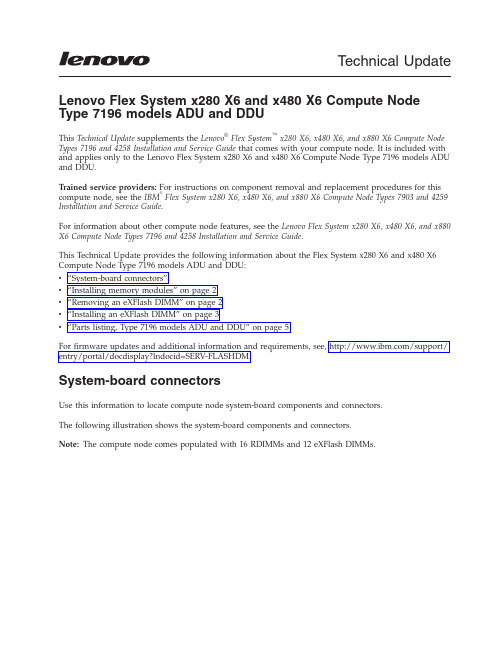
Technical Update Lenovo Flex System x280X6and x480X6Compute Node Type7196models ADU and DDUThis Technical Update supplements the Lenovo®Flex System™x280X6,x480X6,and x880X6Compute Node Types7196and4258Installation and Service Guide that comes with your compute node.It is included with and applies only to the Lenovo Flex System x280X6and x480X6Compute Node Type7196models ADU and DDU.Trained service providers:For instructions on component removal and replacement procedures for this compute node,see the IBM®Flex System x280X6,x480X6,and x880X6Compute Node Types7903and4259 Installation and Service Guide.For information about other compute node features,see the Lenovo Flex System x280X6,x480X6,and x880 X6Compute Node Types7196and4258Installation and Service Guide.This Technical Update provides the following information about the Flex System x280X6and x480X6 Compute Node Type7196models ADU and DDU:v“System-board connectors”v“Installing memory modules”on page2v“Removing an eXFlash DIMM”on page2v“Installing an eXFlash DIMM”on page3v“Parts listing,Type7196models ADU and DDU”on page5For firmware updates and additional information and requirements,see,/support/ entry/portal/docdisplay?lndocid=SERV-FLASHDM.System-board connectorsUse this information to locate compute node system-board components and connectors.The following illustration shows the system-board components and connectors.Note:The compute node comes populated with16RDIMMs and12eXFlash DIMMs.4Micro-1Micro-2Installing memory modulesThe compute node comes populated with 16GB RDIMMs.See “System-board connectors”on page 1for the locations of the DIMM connectors.See Table 1for the DIMM connectors populated with RDIMMs.Table 1.DIMM connectors populated with RDIMMs DIMM connector DIMM connector DIMM connector DIMM connector DIMM 1DIMM 4DIMM 7DIMM 10DIMM 15DIMM 18DIMM 21DIMM 24DIMM 25DIMM 28DIMM 33DIMM 36DIMM 37DIMM 40DIMM 45DIMM 48Removing an eXFlash DIMMUse this information to remove an eXFlash DIMM.Before you beginBefore you remove an eXFlash DIMM,complete the following steps:1.Review the safety information and installation guidelines in the Installation and Service Guide for yourcompute node.22.If the compute node is installed in a Flex System chassis,remove it(see the Installation and ServiceGuide for your compute node for instructions).3.Carefully lay the compute node on a flat,static-protective surface,orienting the compute node withthe bezel pointing toward you.ProcedureTo remove an eXFlash DIMM,complete the following steps.1.Remove the cover(see the Installation and Service Guide for your compute node for instructions).2.Remove the air baffle that is installed over the DIMM connector.3.Locate the DIMM connectors(see“System-board connectors”on page1for the locations of the DIMMconnectors).Determine which eXFlash DIMM you want to remove from the compute node.Attention:To avoid breaking the retaining clips or damaging the DIMM connectors,handle the clips gently.4.Make sure that both retaining clips on the DIMM connector from which you are removing theeXFlash DIMM are in the open position.5.Pull the eXFlash DIMM out of the connector.6.If you are not immediately replacing the eXFlash DIMM,install the air baffle.Attention:v Install the air baffles with the arrow indicating air flow direction pointing to the rear of thecompute node.v To maintain proper system cooling,do not operate the compute node without air baffles installed over the DIMM connectors.What to do nextIf you are instructed to return the eXFlash DIMM,follow all packaging instructions,and use any packaging materials for shipping that are supplied to you.Installing an eXFlash DIMMUse this information to install an eXFlash DIMM.Before you beginBefore you install an eXFlash DIMM,complete the following steps:1.Review the safety information and installation guidelines in the Installation and Service Guide for yourcompute node.2.Read the documentation that comes with the eXFlash DIMMs.3.If the compute node is installed in a Flex System chassis,remove it(see the Installation and ServiceGuide for your compute node for instructions).34.Carefully lay the compute node on a flat,static-protective surface,orienting the compute node withthe bezel pointing toward you.About this taskThe following notes describe information that you must consider when you install eXFlash DIMMs:v The compute node supports 12eXFlash DIMMs only.v Lockstep mode,mirrored-channel mode,and rank sparing are not supported when eXFlash DIMMs are installed.v eXFlash DIMMs operate at the same DIMM frequency as the speed of the RDIMMs installed in the compute node.v eXFlash DIMMs operate only at 1.5V .vFor more information about eXFlash DIMM requirements,see /support/entry/portal/docdisplay?lndocid=SERV-FLASHDM.Note:The amount of eXFlash DIMM storage that is displayed in the Setup utility might be different fromthe amount of eXFlash DIMM storage installed in the compute node.See Table 2for the DIMM connectors populated with eXFlash DIMMs.See “System-board connectors”on page 1for the locations of the DIMM connectors.Table 2.DIMM connectors populated with eXFlash DIMMs DIMM connector DIMM connector DIMM connector DIMM connector DIMM 2DIMM 5DIMM 8DIMM 11DIMM 14DIMM 17DIMM 20DIMM 23DIMM 26DIMM 29DIMM 44DIMM 47ProcedureTo install an eXFlash DIMM,complete the following steps:1.Remove the cover (see the Installation and Service Guide for your compute node for instructions).2.Read the documentation that comes with the eXFlash DIMM.3.Remove the air baffle installed over the DIMM connector.4.Locate the DIMM connectors (see “System-board connectors”on page 1for the locations of theDIMM connectors).Determine in which DIMM connector you want to install the eXFlash DIMM.5.Touch the static-protective package that contains the eXFlash DIMM to any unpainted metal surfaceon the Flex System chassis or any unpainted metal surface on any other grounded rack component in the rack in which you are installing the eXFlash DIMM for at least 2seconds;then,remove the eXFlash DIMM from the package.6.Make sure that both retaining clips on the DIMM connector are in the open position.47.Turn the eXFlash DIMM so that the eXFlash DIMM keys align correctly with the DIMM connectoron the system board.Attention:To avoid breaking the retaining clips or damaging the DIMM connector,handle the clips gently.8.Press the eXFlash DIMM into the DIMM connector.The retaining clips lock the eXFlash DIMM intothe connector.9.Make sure that the small tabs on the retaining clips engage the notches on the eXFlash DIMM.Ifthere is a gap between the eXFlash DIMM and the retaining clips,the eXFlash DIMM has not been correctly installed.Press the eXFlash DIMM firmly into the connector,and then press the retaining clips toward the eXFlash DIMM until the tabs are fully seated.When the eXFlash DIMM is correctly installed,the retaining clips are parallel to the sides of the eXFlash DIMM.10.Install the air baffle over the DIMM connector.Attention:v Install the air baffles with the arrow indicating air flow direction pointing to the rear of thecompute node.v To maintain proper system cooling,do not operate the compute node without air baffles installed over the DIMM connectors.What to do nextAfter you install the eXFlash DIMM,complete the following steps:1.Install the cover onto the compute node(see the Installation and Service Guide for your compute nodefor instructions).2.Install the compute node into the chassis(see the Installation and Service Guide for your compute nodefor instructions).Parts listing,Type7196models ADU and DDUThe following replaceable components are available for the Flex System x280X6and x480X6Compute Node Type7196models ADU and DDU.5Index Description Tier1CRUpart numberFRU partnumber1Top cover(when ordering this part,order the Label Kit part number00MP305)00AG9082Air baffle kit00AG905 3Flex System CN4054R10Gb Virtual Fabric Adapter00Y3309 4Memory,16GB2R x44Gbit DDR-31600MHz1.35V LP RDIMM46W06745Intel Xeon Processor E7-2870V215C2.3GHz30MB Cache1600MHz130W00Y39745Intel Xeon Processor E7-4890V215C2.8GHz37.5MB Cache1600MHz155W44X39986Not available7Bezel,front assembly kit00MP304 8SMP filler00AG911 9Center partition00AG904 10Solid state drive,200GB SAS2.5inch Enterprise MLC G3hot-swap00AJ208 11Hard disk drive backplane,SAS single2.5inch00Y3878 12Heat sink,microprocessor00AG887 Alcohol wipes59P47396Index Description Tier1CRUpart numberFRU partnumberThermal grease kit41Y9292Adapter connector retention kit00AG916Base assembly(includes chassis and system board)00MT370 Label kit00MP305Microprocessor installation tool94Y9971Miscellaneous parts kit00AG910CMOS battery,3.0volt(all models)33F8354CRM handle kit00AG915Rear bulkhead assembly full wide46M2833eXFlash DIMM,400GB SATA MLC00FE0067First Edition(January2015)Copyright Lenovo2015.Portions copyright IBM Corporation2015.LIMITED AND RESTRICTED RIGHTS NOTICE:If data or software is delivered pursuant a General Services Administration“GSA”;contract,use,reproduction,or disclosure is subject to restrictions set forth in Contract No. GS-35F-05925.Lenovo,the Lenovo logo,and Flex System are trademarks of Lenovo in the United States,other countries,or both. Printed in the USA(1P)P/N:00FH395。
设备管理器生成的错误代码说明

“解决方案”按钮:更新驱动程序
还有一种方法,可以使用“设备管理器”删除该设备,然后运行“控制面板”中的“添加新硬件”工具。
回到顶端
Code 4(代码 4)This device is not working properly because one of its drivers may be bad, or your registry may be bad.(Code 4)
To fix this problem, run Windows Setup again using your Windows CD-ROM.
其中,<name> 是找不到的系统 DevLoader。
“解决方案”按钮:无
? 如果这不是系统 DevLoader 并且找不到该 DevLoader(文件丢失),则会显示以下消息文本 This device is not working properly because Windows cannot find the file <name> that loads the drivers for the device.(Code 8)
回到顶端
Code 8(代码 8)对于此错误代码,可能显示几种不同的错误信息。此代码表示找不到该设备的 DevLoader。例如,该设备的 .inf 文件可能引用丢失或无效的文件。
此错误代码包括以下错误情况:
? 系统 DevLoader 是 Vmm32.vxd 的一部分,并通常以一个星号 (*) 开头。如果该 DevLoader 是系统 DevLoader,则会显示以下消息文本 This device is not working properly because Windows cannot load the file <name> that loads the drivers for the device.(Code 8)
MBR分区表
MBR分区表构成MBR分区表以80为起始,以55AA为结束,共64个字节,分为4个分区表,一个可启动分区和三个不可启动分区。
其结构如下:分区表一:第1个字节80(HEX) *可启动分区第2~4字节01/01/00(HEX)*开始磁头/开始扇区/开始柱面换算一下,二进制表示就是。
0000 0001/00000001/0000 0000(BIN)*开始磁头/开始扇区/开始柱面以下将使用16进制表示,不再换算成二进制!第五个字节0C *分区类型FAT32 NTFS为07,可自己变更第6~8字节FE/FF/FF *结束磁头/结束扇区/结束柱面第9~12字节00 00 00 3F *分区前的隐藏扇区63个隐藏扇区,此设计使0磁道使用0扇区,而1到62扇区不使用,减少读取,以此保护分区表,个人认为是个很不错的设计,不过很少有人知道这个。
第13~16字节5B 24 40 01 *分区大小20980827个扇区当然好要算上分区表的63个扇区一共20980889个扇区合10GB 公式为20980889*512/(1024^3)=10GB------------------------------------------------------我是一条分割线-----------------------------------------------分区表二:第17个字节00:不可启动分区第18~20字节开始磁头/开始扇区/开始柱面第21字节0F *分区类型为扩展分区第22~24字节结束磁头/结束扇区/结束柱面第25~28字节分区前的隐藏扇区第29~32字节分区大小分区表三,分区表四,以此类推,不再解释。
至于分区表的修改WinHex(DISKEDIT DOS下)是个不错的软件,了解了这些,就可以自己重建分区表了。
另:MBR是主分区表,误操作使MBR损坏时,DBR或者DBR备份应该没损坏,我们可以通过搜索55AA来获得DBR信息(往前找就行了),来寻找DBR从而了解更多信息(主要是分区大小和开始结束的扇区,磁头,柱头),来帮助我们重建分区表。
2440启动串口输出乱码问题

2440 移植2.6.30 (转)解压缩内核压缩文件后进入到目录中,然后修改Makefile,找到ARCH ?=CROSS_COMPILE ?=这两项,不修改这两项的话将会默认使用x86的配置,这里修改为ARCH ?= armCROSS_COMPILE ?= arm-linux-arm-linux- 是交叉编译器~ 这里我使用的交叉编译器为友善送的arm-linux-gcc-4.3.2.tgz,带EABI然后执行make menuconfig,然后进入System Type中看看是否为ARM体系~第一行为ARM system type 说明没错~ 然后在ARM system type中选择SamSung“S3C2410...”随后在下面出现的S3C2440 Machines中选择SMDK2440退出保存~ 执行make zImage出现ERRORdrivers/video/console/vgacon.c:510:error “PCIMEM_BASE undeclared”是在vgacon_startup中,vgacon是啥?~ 不认识~ 应该是不必要的东西~ 去掉它~vim drivers/video/console/Makefile在里面看见了这句obj-$(CONFIG_VGA_CONSOLE) += vgacon.o然后执行find ./ -name “Kconfig” | xargs grep “VGA_CONSOLE”看见config VGA_CONSOLE 在driver/video/console/Kconfig中也就是说在驱动->视频->终端中,执行make menuconfig在Device Drivers->Graphics Support->Console display driver support中发现了VGA text console去掉它,保存设置后再编译编译完成后将在arch/arm/boot中得到zImage文件使用SuperVivi的USB加载功能启动这个内核文件~ 得到下列输出zImage magic = 0x016f2818Setup linux parameters at 0x30000100linux command line is: "noinitrd root=/dev/mtdblock2 init=/linuxrc console=ttySAC0" MACH_TYPE = 1999NOW, Booting Linux......Uncompressing Linux........................................................................................................ done, booting the kernel.失败信息不够丰富~ 根据kasim大大的指点,在配置中进入Kernel hacking打开Kernel debugging和Kernel low-level debugging functions 还有Kernel low-level debugging messages via S3C UART保存后再编译运行zImage后得下列输出zImage magic = 0x016f2818Setup linux parameters at 0x30000100linux command line is: "noinitrd root=/dev/mtdblock2 init=/linuxrc console=ttySAC0" MACH_TYPE = 1999NOW, Booting Linux......Uncompressing Linux........................................................................................................ done, booting the kernel.Error: unrecognized/unsupported machine ID (r1 = 0x000007cf).Available machine support:ID (hex) NAME0000016a SMDK2440Please check your kernel config and/or bootloader.失败原来是machine的ID和Supervivi传递进来的ID不匹配~关于machine ID,可以参考一下这篇文章<2.6.18-2内核中对S3C2440的引导启动分析>虽然版本老了点,但是核心思想还是没有变vim arch/arm/mach-s3c2440/mach-smdk2440.c在最后一段有这句MACHINE_START(S3C2440 , ”SMDK2440”)这里S3C2440就是machine ID的代号~ 呢具体值是多少呢?~在arch/arm/tools/mach-types中s3c2440 ARCH_S3C2440 S3C2440 362原来我们的machine ID是362~呢bootloader传递进来的值是多少呢?~Error: unrecognized/unsupported machine ID (r1 = 0x000007cf).注意到没有?~ 0x7CF转换成10进制也就是1999修改mach-types中的对应项s3c2440 ARCH_S3C2440 S3C2440 1999虽然这样就和下面MINI2440的1999冲突了,但是只要不加入MINI2440的配置就没事修改后编译,再执行zImage后得下列输出zImage magic = 0x016f2818Setup linux parameters at 0x30000100linux command line is: "noinitrd root=/dev/mtdblock2 init=/linuxrc console=ttySAC0" MACH_TYPE = 1999NOW, Booting Linux......Uncompressing Linux........................................................................................................ done, booting the kernel.失败咦?~ 啥都没有?~ 最起码也应该有个乱码吧这时候我的第一反应是会不会没有跳入到start_kernel中所以马上编辑init/main.c,在start_kernel的前部加上printk(KERN_INFO “in start_kernel \n”);但是这个时候内核还没有初始化,所以printk是没有作用的~继续得到kasim大大的指点,编辑kernel/printk.c中的printk函数{va_list args;int r;#ifdef CONFIG_DEBUG_LLextern void printascii(const char *);char buff[256];#endifva_start(args, fmt);r = vprintk(fmt, args);#ifdef CONFIG_DEBUG_LLvsprintf(buff, fmt, args);#endifva_end(args);#ifdef CONFIG_DEBUG_LLprintascii(buff);#endifreturn r;}编译后执行zImage,得下列输出zImage magic = 0x016f2818Setup linux parameters at 0x30000100linux command line is: "noinitrd root=/dev/mtdblock2 init=/linuxrc console=ttySAC0" MACH_TYPE = 1999NOW, Booting Linux......Uncompressing Linux........................................................................................................ done, booting the kernel.<6>in start_kernel<6>Initializing cgroup subsys cpuset<6>Initializing cgroup subsys cpu<5>Linux version 2.6.30.3 (wolf@ubuntu) (gcc version 4.3.2 (Sourcery G++ Lite2008q3-72) ) #4 Wed Aug 5 16:54:49 CST 2009 ..................................................失败虽然正常输出了~ 有进入start_kernel~ 但是为什么之前每输出呢?~ 会不会是没有找到输出设备在输出中看到这行<5>Kernel command line: noinitrd root=/dev/mtdblock2 init=/linuxrc console=ttySAC0 console=ttySAC0 会不会是没有ttySAC0这个设备呢~ 在内核中搜索ttySAC 在driver/serial/samsung.c中得到对应项目这时候我猜想会不会没有加载samsung.c , 经过一轮Makefile和Kconfig的查询, 发现对应选项在Device Drivers->Character devices->Serial drivers中一看,原来根本就没有加载Samsung SoC serial support , 选成静态编译之后又出现了Support for console on Samsung SoC serial port ,就是它了,选上, 退出的时候顺便把Kernel low-level debugging functions给取消了否则我们设置的printk会自行输出,就不知道ttySAC有没有加载成功了编译后执行,得下列输出zImage magic = 0x016f2818Setup linux parameters at 0x30000100linux command line is: "noinitrd root=/dev/mtdblock2 init=/linuxrc console=ttySAC0" MACH_TYPE = 1999NOW, Booting Linux......Uncompressing Linux......................................................................................................... done, booting the kernel.w# DpñGpGp´ó70ÇC¼ØûÛ»›3ó•ó¸Û0ƒw#DpñGpGp´ó•tØ›•p¸›7¿³ó•\@û7¼¿[£¼Û3•¼ó;£¸ÀÛ;[7û;D°•D@GoGpGpíó•t›7•{ð#ßóÄ;›•770ÄÄ3Çß;GoDh}û7wœ´{…[ó7ûÛ›30°ôܸ‡#_sÄ;›•770Øijœ¼DG@ÁôÛ•ûÄ;•sÄ›£Ø›•DŽ³ÃÛ70ÄGpÁ4ßœ»ôGã›30³D˜ßF[s˜£ÀÛû70ÛD8ßÄ4G8ôGv£°ÇÃGpÍ´0ƒ†# DpñGš´;óC…[4¸F¸ÄÛtÜàGp}4GGÇ4tD@Ä38ÀGpGß ôØ Û›ŸÄÛD\Cûƒ£¸ƒ;7v›Ã30Ü›4Û´£ô¼;C3[;7ù³û770‡¸°[•4tD@Ä38ÀGpGß ´´p‡ƒ•ô¼Û7ŸtÛG»4œØ…Çpíƒw# .......................................失败但这说明ttySAC加载成功了~ 不过为什么是乱码呢?~这时候就需要对比友善的配置和我们的配置有什么不同了~打开友善送的linux-2.6.29,观察arch/arm/mach-s3c2440/mach-mini2440.c和我们的2.6.30.4下面的arch/arm/mach-s3c2440/mach-smdk2440.c有什么不同由于乱码主要是时钟问题,所以我们重点观察UART的设置和基本设置,其它什么NAND LCD 的就不看先修改smdk2440_uartcfgs[][2] = {.ulcon = 0x03,}修改s3c24xx_init_clocks(12000000);然后编译再运行,输出为zImage magic = 0x016f2818Setup linux parameters at 0x30000100linux command line is: "noinitrd root=/dev/mtdblock2 init=/linuxrc console=ttySAC0" MACH_TYPE = 1999NOW, Booting Linux......Uncompressing Linux......................................................................................................... done, booting the kernel.[ 0.000000] in start_kernel[ 0.000000] Initializing cgroup subsys cpuset[ 0.000000] Initializing cgroup subsys cpu ...........................最后为Kernel panic - not syncing: VFS: Unable to mount root fs on unknown-block(0,0)失败终于可以正常输出了,但是根文件系统挂载失败因为板子上的根文件系统为yaffs2 这时候内核还没有这个文件系统的支持,需要我们加上去拷贝友善的送的2.6.29下的fs/yaffs2目录到我们的fs目录下然后修改观察一下友善的送的2.6.29下的fs/Kconfig 和fs/Makefile和我们的有什么不同在我们的Kconfig中的source “fs/jffs2/Kconfig” 上面加上source “fs/yaffs2/Kconfig”在Makefile中的obj-$(CONFIG_FAT_FS) += fat/ 上面加上obj-$(CONFIG_YAFFS_FS) += yaffs2/然后在配置的File systems->Miscellaneous filesystems 中选上“YAFFS2 file system support” “Autoselect yaffs2 format” “Cache short names in RAM”然后编译运行,输出如下......................Kernel panic - not syncing: VFS: Unable to mount root fs on unknown-block(0,0)失败还是不行,往上看几行VFS: Cannot open root device "mtdblock2" or unknown-block(0,0)Please append a correct "root=" boot option; here are the available partitions:Kernel panic - not syncing: VFS: Unable to mount root fs on unknown-block(0,0)原来是没有可用的分区这个时候就要更正我们的NAND配置了还是对照友善送的linux-2.6.29,观察arch/arm/plat-s3c24xx/common-friendly-smdk.c来修改我们的arch/arm/plat-s3c24xx/common-smdk.c主要修改smdk_default_nand_part[]{[0] = {.name = “supervivi”,.size = 0x00060000,.offset = 0,},[1] = {.name = “Kernel”,.offset = 0x00060000,.size = 0x00200000,},[2] = {.name = “root”,.offset = 0x00260000,.size = 1024*1024*1024,},[3] = {.name = “nand”,.offset = 0x00000000,.size = 1024*1024*1024,}};编译后运行,输出VFS: Cannot open root device "mtdblock2" or unknown-block(0,0)Please append a correct "root=" boot option; here are the available partitions:Kernel panic - not syncing: VFS: Unable to mount root fs on unknown-block(0,0)失败还是不行,连最起码的分区都没有看见,会不会是MTD没有加载呢?~打开配置进入Device DriversMemory Technology Device ......... 前面是个M~ 说明这个模块是动态加载的,而我们编译的zImage里面只有静态模块将MTD选为静态加载,然后进入MTD配置中看看还有什么需要选的NAND Device Support 这个也是动态,选为静态加载进入NAND Device Support原来连NAND Flash support for S3C2410/S3C2440 SoC都没选,马上选为静态加载保存配置后编译运行,再运行输出如下:NAND device: Manufacturer ID: 0xec, Chip ID: 0xf1 (Samsung NAND 128MiB 3,3V 8-bit) Scanning device for bad blocksCreating 4 MTD partitions on "NAND 128MiB 3,3V 8-bit":0x000000000000-0x000000060000 : "supervivi"0x000000060000-0x000000260000 : "Kernel"0x000000260000-0x000040260000 : "root"mtd: partition "root" extends beyond the end of device "NAND 128MiB 3,3V 8-bit" -- size truncated to 0x7da00000x000000000000-0x000040000000 : "nand"mtd: partition "nand" extends beyond the end of device "NAND 128MiB 3,3V 8-bit" -- size truncated to 0x8000000 ...............................VFS: Cannot open root device "mtdblock2" or unknown-block(0,0)Please append a correct "root=" boot option; here are the available partitions:Kernel panic - not syncing: VFS: Unable to mount root fs on unknown-block(0,0)失败还是没有可用分区,虽然成功分辨了分区,但是没有加载成功,估计还是在MTD的模块选择上这时候需要对照友善的配置,经过对比,发现在友善的配置中静态编译了MTD中的下面3个模块Direct char device access to MTD devicesCommon interface to block layer for MTD …translation layers‟Caching block device access to MTD devices我们也选为静态编译保存配置后编译运行,输出如下List of all partitions:1f00 384 mtdblock0 (driver?)1f01 2048 mtdblock1 (driver?)1f02 128640 mtdblock2 (driver?)1f03 131072 mtdblock3 (driver?)No filesystem could mount root, tried: cramfsKernel panic - not syncing: VFS: Unable to mount root fs on unknown-block(31,2)分区加载成功了,但是文件系统却不能识别,我们之前不是已经加入了yaffs2么?~回到配置中再看,原来是动态编译,并没有真正进入到内核之中,选为静态编译~保存配置后编译,输出为yaffs: dev is 32505858 name is "mtdblock2"yaffs: passed flags ""yaffs: Attempting MTD mount on 31.2, "mtdblock2"yaffs: auto selecting yaffs2yaffs_read_super: isCheckpointed 0VFS: Mounted root (yaffs filesystem) on device 31:2.Freeing init memory: 128KKernel panic - not syncing: Attempted to kill init!失败依然错误,这个时候懵了,哪里错呢~ 没办法,只能对照着友善的配置一个个大模块对着来改当改到Kernel Features的时候错误消失了,原来需要选上Use the ARM EABI to compile the kernelAllow old ABI binaries to run with thie Kernel为什么呢?~ Google了一下,原来友善的根文件系统在编译的时候也启用了EABI特性,内核和文件系统需要对上文件系统用了EABI 内核也要用EABI 内核不用EABI 也只能读取不用EABI的文件系统选上这两项之后再编译,运行,输出如下yaffs: dev is 32505858 name is "mtdblock2"yaffs: passed flags ""yaffs: Attempting MTD mount on 31.2, "mtdblock2"yaffs: auto selecting yaffs2yaffs_read_super: isCheckpointed 0VFS: Mounted root (yaffs filesystem) on device 31:2.Freeing init memory: 128Kmount: mounting none on /proc/bus/usb failed: No such file or directoryhwclock: can't open '/dev/misc/rtc': No such file or directory[01/Jan/1970:00:00:13 +0000] boa: server version Boa/0.94.13[01/Jan/1970:00:00:13 +0000] boa: server built Mar 26 2009 at 15:28:42.[01/Jan/1970:00:00:13 +0000] boa: starting server pid=845, port 80open device leds: No such file or directoryTry to bring eth0 interface up......ifconfig: SIOCGIFFLAGS: No such deviceifconfig: SIOCSIFHWADDR: No such deviceifconfig: SIOCSIFADDR: No such deviceroute: SIOCADDRT: No such processDoneifconfig: SIOCSIFADDR: No such devicePlease press Enter to activate this console.[root@FriendlyARM /]#成功了,ls后输出如下bin home lost+found proc sys vardev lib mini2440 root tmp wwwetc linuxrc opt sbin usr不过ifconfig命令没有成功,继续来配置网卡对比友善的mach-mini2440.c文件,发现我们的mach-smdk2440.c中的smdk2440_devices[]数组并没有&s3c_device_dm9k这个结构,加上,追踪发现该数据结构在arch/arm/plat-s3c24xx/devs.c中,我们的devs.c中没有该数据结构的定义,加上#include <linux/dm9000.h>static struct resource s3c_dm9k_resource[] = {[0] = {.start = S3C2410_CS4,.end = S3C2410_CS4 + 3,.flags = IORESOURCE_MEM,},[1] = {.start = S3C2410_CS4 + 4,.end = S3C2410_CS4 + 4 + 3,.flags = IORESOURCE_MEM,},[2] = {.start = IRQ_EINT7,.end = IRQ_EINT7,.flags = IORESOURCE_IRQ | IRQF_TRIGGER_RISING,},};static struct dm9000_plat_data s3c_dm9k_platdata = {.flags = DM9000_PLATF_16BITONLY,};struct platform_device s3c_device_dm9k = {.name = “dm9000”,.id = 0;.num_resources = ARRAY_SIZE(s3c_dm9k_resource),.resource = s3c_dm9k_resource,.dev = {.platform_data = &s3c_dm9k_platdata,}};EXPORT_SYMBOL(s3c_device_dm9k);编译,出错,error : s3c_device_dm9k undeclared here找不到结构?~ 打开mach-smdk2440.c看看有什么头文件比较显眼的就是<plat/s3c2410.h><plat/s3c2440.h><plat/devs.h>,我们刚才编辑的文件是devs.c呢么devs.h的可能性较高,通过搜索,这个devs.h在/arch/arm/plat-s3c/include/plat/中,打开,BINGO,里面都是devs.c的数据定义加上我们的s3c_device_dm9kextern struct platform_device s3c_device_dm9k;再编译,通过了,不过这个时候先别急,我们只添加了设备,驱动有没有静态加载呢?~ 打开配置Device Drivers->Networks device support->Ethernet(10 or 100Mbit)DM9000 support没选上,马上选为静态编译保存配置,编译后运行,输出如下Try to bring eth0 interface up......说明DM9000配置成功使用ping命令进行测试,发现丢包率高达78%是不是驱动没设置好呢?~ 比较了一下友善的driver/net/dm9000.c和2.6.30.4的dm9000.c,发现明显不同直接拷贝友善的dm9000.c和dm9000.h过来编译后运行,顺利进入终端,然后运行PING丢包改善,基本无丢包我对这次内核移植的总结是:一步步来~ 先做好终端输出再挂载好根文件系统最后才考虑其它驱动的配置到此移植就基本结束了= 3=)/ 感谢阅读。
DDU6871 DW6851 DX6831 DLP Projector Remote Communi
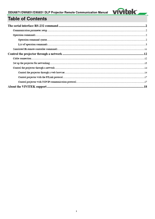
The serial interface RS-232 command (2)Communication parameter setup (2)Operation commands (2)Operation command syntax (2)List of operation commands (3)Simulated IR remote controller commands (11)Control the projector through a network (12)Cable connection (12)Set up the projector for networking (13)Control the projector through a network (14)Control the projector through a web browser (14)Control projector with the PJLink protocol (17)Control projector with TCP/IP communication protocol (17)About the VIVITEK support (18)This controller supports projectors with a RS-232 serial interface. There exist two types of serial commands:Operation command: Available menu options are INPUT, PICTURE, LAMP, ALIGNMENT, CONTROL, SERVICE, and OTHERS.Simulated IR remote controller commands: Controls projector with serial command analog IR remote controller and its control keys.Communication parameter setupYou can use the serial control command to input commands for projector control or retrieve its operational data through Windows client terminal software, e.g. Hyper Terminal, with ASCII characters.You need to set up the following communication parameters in advance:Item Parameter:Bit per Second 115200 (default), 57600, 38400, 19200, 14400, 9600, 4800, 2400, 1200bpsData Bit 8-bitParity NoneStop Bit 1Flow Control NonePort 7000Caution:The terminal software does not return every command input characterThe transmission performance varies with the matching length of RS-232 cable and transmission speed.Please select proper transmission from the OSD menu.Operation commandsOperation command syntaxAn operation command is prefixed by character "op", followed by control commands and settings separated by space blank [SP], and ended by carriage return pair "CR" and "ASCII hex 0D".Syntax of serial control commands: op[SP]<operation command>[SP]<Setting Value>[CR]op :A constant indicating this is an operation command.[SP] :Indicate one blank space.[CR] :Indicate the command ending carriage return pair "CR" and "ASCII hex 0D".Setting value : Settings of operation commandTypes of setup strings Characters of settings DescriptionQuery current setup ? Question mark "?" indicates querying current setup Setup = <settings> Syntax of settings: Symbol "=" suffixed with setupvaluesIncrease setup order of adjustment items + Some settings are changed in steps. Symbol "+"indicates changing one step upDecrease setup order of adjustment items - Some settings are changed in steps. Symbol "-"indicates changing one step downExecute operation command None Certain operation commands execute after inputwithout further setting or regulators. Examples:Control items Input command row Projector return messageQuery current brightnesssettingsop bright ? [CR] OP BRIGHT = 101Set up brightness op bright = 127 [CR] OP BRIGHT = 127Set up input signal source toHDMIop input.sel = 0 [CR] OP INPUT.SEL = 0Caution:When controlling the projector to execute multiple commands, make sure the return message of the last command is received before sending out the next one.List of operation commandsInputOSD function OperationcommandSettings/return values NoteInput Select input.sel ?= 0 = HDMI1 = DVI2 = VGA3 = Component / BNC4 = DisplayPort5 = Digital Do not apply when the project is in standby modea. Standby modeb. When the blank function is activatedTest Pattern pattern ?= 0 = Color Bar1 = Cross Hatch2 = Burst3 = Red (TI)4 = Green (TI)5 = Blue (TI)6 = WHITE (TI)7 = BLACK (TI)8 = HRamp (TI)9 = Red (uncorrected)10 = Green (uncorrected)11 = Blue (uncorrected)12 = White (uncorrected)13 = Black (uncorrected)14 = Off Do not apply when the project is in standby modeColor Space color.space ?= 0 = Auto1 = YcbCr (Rec. 601)2 = YPbPr (Rec. 709)3 = RGB-PC (0-255)4 = RGB-Video (16-235) Do not apply when the project is in standby mode or the input signal is not yet locked.Input Lock input.lock ?= 0 = Auto1 = 48 Hz2 = 50 Hz3 = 60 Hz Do not apply when the project is in standby mode or the input signal is not yet locked.Background no.signal ?= 0 = Logo1 = Blue2 = Black3 = White Do not apply when the project is in standby modeLAMPSOSD function OperationcommandSettings/return values NoteLamp Mode lamps ?= 0 = Dual1 = Lamp12 = Lamp23 = Singlea. Do not apply when the project is instandby modeb. Do not apply when the project is incooling or lighting up status.Please send control commandafter the said commands arecompleted.Lamp Power lamp.mode ?= 0 = Standard1 = Economy2 = Custom Power LevelDo not apply when the project is instandby modeCustom Lamp Power lamp.pwr ?= 0-31 (75 % ~ 100.0 %) Do not apply when the project is instandby modeHigh Altitude altitude ?= 0 = Off1 = OnDo not apply when the project is instandby modeLamp 1 Status lamp1.stat ? 0 = Off1 = On Do not apply when the project is in standby modeLamp 2 Status lamp2.stat ? 0 = Off1 = On Do not apply when the project is in standby modeALIGNMENTOSD function OperationcommandSettings/return values NoteProjection Mode proj.mode ?= 0 = Front1 = Rear2 = Ceiling + Front3 = Ceiling + Rear4 = Up + Front5 = Down + Front Do not apply when the project is in standby modeZoom zoomio+- The camera control command does not apply when the projector is in standby mode.CONTROLOSD function OperationcommandSettings/return values NoteStandby Mode .pow ?= 0 = Off (Standard StandbyMode)1 = On (ECO StandbyMode)Auto Power Off auto.powoff ?= 0 = Off1 = On Do not apply when the projector is in standby mode.Auto Power On auto.powon ?= 0 = Off1 = On IP Address net.ipaddr ?= <String> Subnet net.subnet ?= <String> Gateway net.gateway ?= <String> DHCP net.dhcp ?= 0 = Off1 = OnBaud Rate rs232.speed ?= 0 = 115200 bps1 = 57600 bps2 = 38400 bps3 = 19200 bps4 = 14400 bps5 = 9600 bps6 = 4800 bps7 = 2400 bps8 = 1200 bps This command is not required as the setting is default to "9600" whenRS232 commands are sent to the projector through RJ45 cable by external integrated video and control signal transmission box.OthersSettings/return values Note OSD function OperationcommandPower On power.on (execute)Power Off power.off (execute)Projector Status status ? 0 = standby1 = warm up2 = imaging3 = cooling4 = resetFocus focus +-Zoom zoomio +-Vertical Lens Shift Vert.offset +-Horizental Lens Shift horiz.offset +-Center Lens lens.center (execute)Shutter shutter +-Caution: The projector returns string "NA" when the input command does not apply to current projector status or setup.This control command simulates the IR remote controller and its control keys. It shares the same syntax of operation command. It begins with characters "ky", followed by control commands and settings separated by space blank [SP], and ended by carriage return pair "CR" and "ASCII hex 0D".Control command syntax:ky[SP]<operation command>[CR]Examples:Power On ky power.on [CR]Power Off ky power.off [CR]List of simulated IR remote controller commandsDescriptionItem Function Operationcommand1 Power On power.on Power On2 Power Off power.off Power OffOSDmenu3 Menu menu Display4 Exit exit Exitkey5 Enter enter ENTER6 Up up Move cursor upward or change upward7 Down down Move cursor downward or change downward8 Left left Move cursor to the left or change to the left9 Right right Move cursor to the right or change to the rightThis machine supports the following methods in remote controlling the projector through a network: Control projector through web browser.Control projector with RS-232 control or simulated IR commands via TCP/IP communication protocol.Control projector with PJLink standard commands.Cable connectionYou may connect the projector to a PC or to an external integrated video and control signal transmission box through LAN for remote control.Connect the projector to a PCSee figure below for connecting the projector to a PC in RJ-45 cable for control.For connection through LAN, connect the PC to a hub through to the projector's Digital/Lan port.Connect with an external integrated video and control signal transmission boxYou may connect the projector to an external integrated video and control signal transmission box with RJ-45 cable for concurrent video and networking control signal transmission.Please connect the PC to the input end of the transmission box with one RJ-45 cable and the output end of the transmission box to the Digital/LAN input end of the projector with another RJ-45 cable.In case the remote network control is not connected to LAN or DHCP or the LAN is not activated, connect as illustrated below:Caution:In case the remote network control is not connected to LAN or DHCP or the LAN is not activated, set DHCP option to Off and then select Apply.The DHCP service assigns IP address and settings to devices automatically and keeps IPAddress, Subnet, and Gateway options away from editing. In case the DHCP service of the LAN is not activated, set up the network manually.Use ▲▼ and the Enter button to select Network and network settings:IP Address: To specify an IP address, press the Enter button to show the IP address input window. Use the ◄► button to select the number in the address to be changed. Use the ▲▼ button to increase or decrease the number in the IP address.Subnet: Set the subnet. The input method is the same as the IP address. Gateway: Set the gateway. The input method is the same as the IP address.DHCP: Enable or disable the DHCP service.When DHCP is set to ON, the DHCP server of the domain will assign an IP address to the projector. The IP address will appear in the IP address window and you don't need to make anyinput.Otherwise, the domain does not or cannot assign any IP address, and 0. 0. 0. 0 is shown on the IP address window. Apply: Select this button and press Enter. It takes the projector several seconds to execute the change of the network setting till the following message disappears.Please contact your network administrator in case the network remains disconnected.Control the projector through a web browserOpen the web browser of your control PC, type the projector's IP address, the projector's web server homepage displays with the following four options:Projector Status: Current projector settings.Alert Mail Setup:Settings for projector abnormality email reminders.In case of any abnormality the project sends emails to preset users.Crestron: Crestron compatible web browser control pagesPJLink: Set up password for PJLink connection in this page.Projector StatusIllustration below goes with projector at IP address "192.168.0.100":SystemModel Name : Projector model name.Software Version : The version of the software installed in the projectorSystem Status : Current projector startup statusDisplay Source : Display the current source.Lamp 1 Hours : Display the usage hours of Lamp 1Lamp 2 Hours : Display the usage hours of Lamp 2Error Status : Indicate projector diagnosis messageNetwork control setup message (RJ-45 Version)LAN Version : Network control software version numberIP address : Projector IP address setupSubnet mask : Projector subnet address setupDefault gateway : Projector gateway setupDNS server : Projector DNS server setupMAC address : Projector MAC address setupThis projector can send emails with projector abnormality messages to preset users. Set up the projector before enabling this function:SMPT Server : Set up SMTP server name as the projector sends email via a SMTP server.Port : Set up transmission portUser Name : Input target user name for the projector to send the reminder email to, through a SMTP server. Password : Input user password.E-mail Alert : Enable or Disable reminder email.From : Set up email address of the email sender.To : Set up email address of the email recipient.CC : Set up email address of the email CC recipient.Projector Name : Set up projector name or ID.Location : Set up projector installation location.Apply : Confirm your settings.Press this button to save changes you have made.Send Test Mail : Send test email.The reminder email is sent only in the event of a projector error.Press this button to validate email settings after setup is completed.Power: Press this button to power on or off the projectorSource List: Switch projector input signal sources. Press the ▲ or ▼ arrow key to scroll through the dropdown list of available signal sourcesImage adjust optionsPress the ◄ or ► arrow key to scroll through available adjustment options.Freeze: Freeze current projection screen.The projection screen prompts the "Still open" message after the freeze function enabled.Press the Freeze button again to unfreeze the screen.Contrast: Click this button and the adjustment window displays. Click the ◄► arrow keys to adjust contrast.Brightness: Click this button and the adjustment window displays. Click the ◄► arrow keys to adjust brightness.Sharpness: Click this button and the adjustment window displays. Click the ◄► arrow key to adjust sharpness.Zoom: Zoom the projection image.Click the "+" key to zoom in and "-" to zoom out.You may click the four arrow keys in the window to move the zoomed projection image.Enter: Confirm and select function optionsMenu: Press to display OSD menu. Press again to exit it.Auto: Run the auto image adjustment function.Blank: Pause the image projection, i.e. the projection image is masked.Press again to resume the projection. Source: The signal source menu displays.Press to display signal source in the projection screen.Tool: See user manual included with the products you want to use together with your Crestron equipment for its setup Info: Display current projector status and Crestron setup.Control projector with the PJLink protocolPJLink is a standard designed by the Japan Business Machine and Information System Industries Association (JBMA) for controlling projectors with genuine commands.A PJLink standard compliant projector from any supplier can be controlled with these genuine commands.This product supports PJLink control commands. Please set up password for PJLink connection in this page.PJLink Security : Select On to enable PJLink password or Off to disable it.Password : Set up password at length up to 32 characters.For details on PJLink standard commands and connection methods, please visit the PJLink official web site.Control projector with TCP/IP communication protocolThis projector supports TCP/IP communication protocol which enables you to send RS-232 operation commands or simulated IR commands to control projectors connected with RJ45 cable via terminal connection application software, e.g. Tera Term.Please set up IP address and port number with the terminal connection application software before controlling your projector with TCP/IP communication protocol:IP Address: IP address of projectorPort: Please set transmission port number to 7000See the section on serial interface RS-232 control commands for details on RS-232 operation commands or simulated IR commands.If you cannot find solutions from this user guideline, please contact us using the contact information below: North AmericaVivitek Service Center15700 Don Julian Road, Suite BCity of Industry, CA. 91745U.S.ATel: 855-885-2378 (Toll-Free)Email:***************************URL: Europe and AfricaVivitek Service & SupportZandsteen 152132 MZ HoofddorpThe NetherlandsTel: +31 20 655 0960Email:******************URL: www.vivitek.euChinaVivitek Service Center201209, Room 1802, 18/F, Cimic Tower, No.1090, Century Avenue, Pudong, ShanghaiTel: 400-888-3526 (Toll-Free)Tel*************-142(Direct)Email:*******************.cnURL: Asia and TaiwanVIVITEK after-sales serviceVivitek Corporation, Co., Ltd.4F., No.186, Ruiguang Rd., Neihu Dist., Taipei City 11491TEL: 86-28-797-2088FAX: 86-26-600-2358E-mail:***********************.twURL: 。
Gigabyte 8-端口 IP 基于 KVM 开关说明书

q8-port IP-based KVM switch - monitor and control up to 8 computers from both local and remote KVM consoles q Hot pluggable - add or remove computers without having to power down the switch qMultiplatform support - Windows®, Linux® and Mac - Front panel USB port allows connected computers to access USB peripherals such as USB flash drives or hard drives* qDual Interface - the automatic interface detection supports computers with either PS/2 or USB connectionsq Complete keyboard and mouse emulation for error free booting q Supports USB keyboards for Windows® and MacqSuperior video quality - up to 2048x1536 DDC2B for the local console; up to 1600x1200 @ 60Hz / 24-bit color depth for remote access qVideo DynaSync™ - stores the local monitor's EDID (Extended Display Identification Data) to optimize display resolution q 19” Rack mountable; a mounting kit is included q q Easy-to-Use Interface q Browser-based or AP GUIs, including a menu-driven OSD for the remote console q Windows client and Java client software support q Menu-driven OSD for the local console qMultiplatform client support (Windows® , Mac OS X, Linux®)q Multi-browser support (IE, Mozilla, Firefox, Safari, Opera, Chrome**)q Panel array mode enables user to monitor multiple servers from a single screen qq Advanced Securityq Secure keyboard/mouse/video transmission via RC4 128-bit encryptionq Supports SSL 128-bit data encryption and RSA 1024-bit certificates for secure user logins from a browserq Two level password security (administrator and users) - up to 64 user accounts with separate profiles for eachq Third party authentication supported: RADIUS, LDAP, LDAPS, MS Active Directory q Supports IP and MAC filtersq Log in authentication required for both local and remote access qq Virtual Remote Desktopq Resizable remote desktop windowq Message board allows logged in users to communicate with each other and allows a user to take exclusive control of the KVM functions q Mouse DynaSync™q On-screen keyboard with multi-language support*Only systems connected with the USB KVM cables will be able to access the front USB port for system upgrades and shared peripherals**Chrome browserwill not work when trying to connect to GCS1808ifrom aWindows OS8-Port IP Based KVMThe IOGEAR GCS1808i is an IP-based KVM switch that allows both local and remote operators to monitor and access multiple computers. Remote users access the switches over the Internet through a web browser using TCP/IP protocol. GCS1808i supports up to 64 user accounts and allows 32 concurrent user logins for a single-bus computer access. The Message Board, a built-in feature that resembles an Internet chat program, lets users communicate with each other. The ability to exchange information in real time allows users to manage the KVM switch and connected computers in a smooth and efficient manner.The GCS1808i features many security tools such as the 128-bit SSL encryption for browser access and RC4 128-bit encryption for secure data transmission. GCS1808i also supports third party authentication such as RADIUS, LDAP, LDAPS, and MS Active Directory. In addition, IP and Mac filters provide added security against unauthorized access. The Log Server, a Windows-based administrative utility, records all the events that take place on the GCS1808i and writes them to a searchable database.Once logged in to GCS1808i, users can manage the computers via the virtual remote desktop window. Mouse DynaSync™ optimizes the remote and local cursors synchronization. Additional USB KVM Cables (TAA Compliant)This kit includes an additional 7 USB KVM cables (3 x 6ft, 4 x 10ft). Our custom-made cables are designed to provide the highest signal capacity with the lowest signal loss. This important technology produces the highest quality video output - even after long distance transmission or in the most electronically noisy environments such as server cabinets. IOGEAR's premium custom-made KVM cables guarantee optimum signal integrity for high-grade server needs. The keyboard and mouse cables are made of double-sealed 22-gauge wire and are neatly wrapped with a heavy-duty video cable for simplified connections.8-Port IP Based KVM Kit with USB KVM Cables (TAA)GCS1808iKITUTAAProduct Requirementsq For best results during remote access:q Computers used to access the 8-Port IP Based KVM should have at least a P III 1 GHz processor and screen resolution should be set to 1024x768q Internet connection speed of at least 128kbpsq Browsers must support 128-bit data encryptionq To run the Windows® client, DirectX 8.0 or higher is requiredq To run the Java client, Sun’s Java Runtime Environment (JRE) 6, Update 3, or higher is requiredq To run the Log Server, Microsoft Jet OLEDB 4.0 (or higher) driver is requiredqq Local Console:q 1 VGA monitorq 1 USB or PS/2 Mouseq 1 USB or PS/2 Keyboardqq Local Computers:q Video graphics card with an HDB-15 VGA portq Type A USB port and USB host controllerq orq6-pin mini-DIN keyboard and mouse portqq Operating Systemq Windows Vista® (32-bit / 64-bit ), Windows® 7 (32-bit / 64-bit ), Windows® 8.x (32-bit / 64-bit )q Apple Mac OS X 9.0 to 10.xq Linux®Package Contentsq 1 x GCS1808i 8-Port IP Based KVMq 1 x 6ft KVM PS/2 Cableq 4 x 6ft KVM USB Cableq 4 x 10ft KVM USB Cableq 1 x Console Cableq 1 x Firmware Upgrade Cableq 1 x Foot Pad Set (4 pcs)q 1 x Power Adapterq 1 x Mounting Kitq 1 x Quick Start Guideq 1 x Software CDq1 x Warranty CardSpecificationsFunction GCS1808iKITUTAA Dimensions GCS1808iKITUTAAUnit DimensionsHeight 1.75" (4.45cm)Depth 6.25" (15.88cm)Length17.00" (43.18cm)Unit Package DimensionsHeight9.25" (23.50cm)Depth 4.5" (11.43cm)Length21.5" (54.61cm)Master CartonWidth22.3" (56.64cm)Height15.1" (38.35cm)Depth10.5" (26.67cm)Master Carton Qty.3WeightMaster Carton Wt.27.7lbs (12.58kg)Unit Pack Wt.8.6lbs (3.9kg)Unit Wt. 5.7lbs (2.58kg)GCS1808iKITUTAA© 2015 IOGEAR®IOGEAR, the IOGEAR logo, are trademarks or registered trademarks of IOGEAR. Microsoft and Windows are registered trademarks of Microsoft Corporation. All other brand and product names are trademarks or registered trademarks of their respective holders. IOGEAR makes no warranty of any kind with regards to the information presented in this document. All information furnished here is for informational purposes only and is subject to change without notice. IOGEAR assumes no responsibility for any inaccuracies or errors that may appear in this document.。
Polycom DMA 7000系统版本6.3.0_P1 补丁说明书

Patch NotesPolycom ® DMA™ 7000 System© 2015 Polycom, Inc. All rights reserved. POLYCOM®, the Polycom logo, and the names and marks associated with Po lycom’s products are trademarks and/or service marks of Polycom, Inc. and are registered and/or common law marks in the United States and various other countries. All other trademarks are property of their respective owners. 1Release label:6.3.0_P1 Built on version:Polycom DMA 7000 System v6.3.0 Released file(s):upgrade file for 6.1.x, 6.2.0, 6.2.1, and 6.3.0Purpose The primary focus of this patch is to resolve minor issues with WebRTC. Patch 1 for DMA 6.3.0 (i.e. 6.3.0_P1_Build_198923) contains code changes to address the following issues:❑DMA-14736 RealConnect conference not working properly if DMA template is configured with cascade for size. ❑DMA-14764 DMA Conference Templates could not be loaded when try to schedule pooled conference from XMA. ❑ DMA-14798 Random generated RealConnect chair codes may result in conference creation failure.❑ DMA-14825 DMA Supercluster/UnauthorizedPrefix: SIP Call with unauthorized prefix fail to establish when backup DMA forwards the call to the active DMA.❑DMA-14898 WebRTC/RPWS Intermittent IVR display – interrupts meeting. ❑DMA-14911 Max limit on WebRTC clients needs to 5. ❑DMA-14926 DMA SIP Peer – DNS resolution of Destination Network field on RE-INVITE (Outbound Calling). ❑DMA-14948 API –display-name property value changes after promotion. ❑DMA-14956 DMA doesn’t pass the participant name in the participant notification for Web RTC participant. ❑DMA-14971 Improper CANCEL handling with Weighted SIP Peers. ❑ DMA-15010 Collabutron redirect response code should be be 302 (temporary) instead of 301 (permanent).Prerequisites/Configuration Considerations∙ Systems may have Polycom DMA 7000 v6.1.x, v6.2.0, v6.2.1, or v6.3.0 installed∙ When upgrading from DMA 6.1.x, 6.2.0, 6.2.1, 6.3.0 to 6.3.0.1, the system will not preserve the call history information. To keep this data, backup the databases, upgrade the DMAs, and then restore the databases.© 2015 Polycom, Inc. All rights reserved. POLYCOM®, the Polycom l ogo, and the names and marks associated with Polycom’s products are trademarks and/or service marks of Polycom, Inc. and are registered and/or common law marks in the United States and various other countries. All other trademarks are property of their respective owners.2 NOTE : Upgrades from DMA 6.2.2.x to 6.3.0.1 are not supported5.0.x5.1.x→ → 5.2.x Yes DMA-upgrade_5.2.2.6-bld9r144761.bin 5.2.x6.0.x→ → 6.1.x n/a rppufconv.bin (Pre 6.1.0 to 6.1.3.1) 6.1.3_P1_Build_185272-rppufconv.bin 6.1.x6.2.0.x6.2.1.x → → → 6.3.0.1 Yes full.bin (Upgrade to 6.3.0.1) 6.3.0_P1_Build_198923-full.bin 6.3.0 → 6.3.0.1 No full.bin (Upgrade to 6.3.0.1)6.3.0_P1_Build_198923-full.bin6.2.2X 6.3.0.1 Not supported 6.2.2.x X 6.3.0.1 Not supportedInstallation Notes1. Download the upgrade file for dma_6.3.0.12. Login to DMA and navigate to Maintenance > Software Upgrade3. Select “Upload and Upgrade ” and choose the upgrade file4. DMA processes and applies patch。
- 1、下载文档前请自行甄别文档内容的完整性,平台不提供额外的编辑、内容补充、找答案等附加服务。
- 2、"仅部分预览"的文档,不可在线预览部分如存在完整性等问题,可反馈申请退款(可完整预览的文档不适用该条件!)。
- 3、如文档侵犯您的权益,请联系客服反馈,我们会尽快为您处理(人工客服工作时间:9:00-18:30)。
Project IRQ/Z67 - DP 8No.Description Qty Unit 04-67-80001Nissan 4WD Patrol Station Wagon GL, (LHD)1Unit04-67-80002Rear differential lock & free wheel hubs (automatic), side steps& tyres1Lot04-67-80003Fuel tank, extra, 40 l & rear wiper1Lot 04-67-80004Warning triangle 1Each 04-67-80005Radio & cassette w/2sp. Antenna - manual 1Each 04-67-80006Rear cooler 1Each 04-67-80007Standard spare parts kit1Each04-67-80013HP LaserJet Printer 1200 , 1200x1200 dpi resolution, includesitem 22Each04-67-80014Toner Cartridge, 3m parallel printer cable, Manuals in English2Each 04-67-80015HP Print cartridge for LaserJet Printer 12006Each 04-67-80016Desktop, HP Vectra VL4206Each 04-67-80017Notebook, HP OmniBook XE3, with carrying case 1Each 04-67-80018Set of spare parts for SAFT charger type UCS 48VDC 25A 1Each 04-67-80019Electronic card for SAFT charger type UCS 48VDC 25A2Each 04-67-80020Spare parts for SAFT charger type UCS 110VDC 40A & relays1Each 04-67-80021Electronic card for SAFT charger type UCS 110VDC 40A1Each 04-67-80022Cell Cd-Ni battery 110V (Type TP110) for charger SAFT 83Each 04-67-80023Cell Cd-Ni battery 48V (Type TP110) for charger SAFT 36Each 04-67-80024Voltage indicator lamp for FLUAIR panels100Each 04-67-80025Lamp 60V 20mA300Each 04-67-80026Neon lamp 220VAC for PAUWELS cubicle50Each 04-67-80027Kilo of Silicagel for Transformer100Each 04-67-80028Pole of C.B. 12KV 630A 25KA SF66Each 04-67-80029Pole of C.B. 12KV 2500A 25KA SF63Each 04-67-80030Closing coil 11OVDC for 12KV C.B.20Each 04-67-80031Triping coil 110VDC for 12KV C.B.20Each 04-67-80032Motor 110VDC for 12KV C.B.20Each 04-67-80033Anti pumping relay for 12KV C.B.20Each 04-67-80034Complete mechanism type GMh for 12KV circuit breaker2Each 04-67-80035Circuit Breaker 12KV 630A 25KA SF6 5Each 04-67-80036Circuit Breaker 12KV 2500A 25KA SF61Each 04-67-80037LV socket for FG2 C.B. fixed + moving part 5Each 04-67-80038Kit of tools for cabling sockets with pins1Each 04-67-8003912KV Current Transformer 300/5-5 15VA Cl1,10VA 5P10 6Each04-67-8004012KV Current Trans.1800/5-5-0,578 15VA Cl1,10VA5P10,10VA 5P203Each04-67-80041Potential Transfo 11000/ v3 // 110/v3-110/3 50VA3Each 04-67-80042Complete VT compartment with 3 VT'S1Each 04-67-80043Complete set of tools for maintenance of substation 2Each 04-67-80044Kilo Grease for electrical contact20Kg 04-67-80045Kilo Grease for mecanical parts20Kg04-67-80046Set of spare parts for COREDEL charger 25A 48V DCtype RB48511Each04-67-80047Set of spares for COREDEL dual-charger 40A type RB 4852110VDC1Each04-67-80048 Cell Cd-Ni battery 48V (Type SLP12) for charger COREDEL 83Each 04-67-80049 Cell Cd-Ni battery (Type SLP12) for charger COREDEL 36Each 04-67-80050Voltage indicator lamp for FLUAIR panels 100Each 04-67-80051Lamp 60V 20mA300Each 04-67-80052Lamp E14 7W 110V50Each 04-67-80053Pole of C.B. 12KV 630A 25KA SF66Each04-67-80054Pole of C.B. 12KV 2500A 25KA SF63Each 04-67-80055Closing coil 11OVDC for 12KV C.B.20Each 04-67-80056Triping coil 110VDC for 12KV C.B.20Each 04-67-80057Motor 110VDC for 12KV C.B.20Each 04-67-80058Anti pumping relay for 12KV C.B.20Each 04-67-80059Circuit Breaker 12KV 630A 25KA SF6 5Each 04-67-80060Circuit Breaker 12KV 2500A 25KA SF6 1Each 04-67-80061LV socket for C.B. fixed + moving part with pipe 10Each 04-67-80062Kit of tools for cabling sockets with pins1Each 04-67-8006312KV Current Transformer 300/5-5 15VA Cl1,10VA 5P10 6Each04-67-8006412KV Current Trans.1800/5-5-0,578 15VA Cl1,10VA5P10,10VA 5P203Each04-67-80065Potential Transformer 11000v3//110v3-110/ 3 50VA3Each 04-67-80066Complete VT compartment with 3 VT'S1Each 04-67-80067Complete tools box for maintenance of substation 2Each 04-67-80068L.V. Auxiliary Relay STPI 245-481 110VDC10Each 04-67-80069L.V. Auxiliaryt.relay STPI 245-481 110V V3 AC10Each 04-67-80070L.V. Auxiliary . Relay STPI 245TEE 110VDC10Each 04-67-80071L.V. Auxiliary Relay STPI 245TER 110VDC10Each 04-67-80072L.V. Auxiliary Relay STPI 259-39 BIMAC 110VDC10Each 04-67-80073L.V. Auxiliary Relay STPI 259-49 110VDC10Each 04-67-80074L.V. Auxiliary Relay STPI 259-139 CPIE110VDC10Each 04-67-80075L.V. Auxiliary Time Relay STPI 245TE 110VDC10Each 04-67-80076Flag relay 110VDC (FIR) drop-out or equivalent20Each 04-67-80077Flag relay 110VDC (FIR) pick-up or equivalent10Each 04-67-80078Pocket terminal for Sepam relay1Each 04-67-80079Kilo Grease for electrical contact20Kg 04-67-80080Kilo Grease for mecanical parts20Kg 04-67-80081L.V. Auxiliary relay OKN 110VDC 4Each 04-67-80082L.V. Auxiliary relay OKIp 110VDC 4Each 04-67-80083L.V. Auxiliary relay REL 2123 110VDC 4Each 04-67-80084L.V. Auxiliary relay OK 2105 110VDC 4Each 04-67-80085LV socket for C.B. fixed + moving part with flexible pipe 10Each 04-67-80086LV socket for 36KV C.B. fixed + moving part 4Each 04-67-80087Kit of tools for cabling sockets with pins1Each 04-67-80088Pole of C.B. 12KV 630A 25KA SF63Each 04-67-80089Closing coil 11OVDC for 12KV C.B.6Each 04-67-80090Triping coil 110VDC for 12KV C.B.6Each 04-67-80091Motor 110VDC for 12KV C.B.2Each 04-67-80092Anti pumping relay for 12KV C.B.6Each 04-67-80093Closing coil 11OVDC for 36KV C.B.2Each 04-67-80094Triping coil 110VDC for 36KV C.B.2Each 04-67-80095Motor 110VDC for 36KV C.B.2Each 04-67-80096Anti pumping relay for 36KV C.B.2Each 04-67-80097Flag relay 110VDC (FIR) drop-out or equivalent10Each 04-67-80098Flag relay 110VDC (FIR) pick-up or equivalent10Each 04-67-80099Flag relay 110VAC (FIR) drop-out or equivalent5Each 04-67-80100Flag relay 110VAC (FIR) pick-up or equivalent5Each 04-67-80101 Cell Cd-Ni battery 110V (Type EP5.5) for charger COREDEL 86Each 04-67-80102Electronic card type SCE 270A for COREDEL 11OVDC2Each 04-67-80103VT Fuse 17,5KV O,3A 18Each 04-67-80104Horn 110V DC3Each 04-67-80105Kilo Grease for electrical contact5Kg 04-67-80106Kilo Grease for mecanical parts5Kg04-67-80107APC Back UPS Pro Line-Interactive 650VA 220V 50Hz & item46Each04-67-80108AVR & Power Chute plus Shutdown software P/N BP650SI6Each04-67-80109Stranded hard drawn copper conductor 120mm2 on woodendrums10Km04-67-80110Mould for cross-over connectors, Cadweld type XBMY6Y610EACH 04-67-80111Mould for tee connectors, Cadweld type TACY6Y610EACH04-67-80112Mould for cable to ground rod connectors CadweldtypeGTCP173Y610EACH04-67-80113Weld metal Cadweld 150F20, cable to ground rod connectors 1200EACH 04-67-80114Copper-clad ground rod 3/4 inch Dia.x6feet long no. 613460350EACH 04-67-80115Handle Clamp to suit C price key mould, Cadweld L1603EACH 04-67-80116Toolbox and Tool kit Cadweld T315A and T3963EACH 04-67-80117Mould Sealer Cadweld T40310EACH 04-67-80118132 kV Circuit Breaker 3150A 40kA with operating mechanism9piece(s) 04-67-80119Steel structures for CB9piece(s) 04-67-80120SF6 gas for CB1set 04-67-80121132 kV 1250A Disconnector with operating mechanism20piece(s) 04-67-80122132 kV 1250A Disconnector with Earthing Switch6piece(s) 04-67-80123132 kV 1-ph current tranfo 600-1200/5-5-5 & 2000/5-5 A18piece(s) 04-67-80124132 kV 1-ph current tranfo 150-300/5-5-5 & 2000/5-5 A6piece(s) 04-67-80125132 kV 1-ph current tranfo 800-1600/5 & 2000/5 A3piece(s) 04-67-80126132 kV 1-ph current tranfo 800-1600/5 & 2000/5 A3piece(s) 04-67-80127132 kV 1-ph capacitor voltage transfo 132/V3/0,11/V3/0,11/V318piece(s) 04-67-80128132 kV 1-ph inductive voltage transfo 132/V3/0,11/V3/0,11/V36piece(s) 04-67-80129132 kV 1-ph lightning arrestors for main transformers6piece(s) 04-67-80130Steel structures including gantries and switchgear supports1set 04-67-80131String insulators complete with disk insulators & fittings1set 04-67-80132Lightning cable1set 04-67-80133HV conductors & accessories1set 04-67-80134Connectors1set 04-67-80135Earthing cables and accessories1set 04-67-80136Lighting1set 04-67-80137Marshalling cubicles10piece(s) 04-67-80138Power transformers 132/33/11 kV, 63/50/40 MVA2piece(s) 04-67-8013933 kV transformer feeder - Tr, 132/33/11 kV2piece(s) 04-67-8014033 kV Outgoing feeders (for UG cable)8piece(s) 04-67-8014133 kV Outgoing feeders (for OHL)2piece(s) 04-67-8014233 kV Bus Tie with VT1piece(s) 04-67-8014333 kV Bus riser with VT1piece(s) 04-67-8014433 kV Capacitor Bank feeder2piece(s) 04-67-8014533 kV Capacitor Bank, 10 MVAr & associated equipment2piece(s) 04-67-8014611 kV transformer feeder - Tr, 132/33/11 kV2piece(s) 04-67-8014711 kV Outgoing feeders 12piece(s) 04-67-8014811 kV Earthing Transformer Feeder2piece(s) 04-67-8014911 kV Bus Tie1piece(s) 04-67-8015011 kV Bus riser with VT1piece(s) 04-67-8015111 kV VT feeder1piece(s) 04-67-80152Earthing Transformer 11/0,4 kV & Resistor2piece(s) 04-67-8015336 kV Cable XLPE 1 x 400 sqmm (cu)1350meter 04-67-8015436 kV Cable XLPE 1 x 240 sqmm (cu)3250meter 04-67-8015515 kV Cable XLPE 1 x 400 sqmm (cu)1800meter 04-67-8015615 kV Cable XLPE 1 x 240 sqmm (cu)3250meter 04-67-8015715 kV Cable XLPE 1 x 70 sqmm (cu)200meter 04-67-80158Termination 36 kV outdoor, 1x400 mm2 & accessories12piece(s) 04-67-80159Termination 36 kV indoor, 1x400 mm2 & accessories12piece(s) 04-67-80160Termination 36 kV outdoor, 1x240 mm2 & accessories36piece(s) 04-67-80161Termination 36 kV indoor, 1x240 mm2 & accessories36piece(s) 04-67-80162Termination 15 kV outdoor, 1x400 mm2 & accessories18piece(s) 04-67-80163Termination 15 kV indoor, 1x400 mm2 & accessories18piece(s) 04-67-80164Termination 15 kV outdoor, 1x240 mm2 & accessories36piece(s)04-67-80165Termination 15 kV indoor, 1x240 mm2 & accessories36piece(s) 04-67-80166Termination 15 kV outdoor, 1x70 mm2 & accessories6piece(s) 04-67-80167Termination 15 kV indoor, 1x70 mm2 & accessories6piece(s) 04-67-80168Low voltage AC distribution switchgear1piece(s) 04-67-80169110 V DC Distribution boards for two batteries1piece(s) 04-67-80170110 V DC Battery equipment2piece(s) 04-67-80171Relay panel - 132 kV OH Feeder6piece(s) 04-67-80172Relay panel - 132 kV Transformer Feeder2piece(s) 04-67-80173Relay panel - 132 kV Bus coupler1piece(s) 04-67-80174Relay panel - 132 kV Busbar protection1piece(s) 04-67-80175Microcomputer-based Substation Control System1set 04-67-80176Control panel - 132 kV OH Feeder6piece(s) 04-67-80177Control panel - 132 kV Transformer Feeder2piece(s) 04-67-80178Control panel - 132 kV Bus Coupler1piece(s) 04-67-80179Control panel - 132 kV Synchronizing panel1piece(s) 04-67-80180On Load Tap Changer Control Panel2piece(s) 04-67-80181Control panel - 33 kV Switchgear1set 04-67-80182Control panel - 11 kV Switchgear1set 04-67-80183Signaling panel - Common signals1piece(s) 04-67-80184Metering panel - For 132 kV OH Feeders1piece(s) 04-67-80185Metering panel - For 33 kV Feeders1piece(s) 04-67-80186Metering panel - For 11 kV Feeders1piece(s) 04-67-80187LV cables, cable trays, terminations & accessories1set 04-67-80188Supervisory Marshalling Cubicles1piece(s) 04-67-8018950 kVA diesel generator set with accessories1piece(s) 04-67-80190110 kV 800A, 1-ph disconnector for N.P. of main transformers2piece(s) 04-67-8019196 kV 1-ph lightning arresters for N.P of main transformers2piece(s) 04-67-8019233 kV Neutral Earthing Equipment incl. resistors & CT cores2set 04-67-80193Distance protection relays4piece(s) 04-67-80194132 kV Circuit Breaker 3150A 40kA5piece(s) 04-67-80195Steel structures for CB5piece(s) 04-67-80196SF6 gas for CB1set 04-67-80197132 kV 1250A Disconnector12piece(s) 04-67-80198132 kV 1250A Disconnector with Earthing Switch2piece(s) 04-67-80199132 kV 1-ph current tranfo 600-1200/5-5-5 & 2000/5-5 A6piece(s) 04-67-80200132 kV 1-ph current tranfo 150-300/5-5-5 & 2000/5-5 A6piece(s) 04-67-80201132 kV 1-ph current tranfo 800-1600/5 & 2000/5 A3piece(s) 04-67-80202132 kV 1-ph current tranfo 800-1600/5 & 2000/5 A3piece(s) 04-67-80203132 kV 1-ph capacitor voltage transfo 132/V3/0,11/V3/0,11/V36piece(s) 04-67-80204132 kV 1-ph inductive voltage transfo 132/V3/0,11/V3/0,11/V36piece(s) 04-67-80205132 kV 1-ph lightning arrestors for main transformers6piece(s) 04-67-80206Steel structures including gantries and switchgear supports1set 04-67-80207String insulators complete with disk insulators & fittings1set 04-67-80208Lightning cable1set 04-67-80209HV conductors & accessories1set 04-67-80210Connectors1set 04-67-80211Earthing cables and accessories1set 04-67-80212Lighting1set 04-67-80213Marshalling cubicles6piece(s) 04-67-80214Power transformers 132/33/11 kV, 25/20/20 MVA2piece(s) 04-67-8021533 kV transformer feeder - Tr, 132/33/11 kV2piece(s) 04-67-8021633 kV Outgoing feeders (for OHL)4piece(s) 04-67-8021733 kV Bus Tie with VT1piece(s) 04-67-8021833 kV Bus riser with VT1piece(s) 04-67-8021933 kV Capacitor Bank feeder2piece(s) 04-67-8022033 kV Capacitor Bank, 10 MVAr & associated equipment2piece(s) 04-67-8022111 kV transformer feeder - Tr, 132/33/11 kV2piece(s) 04-67-8022211 kV Outgoing feeders 10piece(s)04-67-8022311 kV Earthing Transformer Feeder2piece(s) 04-67-8022411 kV Bus Tie1piece(s) 04-67-8022511 kV Bus riser with VT1piece(s) 04-67-8022611 kV VT feeder1piece(s) 04-67-80227Earthing Transformer 11/0,4 kV & Resistor2piece(s) 04-67-8022836 kV Cable XLPE 1 x 400 sqmm (cu)550meter 04-67-8022936 kV Cable XLPE 1 x 240 sqmm (cu)1650meter 04-67-8023015 kV Cable XLPE 1 x 400 sqmm (cu)1100meter 04-67-8023115 kV Cable XLPE 1 x 240 sqmm (cu)2700meter 04-67-8023215 kV Cable XLPE 1 x 70 sqmm (cu)200meter 04-67-80233Termination 36 kV outdoor, 1x400 mm2 & accessories6piece(s) 04-67-80234Termination 36 kV indoor, 1x400 mm2 & accessories6piece(s) 04-67-80235Termination 36 kV outdoor, 1x240 mm2 & accessories18piece(s) 04-67-80236Termination 36 kV indoor, 1x240 mm2 & accessories18piece(s) 04-67-80237Termination 15 kV outdoor, 1x400 mm2 & accessories12piece(s) 04-67-80238Termination 15 kV indoor, 1x400 mm2 & accessories12piece(s) 04-67-80239Termination 15 kV outdoor, 1x240 mm2 & accessories30piece(s) 04-67-80240Termination 15 kV indoor, 1x240 mm2 & accessories30piece(s) 04-67-80241Termination 15 kV outdoor, 1x70 mm2 & accessories6piece(s) 04-67-80242Termination 15 kV indoor, 1x70 mm2 & accessories6piece(s) 04-67-80243Low voltage AC distribution switchgear1piece(s) 04-67-80244110 V DC Distribution boards for two batteries1piece(s) 04-67-80245110 V DC Battery equipment2piece(s) 04-67-80246Relay panel - 132 kV OH Feeder2piece(s) 04-67-80247Relay panel - 132 kV Transformer Feeder2piece(s) 04-67-80248Relay panel - 132 kV Bus coupler1piece(s) 04-67-80249Relay panel - 132 kV Busbar protection1piece(s) 04-67-80250Microcomputer-based Substation Control System1set 04-67-80251Control panel - 132 kV OH Feeder2piece(s) 04-67-80252Control panel - 132 kV Transformer Feeder2piece(s) 04-67-80253Control panel - 132 kV Bus Coupler1piece(s) 04-67-80254Control panel - 132 kV Synchronizing panel1piece(s) 04-67-80255On Load Tap Changer Control Panel2piece(s) 04-67-80256Control panel - 33 kV Switchgear1set 04-67-80257Control panel - 11 kV Switchgear1set 04-67-80258Signaling panel - Common signals1piece(s) 04-67-80259Metering panel - For 132 kV OH Feeders1piece(s) 04-67-80260Metering panel - For 33 kV Feeders1piece(s) 04-67-80261Metering panel - For 11 kV Feeders1piece(s) 04-67-80262LV cables, cable trays, terminations & accessories1set 04-67-80263Supervisory Marshalling Cubicles1piece(s) 04-67-8026450 kVA diesel generator set with accessories1piece(s) 04-67-80265110 kV 800A, 1-ph disconnector for N.P. of main transformers2piece(s) 04-67-8026696 kV 1-ph lightning arresters for N.P of main transformers2piece(s) 04-67-8026733 kV Neutral Earthing Equipment incl. resistors & CT cores2set 04-67-80268Power transformers 33/11 kV, 16 MVA2piece(s) 04-67-8026933 kV transformer feeder - Tr, 33/11 kV2piece(s) 04-67-8027033 kV Incoming/Outgoing feeders (for OHL)3piece(s) 04-67-8027133 kV Bus Tie with VT1piece(s) 04-67-8027233 kV Bus riser with VT1piece(s) 04-67-8027311 kV transformer feeder - Tr, 33/11 kV2piece(s) 04-67-8027411 kV Outgoing feeders 8piece(s) 04-67-8027511 kV Bus Tie1piece(s) 04-67-8027611 kV Bus riser with VT1piece(s) 04-67-8027711 kV VT feeder1piece(s) 04-67-8027811 kV Auxiliary Transformer feeder2piece(s) 04-67-80279Auxiliary Transformer 11/0,4 kV2piece(s) 04-67-8028011 kV Neutral Earthing Equipment incl. resistors & CT cores2set04-67-8028136 kV Cable XLPE 1 x 400 sqmm (cu)1100meter 04-67-8028215 kV Cable XLPE 1 x 400 sqmm (cu)350meter 04-67-8028315 kV Cable XLPE 1 x 240 sqmm (cu)2150meter 04-67-8028415 kV Cable XLPE 1 x 70 sqmm (cu)200meter 04-67-80285Termination 36 kV outdoor, 1x400 mm2 & accessories15piece(s) 04-67-80286Termination 36 kV indoor, 1x400 mm2 & accessories15piece(s) 04-67-80287Termination 15 kV outdoor, 1x400 mm2 & accessories12piece(s) 04-67-80288Termination 15 kV indoor, 1x400 mm2 & accessories12piece(s) 04-67-80289Termination 15 kV outdoor, 1x240 mm2 & accessories24piece(s) 04-67-80290Termination 15 kV indoor, 1x240 mm2 & accessories24piece(s) 04-67-80291Termination 15 kV outdoor, 1x70 mm2 & accessories6piece(s) 04-67-80292Termination 15 kV indoor, 1x70 mm2 & accessories6piece(s) 04-67-80293Low voltage AC distribution switchgear1piece(s) 04-67-80294110 V DC Distribution boards for two batteries1piece(s) 04-67-80295110 V DC Battery equipment1piece(s) 04-67-80296Control panel - 33 kV Switchgear1set 04-67-80297Control panel - 11 kV Switchgear1set 04-67-80298Signaling panel - Common signals1piece(s) 04-67-80299On Load Tap Changer Control Panel2piece(s) 04-67-80300Metering panel - For 33 kV Feeders1piece(s) 04-67-80301Metering panel - For 11 kV Feeders1piece(s) 04-67-80302LV cables, cable trays, terminations & accessories1set 04-67-80303Supervisory Marshalling Cubicles1piece(s) 04-67-8030450 kVA diesel generator set with accessories1piece(s) 04-67-80305Earthing material1set 04-67-80306Power transformers 33/11 kV, 10 MVA2piece(s) 04-67-8030733 kV transformer feeder - Tr, 33/11 kV2piece(s) 04-67-8030833 kV Incoming/Outgoing feeders (for OHL)2piece(s) 04-67-8030933 kV Bus Tie with VT1piece(s) 04-67-8031033 kV Bus riser with VT1piece(s) 04-67-8031111 kV transformer feeder - Tr, 33/11 kV2piece(s) 04-67-8031211 kV Outgoing feeders 6piece(s) 04-67-8031311 kV Bus Tie1piece(s) 04-67-8031411 kV Bus riser with VT1piece(s) 04-67-8031511 kV VT feeder1piece(s) 04-67-8031611 kV Auxiliary Transformer feeder2piece(s) 04-67-80317Auxiliary Transformer 11/0,4 kV2piece(s) 04-67-8031811 kV Neutral Earthing Equipment incl. resistors & CT cores2set 04-67-8031936 kV Cable XLPE 1 x 400 sqmm (cu)750meter 04-67-8032015 kV Cable XLPE 1 x 400 sqmm (cu)350meter 04-67-8032115 kV Cable XLPE 1 x 240 sqmm (cu)1650meter 04-67-8032215 kV Cable XLPE 1 x 70 sqmm (cu)200meter 04-67-80323Termination 36 kV outdoor, 1x400 mm2 & accessories12piece(s) 04-67-80324Termination 36 kV indoor, 1x400 mm2 & accessories12piece(s) 04-67-80325Termination 15 kV outdoor, 1x400 mm2 & accessories12piece(s) 04-67-80326Termination 15 kV indoor, 1x400 mm2 & accessories12piece(s) 04-67-80327Termination 15 kV outdoor, 1x240 mm2 & accessories18piece(s) 04-67-80328Termination 15 kV indoor, 1x240 mm2 & accessories18piece(s) 04-67-80329Termination 15 kV outdoor, 1x70 mm2 & accessories6piece(s) 04-67-80330Termination 15 kV indoor, 1x70 mm2 & accessories6piece(s) 04-67-80331Low voltage AC distribution switchgear1piece(s) 04-67-80332110 V DC Distribution boards for two batteries1piece(s) 04-67-80333110 V DC Battery equipment1piece(s) 04-67-80334Control panel - 33 kV Switchgear1set 04-67-80335Control panel - 11 kV Switchgear1set 04-67-80336Signaling panel - Common signals1piece(s) 04-67-80337On Load Tap Changer Control Panel2piece(s) 04-67-80338Metering panel - For 33 kV Feeders1piece(s)04-67-80339Metering panel - For 11 kV Feeders1piece(s) 04-67-80340LV cables, cable trays, terminations & accessories1set 04-67-80341Supervisory Marshalling Cubicles1piece(s) 04-67-8034250 kVA diesel generator set with accessories1piece(s) 04-67-80343Earthing material1set 04-67-80344Power transformers 33/11 kV, 5 MVA2piece(s) 04-67-8034533 kV transformer feeder - Tr, 33/11 kV2piece(s) 04-67-8034633 kV Incoming/Outgoing feeders (for OHL)2piece(s) 04-67-8034733 kV Bus Tie with VT1piece(s) 04-67-8034833 kV Bus riser with VT1piece(s) 04-67-8034911 kV transformer feeder - Tr, 33/11 kV2piece(s) 04-67-8035011 kV Outgoing feeders 6piece(s) 04-67-8035111 kV Bus Tie1piece(s) 04-67-8035211 kV Bus riser with VT1piece(s) 04-67-8035311 kV VT feeder1piece(s) 04-67-8035411 kV Auxiliary Transformer feeder2piece(s) 04-67-80355Auxiliary Transformer 11/0,4 kV2piece(s) 04-67-8035611 kV Neutral Earthing Equipment incl. resistors & CT cores2set 04-67-8035736 kV Cable XLPE 1 x 400 sqmm (cu)750meter 04-67-8035815 kV Cable XLPE 1 x 400 sqmm (cu)180meter 04-67-8035915 kV Cable XLPE 1 x 240 sqmm (cu)2250meter 04-67-8036015 kV Cable XLPE 1 x 70 sqmm (cu)200meter 04-67-80361Termination 36 kV outdoor, 1x400 mm2 & accessories12piece(s) 04-67-80362Termination 36 kV indoor, 1x400 mm2 & accessories12piece(s) 04-67-80363Termination 15 kV outdoor, 1x400 mm2 & accessories6piece(s) 04-67-80364Termination 15 kV indoor, 1x400 mm2 & accessories6piece(s) 04-67-80365Termination 15 kV outdoor, 1x240 mm2 & accessories18piece(s) 04-67-80366Termination 15 kV indoor, 1x240 mm2 & accessories18piece(s) 04-67-80367Termination 15 kV outdoor, 1x70 mm2 & accessories6piece(s) 04-67-80368Termination 15 kV indoor, 1x70 mm2 & accessories6piece(s) 04-67-80369Low voltage AC distribution switchgear1piece(s) 04-67-80370110 V DC Distribution boards for two batteries1piece(s) 04-67-80371110 V DC Battery equipment1piece(s) 04-67-80372Control panel - 33 kV Switchgear1set 04-67-80373Control panel - 11 kV Switchgear1set 04-67-80374Signaling panel - Common signals1piece(s) 04-67-80375On Load Tap Changer Control Panel2piece(s) 04-67-80376Metering panel - For 33 kV Feeders1piece(s) 04-67-80377Metering panel - For 11 kV Feeders1piece(s) 04-67-80378LV cables, cable trays, terminations & accessories1set 04-67-80379Supervisory Marshalling Cubicles1piece(s) 04-67-8038050 kVA diesel generator set with accessories1piece(s) 04-67-80381Earthing material1set 04-67-80382Power transformers 33/11 kV, 5 MVA2piece(s) 04-67-8038333 kV transformer feeder - Tr, 33/11 kV2piece(s) 04-67-8038433 kV Incoming/Outgoing feeders (for OHL)2piece(s) 04-67-8038533 kV Bus Tie with VT1piece(s) 04-67-8038633 kV Bus riser with VT1piece(s) 04-67-8038711 kV transformer feeder - Tr, 33/11 kV2piece(s) 04-67-8038811 kV Outgoing feeders 6piece(s) 04-67-8038911 kV Bus Tie1piece(s) 04-67-8039011 kV Bus riser with VT1piece(s) 04-67-8039111 kV VT feeder1piece(s) 04-67-8039211 kV Auxiliary Transformer feeder2piece(s) 04-67-80393Auxiliary Transformer 11/0,4 kV2piece(s) 04-67-8039411 kV Neutral Earthing Equipment incl. resistors & CT cores2set 04-67-8039536 kV Cable XLPE 1 x 400 sqmm (cu)750meter 04-67-8039615 kV Cable XLPE 1 x 400 sqmm (cu)180meter04-67-8039715 kV Cable XLPE 1 x 240 sqmm (cu)2250meter 04-67-8039815 kV Cable XLPE 1 x 70 sqmm (cu)200meter 04-67-80399Termination 36 kV outdoor, 1x400 mm2 & accessories12piece(s) 04-67-80400Termination 36 kV indoor, 1x400 mm2 & accessories12piece(s) 04-67-80401Termination 15 kV outdoor, 1x400 mm2 & accessories6piece(s) 04-67-80402Termination 15 kV indoor, 1x400 mm2 & accessories6piece(s) 04-67-80403Termination 15 kV outdoor, 1x240 mm2 & accessories18piece(s) 04-67-80404Termination 15 kV indoor, 1x240 mm2 & accessories18piece(s) 04-67-80405Termination 15 kV outdoor, 1x70 mm2 & accessories6piece(s) 04-67-80406Termination 15 kV indoor, 1x70 mm2 & accessories6piece(s) 04-67-80407Low voltage AC distribution switchgear1piece(s) 04-67-80408110 V DC Distribution boards for two batteries1piece(s) 04-67-80409110 V DC Battery equipment1piece(s) 04-67-80410Control panel - 33 kV Switchgear1set 04-67-80411Control panel - 11 kV Switchgear1set 04-67-80412Signaling panel - Common signals1piece(s) 04-67-80413On Load Tap Changer Control Panel2piece(s) 04-67-80414Metering panel - For 33 kV Feeders1piece(s) 04-67-80415Metering panel - For 11 kV Feeders1piece(s) 04-67-80416LV cables, cable trays, terminations & accessories1set 04-67-80417Supervisory Marshalling Cubicles1piece(s) 04-67-8041850 kVA diesel generator set with accessories1piece(s) 04-67-80419Earthing material1set 04-67-80420Set (3 phase) of fixed and moving contacts for 132 kV CB1set 04-67-80421Set (3 phase) of gasket/seals for 132 kV CB2set 04-67-80422Set (3 phase) of contacts for isolator 132 kV 1250 A1set 04-67-80423Set of closing coil for 132 kV CB2set 04-67-80424Set of tripping coil for 132 kV CB2set 04-67-80425Set of SF6 gas cylinder3set 04-67-80426Operating motor for 132 kV CB2piece(s) 04-67-80427Operating motor for 132 kV isolator2piece(s) 04-67-80428Set of limit switches1set 04-67-80429Ammeter1piece(s) 04-67-80430Voltmeter1piece(s) 04-67-80431MW meter1piece(s) 04-67-80432MVAr meter1piece(s) 04-67-80433Set of MCBs5piece(s) 04-67-80434Distance protection relay for 132 kV switchgear1piece(s) 04-67-80435Transformer protection relay for 132 kV switchgear1piece(s) 04-67-80436Biased differential relay for 132 kV switchgear1piece(s) 04-67-80437Restricted Earth Fault relay for 132 kV switchgear2piece(s) 04-67-80438Tripping relay for 132 kV switchgear4piece(s) 04-67-80439Three pole overcurrent relay for 132 kV switchgear1piece(s) 04-67-80440Trip circuit supervision relay for 132 kV switchgear1piece(s) 04-67-80441Current transducer2piece(s) 04-67-80442Voltage transducer2piece(s) 04-67-80443MW transducer2piece(s) 04-67-80444MVAr transducer2piece(s) 04-67-80445Multi-window integral solid state alarm fascia1piece(s) 04-67-80446Complete Circuit Breaker 33 kV 1250 A1set 04-67-80447Complete Circuit Breaker 33 kV 2000 A1set 04-67-80448Set (3 phase) vacuum bottle for feeder CB2set 04-67-80449Set of closing coil for 33 kV CB3set 04-67-80450Set of tripping coil for 33 kV CB3set 04-67-80451Spring charging motor for 33 kV CB2set 04-67-8045233 kV (3 phase) voltage transformer3piece(s) 04-67-80453Set (3 phase) VT secondary fuses3piece(s) 04-67-80454Complete Circuit Breaker 11 kV 630 A1set04-67-80455Complete Circuit Breaker 11 kV 1250 A1set 04-67-80456Set of closing coil for 11 kV CB3set 04-67-80457Set of tripping coil for 11 kV CB3set 04-67-80458Spring charging motor for 11 kV CB2set 04-67-8045911 kV (3 phase) voltage transformer3piece(s) 04-67-80460Set (3 phase) 11 kV VT secondary fuses3piece(s) 04-67-80461MCBs for DC board2piece(s) 04-67-80462Control card for float charger1piece(s) 04-67-80463Control card for boost charger1piece(s) 04-67-80464Battery cells20piece(s) 04-67-80465Unit of OLTC drive motor2piece(s) 04-67-80466Set of glass for each type of oil level gauge2set 04-67-80467Set of (3 phase) of tap changer diverter switch contacts2set 04-67-80468Set of microswitches2set 04-67-80469Outdoor terminal 132 kV bushing with flange gasket2piece(s) 04-67-80470SF6 gas handling unit and accessories1set 04-67-80471Hydraulic crimping tool with electric motor and accessories1set 04-67-80472Hydraulic crimping tool with hydraulic pump and accessories1set 04-67-80473Hydraulic cutting tool with blades for conductors1set 04-67-80474Hydraulic pallet truck1set 04-67-80475Circular hole saw and accessories1set 04-67-80476Manual crimping pliers and accessories6set 04-67-80477Portable AVO meter and accessories6set04-67-80478Electric percussion hammer drill with 25mm chuck &accessories1set04-67-80479Electric percussion hammer drill with 18mm chuck &accessories1set04-67-80480SAFT charger type SPR 110V50A1each 04-67-80481Auxiliaries fuses F2-5-610each 04-67-80482Input fuses F34-35-3610each 04-67-80483Output fuse F110each 04-67-80484CCU pc"B" card A11each 04-67-80485TPC pc"B" card A21each 04-67-80486Converter DC/DC card A201each 04-67-80487Frontplate card A3101each 04-67-80488Semipack for power "B"ridge V1-62each 04-67-80489Diode V71each 04-67-80490SAFT charger type SPR 48V25A1each 04-67-80491Auxiliaries fuses F2-5-610each 04-67-80492Input fuses F34-35-3610each 04-67-80493Output fuse F110each 04-67-80494CCU pc"B" card A11each 04-67-80495TPC pc"B" card A21each 04-67-80496Converter DC/DC card A201each 04-67-80497Frontplate card A3101each 04-67-80498Semipack for power "B"ridge V1-62each 04-67-80499Diode V71each 04-67-80500Tyres 5Each 04-67-80501Anchor bolts diam= 36mm with nuts and washers57unit 04-67-80502Anchor bolts diam= 33mm with nuts and washers660unit 04-67-80503Anchor bolts diam= 24mm with nuts and washers153unit 04-67-80504Anchor bolts diam= 20mm with nuts and washers901unit 04-67-8050511kV dummy pannels2unit 04-67-8050633kV dummy pannels1unit 04-67-80507Microhmmeter MOM 600 A - FOC1unit 04-67-80508Breaker analyser system TM 1600 - FOC1unit 04-67-80509Step-up Transformer Magnus - FOC1unit 04-67-80510Phase angle meter PAM 360 - FOC1unit。