saa7113driver
快速启动 Renesas 演示套件 SH7216 安装指南说明书

Quick Start Renesas Demo Kit for SH72161. InstallationDo not connect the E10A USB port on the RDK until the HEW software has been installed.1. Download the complete installation kit from: /rdk7216install . For details on the individual components, refer to Chapter 2 of thebook provided in the kit. The single install contains the following components:a. HEW (High Performance Embedded Workshop) – IDEb. SH Toolchain (C/C++ compiler, assembler, linker)c. SH Debuggerd. Micrium Files including Example files, Port for SH2A-FPU, and μC/Probee. Manual Navigator with the following documents loaded: Schematics, 7216 Hardware Manual, SH2A Software Manual, YRDKSH7216Users Manual2. Double-click on the installation executable to begin installation, and follow the prompts to install all the software components.3.After the completion of successful installation, click <Finish>. 2. Connection4.Ensure the DIP switch, SW1, on the RDK is set to the following configuration1: ON 2: OFF 3: OFF 4: ON (Debug/Run switch – to run a program without the debugger turn this switch OFF) 5. Ensure the slider switch, SW6, located above the Ethernet Jack on the RDK is pushed in the direction of the arrow – away from the edge of the board.Note that this switch is the programming switch for the E10A USB Emulator that is integrated into the RDK. This switch should always remain in the normal position unless a problem arises with the debugger.6. Connect the E10A USB debugger port to a spare USB port on your PC using the cable provided in the kit.7. Connect the provided external 5V power supply to the RDK board at PWR connector.8. The ‘Found New Hardware’ Wizard will appear. Please follow the steps below to install the drivers. Note that administrator privileges are required for aWindows™ 2000/XP/Vista machine.Windows™ 2000/XP Windows Vistaa. Select option ‘No, not this time’ in “Found New Hardware” Wizard dialog, and click <Next> button. a. Select “Locate and install driver software (recommended)”.b. Verify the “Recommended” option is selected and click <Next>. b. “User Account Control” dialog box will appear. If applicable, enteradministrator password and click <OK>.c. If using Windows XP, go to step ‘e’; otherwise, click <Next>. c. Driver installation will start. After couple of minutes a “Windowssecurity” dialog box will appear, select “install this driver software anyway”.d. Click <Next> to install the driver. d. “Device driver software installed successfully” pop-up will appear inthe windows toolbar and installation will complete.e. Click <Finish> to close the wizard.Note: The Windows driver signing dialog may be displayed. Please accept the driver to continue.3. HEW Workspace and Demonstration ProgramsHEW integrates various tools such as compiler, assembler, debugger and editor into a common graphical user interface. To learn more on how to use HEW, open the HEW manual installed on your computer (Start Menu > All Programs > Renesas > High-performance Embedded Workshop > Manual Navigator)9. Launch HEW from the Start Menu. (Start Menu > All Programs > Renesas > High-performance Embedded Workshop).10. In the “Welcome” dialog box: Verify “Browse to another project workspace” is selected. Click <OK>11. Navigate to HEW demonstration workspace provided with the RDK. By default, it is located in theC:\WorkSpace\Micrium\Software\EvalBoards\Renesas\YRDKSH7216\HEW directory12. In the “Select Emulator Mode” dialog choose “R5F72167AD” and ensure the “E10A-USB Emulator” radio button is selected, click <OK>.13.If this isn’t the first time you have used the E10A module with this RDK, please skip to step 18.First use of the E10A module14. The ‘Please choose driver’ dialog will be shown. Click <OK>15. The ‘Driver Details’ dialog will be shown, please select “Renesas E-Series USB Driver” asillustrated. The ‘Interface’ and ‘Channel’ items will be automatically populated. Click <Close>.16. The Firmware setup dialog will be shown warning you not to disconnect the USB cable until thefirmware download is complete. Click <OK>.17. The firmware will be downloaded to the E10A module; this will take a few moments.18. A box will appear; “Please reset the user system and press <Enter> key.”19.Press the reset (RST) switch on the board and press <Enter> (or click <OK>).20.HEW will connect to the target system.21.Please wait until the ‘Connected’ message appears in the HEW output window. The RDK board issuccessfully connected.22.The workspace contains five demonstration programs that are described in detail in the accompanying book. By default, the project is set to uCOS-III-Ex1and can be modified under the Project menu.23.Right click on the <project_name>.abs file listed in the download modules area of theWorkspace view and select “Download”. This will erase and download code in the flash.24.The ‘Downloading program’ window will show the progress of the download, once completedit will disappear.25.Click the <Reset – Go> button.26.The code will run and the RDK will run the demonstration program.27.Click the <Stop> button.28.The code will stop and the source code will be opened at the current program counter.4. Next StepAfter you have completed this quick start procedure, please review the demonstration and tutorial code that came with the kit. You can add projects to the current workspace by selecting (Project > Insert Project) from the main menu. The tutorials will help you understand the device and development process using Renesas Development Tools.The Hardware manual supplied with this RDK is current at the time of publication. Please check for any updates to the device manual from the Renesas website at: /renesas_starter_kits5. Renesas SuperH CompilerThe version of the compiler provided with this RDK is fully functional but time limited. You have 60 days to evaluate the full product before the compiler will limit the code linker to 256k bytes. Full licensed SH compiler versions are available from your Renesas supplier.6. SupportOnline technical support and information is available at: /rdk7216Technical Contact DetailsAmerica: ***************************Europe: ****************************Japan: ***************Note on Autoupdate: The Autoupdater is configured to automatically add itself to the Startup folder in the Windows Start Menu and use the registry defaults for access to the web. After restarting the machine the Icon will appear in the System Tray next to the clock. To change the settings or access Autoupdate, simply right-click on the icon and use the menu that appears.© 2010 Renesas Technology America, Inc. All rights reserved.© 2010 Renesas Technology Corporation. All rights reserved.© 2010 Renesas Solutions Corporation. All rights reserved.Website: REU10B0008-0100。
西门子KNX网络驱动器SSA118.09HKN产品说明说明书

Application program descriptionElectromotoric actuatorSSA118.09HKNWith KNX communication for radiator valves, PICV and small valves●Support of KNX S-Mode (integration with ETS)●Direct mounting with coupling nut, no tools required●Position and actuator motion indication (LED)●Positioning force 100 N●Parallel operation of multiple actuators possible●Integral cable length 1.5 m●Usage: Application program usage●Product family: HVAC valve actuators●Manufacturer: Siemens●Name: SSA KNX Networked Actuator●ASN: SSA118.09HKNWorkflowIf no application has been downloaded (factory setting), the actuator enters the constructionmode right after the self-calibration procedure. In this mode, the actuator has limitedfunctionality and the valve position is set to 25 % to prevent freezing of the radiator. You canchange the valve position via the group address of 30/0/26 (0xF01A).Use ETS5 to download the application via KNX bus once the actuator is connected to thebus voltage. The following basic functions are available when the actuator is operated in S-Mode:●By using central heating boilers with a demand regulated flow temperature control, thedevice can send feedback regarding the current energy demand (current max. valveposition) via a group address to the central heating boiler.●Operating modes available in S-Mode: forced mode, summer mode, emergency mode,override control mode, night mode and office mode.HMI (Button and LED)The KNX programming button and KNX programming LED are designed according to thedesign concept of KNX device, which defines common usages of KNX programming mode,stimulation for a connection test and factory reset (multi-color mode). See the datasheet formore details.The stem position LED indicator is designed for motor behaviors. It indicates differentactuator movements. See the datasheet for more details.Factory resetYou can reset the device via the KNX programming button or the command from the KNXbus.2Self-calibrationSelf-calibration occurs at the first time after the bus voltage is applied and afterwards eachtime the application is downloaded. A new calibration run is performed at regular intervals(180 days).There are two different strategies for self-calibration in S-Mode, which are available asCalibration strategy parameters in ETS5.DiagnosticsDiagnostics data are directly accessible as properties on demand by a tool (e.g., KNX ACSService Tool) or optionally via a dedicated BA diagnostics object.The actuator measures and stores the following information:AlarmsAlarms are defined to indicate abnormal behaviors. There are two kinds of alarms in theactuator: calibration and mechanical failure/jam. The stem position LED indicator turns to redif either happens. If there is an alarm and the report function is enabled, the telegram of thealarm information is sent at an interval of 15 minutes.Mechanical failure/jamCalibration errorMode Description Define TelegramAttributes AlarmTextSupport +ErrorCodeSupport =12 = 0CAlarm Status InAlarm / Locked =05No Alarm (HB Repeat every 30 min)In case of no alarm indication, the following telegram is sent at an interval of 30 minutes:S-Mode PID=51: AlarmInfo: 00 03 00 00 00Release alarmsOnce an alarm happens, you can trigger calibration movement via KNX command or entermanual override mode via button to release the alarm. The alarm happens again if anotherfailure (e.g., mechanical jam) exists.ApplicationFields of applicationThe actuator should be connected to the valve and integrated in a KNX S-Mode systemwhich contains other KNX devices (integration with ETS and freely programmable). It can beused with controllers (with central functions) which can control water or chilled water supplyto groups and/or single rooms.Equipment combinationsKNX-certified HVAC controllers may be connected to all KNX devices with compatible KNXS-Mode data points.Device/tool TypeControllers and room unitsRDG.. RDG100KN, RDG160KN, RDG165KNTools for engineering and commissioning (partially suitable for device configuration)Tools for KNX S-Mode ETS5System networkHere is an example of topology of system network connection:KNX S-Mode network example4Communication objects6Calibration mode 0 = False1 = True This mode indicates that the actuator is under calibration process to find the end position of the valve.Window contact 0 = close1 = open This object sends the status of the binary input window contact “DI1”, if used. The status can be sent out periodically or upon status change. If this object is linked with the Forced position object in a group address, the actuator drives the valve to the specified forced position (by receiving the value “1” in the defined forced position). This object is only available if the window contact “DI1” has been activated under External interface at the Parameter page.Condensation contact 0 = close1 = open This object sends the status of the binary input condensation contact “DI2”, if used. The status can be sent out periodically or upon status change. If this object is linked with e.g. the Comfort mode object of the controller in a group address, the actuator acts as an extension of the Comfort operation mode. This object is only available if the condensation contact “DI2” has been activated under External interface at the Parameter page.Parameter descriptionStandard settings8Advanced settingsParameters DescriptionValve position The pre-defined but customizable valve position when the Forcedmode is activated.Automatic decalcification function Activates the function of valve protection.●Inactive: The function of valve protection is not executed.●Active: The valve is opened and closed completely once if thevalve position has not been changed within 7 days.Cyclical transmission Defines the time interval within which the own actual actuatingvalue is sent with the object “maximum position”.●If there is more than one device (valve actuator or heatingboiler) in a plan t, the option of “None; send only if ownactuating value is higher” must be selected.●If there is only one device (valve actuator or heating boiler) ina plant, the transmission cycle of maximum position can beparametrized into every x min to define the period of timewithin which this device initiates the comparison of actuatingvalues by sending the own actuating value.Cyclical transmission of overridden mode Defines the transmission period of the overridden mode:●0 min: No period transmission of the Overridden mode. Thestatus will be transmitted only if it is changed.●x min: Time interval for overridden mode status transmission.Calibration strategy Two calibration strategies are available:●If the first strategy is selected, the valve is measured during acalibration run (e.g. after reset) and the “valve open” and“valve closed” positions are stored. The calibration run isperformed twice after download and the resulting values arecompared for plausibility. The calibration runs three times atmost until two successive matching value pairs have beenmeasured. These values are then stored and the positions areused for future runs. The measured values are compared withthe stored values during the calibration run so that the processis only performed once for plausibility.●If the second strategy is selected, only the “Open” valveposition is calculated by working back from a set path from theclosing position. In order to close the valve, the actuatorpushes out the tappet until the set force is exerted on thevalve.If the second strategy is selected, as shown in the followingpicture, no mater wether the parameter “opening/closingdirection” is set to “Normal” or “Inverted”, the stroke iscalculated based on the position where the actuator pushesthe valve to the end. Be careful when combining strategy 210with inverted mode, and “Calibration Stroke” is set to a propervalue to ensure that normally-closed valves can be fullyclosed.Valve characteristicsParameters DescriptionOpening/closing direction Defines in which mode of operation the installed valve and valve actuator work.●Normal (closed with pushed tappet): If the actuator stemextends, the valve closes. Suitable for all common valves.●Inverted (open with pushed tappet): If the actuator stemretracts, the valve opens. Designed for inverted valves.Method for additional pressing of rubber seal Defines in which way the automatic adjustment will be executed. Depending on the installed valve, an optimized adaptation can be carried out as follows:End limit point by force: The end limit point is evaluated by closing the valve with a defined force of 100N during each positioning. End limit point by position: The end limit point is evaluated by closing the valve with not only a defined force of 100N, but also an additional stroke that can be set in the expanded “Position for additional pressing of rubber seal” field. Use this method if thevalve cannot be fully closed by applying the defined force. Maximum position Defines the maximum position that the valve can approach. Minimum position Defines the minimum valve position that the valve can approach.Behavior at minimum position underflow Defines which valve position is approached if theposition/actuating value is lower than the defined minimum position.●0 %: The valve actuator closes the valve completely if theactuating value is lower than the defined minimum position.●0 % = 0 %, otherwise min. valve position: The valve actuatorapproaches the defined minimum position if the actuatingvalue is lower than the defined minimum position.Valve type Defines the following valve types that have typically differentcharacteristic curves:●Linear characteristic curve: This option is used exclusively forvalves with linear characteristic curves. Valve positions arefixed and linearly mapped to volume flows.●Own characteristic curve: This option is for special valves withknown characteristic curves. With this option, the valveactuator can be adapted to a specific characteristic curve byadjusting valve positions at which volume flows in differentpercentages will be reached.●Equal characteristic curve: This option is for valves that haveequal-percentage characteristics.Window contactParameters DescriptionTransmission of window state Defines if and how often the status of the connected window contact will be sent.No cyclical transmission: Send only when the status is changed. Every x min: The status is sent at intervals of x min.Minimum repetition time Defines the minimum time interval of sending status changes. Incase the status changes frequently, this parameter helps to avoidbus congestion.Window open Defines whether a normally closed contact (NCC) or a normallyopened contact (NOC) is used as window contact.NOTICEWindow contact is displayed in ETS no matter what device is connected to DI1 of the actuator. For example, if a presence detector is connected to DI1, Window contact displayed in ETS actually means presence indication.Condensation contactParameters DescriptionTransmission of window state Defines if and how often the status of the connected condensation contact will be sent.No cyclical transmission: Send only when the status is changed. Every x min: The status is sent at intervals of x min.Minimum repetition time Defines the minimum time interval of sending status changes. Incase the status changes frequently, this parameter helps to avoidbus congestion.Window open Defines whether a normally closed contact (NCC) or a normallyopened contact (NOC) is used as condensation contact.NOTICECondensation contact is displayed in ETS no matter what device is connected to DI2 of theactuator. For example, if a presence detector is connected to DI2, Condensation contactdisplayed in ETS actually means presence indication.Mode prioritiesIf different modes are triggered at the same time, the priorities are as follows (if applicable):Priorities Communication1 Override control mode2 Calibration Mode3 Decalcification4 Forced mode5 Summer mode6 Setpoint7 Emergency modeFor example, if the actuator is in summer mode, then the forced mode is triggered, theactuator will be in the forced mode, similarly after the forced mode is released, it will entersummer mode again.Engineering and commissioningSystem environmentsNOTICEGood knowledge about KNX networks and ETS5 operation (depending on the systemenvironment) is required.Issued byBeijing Siemens Cerberus Electronics Ltd. Smart InfrastructureNo.1, Fengzhi East Road, Xibeiwang Haidian District, 100094 BEIJING, China Tel. +86 10 64768806/buildingtechnologies© Beijing Siemens Cerberus Electronics Ltd.,Technical specifications and availability subject to change without notice.To connect a PC with USB interface to a KNX network, an interface converter (e.g. OCI700,contained in OCI700.1) is required.Supported system/network environment and available engineering and commissioning tools are:Documentation of engineeringIt is highly recommended to document all planning data and settings in a way that is easily accessible after a long interval. Especially if special calculated parameters or plant-specific adaptations had to be made during engineering and commissioning, these should be clearly noted. For KNX LTE-mode systems, the engineering and commissioning protocol C3127 ([15]) is available. For KNX S-Mode systems, this functionality can be covered by ETS. KNX S-Mode engineeringFor engineering in KNX S-Mode, good command in operating the ETS5 is required. Basic knowledge about KNX standards is presupposed as well. The parameters and S-Mode objects are documented in “Parameters and Objects in S -Mode” in this documentation. The controllers are certified KNX devices, thus the usual ETS workflows in KNX projects apply. For KNX S-Mode engineering, the required product data (*.knxprod) have to be downloaded from the Siemens website and imported into the ETS device catalog. To obtain the product data, navigate to /hvac-td or /openair and locate the “Downloads” section.CommissioningFirst, the actuator is mounted onto the valve using the correct adapter ring. The bus voltage can then be applied. This automatically starts the self-calibration process.KNX S-Mode commissioningAt first the device needs to be connected to the KNX-bus via the included bus connection block.In case of integration with S-Mode devices the usual S-Mode commissioning procedures apply for ETS5 (Engineering Tool Software). The HMI (programing button and LED)conforms to the KNX standard. A short key press sets the device into programming mode. Download the ETS application file (.knxprod) from the GAMMA-TD page(/gamma-td ). After downloading the application to the actuator, it will be available for S-Mode communication.。
iOptron公司产品说明书:iOptron Commander和ASCOM驱动程序

iOptron Commander and ASCOM DriveriOptron Commander and ASCOM driver provides a connection between an iOptron mount and a computer through serial cable or wireless adapter. It also includes a full functional control panel, iOptron Commander, with which one can set up and control the mount. iOptron ASCOM driver uses the latest iOptron Mount RS232 Command language 2014.The supported mounts are:∙CEM60/CEM60-EC, with firmware version 151016 and later∙iEQ30 Pro/iEQ45 Pro/iEQ45 Pro AZ, with firmware version 151016 and later∙CEM25/CEM25-EC with 8408 handcontroller firmware 151020 and later ∙Future new mountsOther hardware needed:∙ A computer or laptop with a RS232 serial port or USB port. Windows XP/ Vista/ 7 /8/8.1 /10 with .NET (dotNET) Framework 4.0installed.∙RS232-RJ9 serial cable if connecting via RS232 port (included with the mountpurchase);∙Optional USB to RS232 converter and driver, if your computer does not equip a 9-pin D-shaped RS232 port except the USBport. You may buy a USB to RS232converter form a computer hardware storeor online. We highly recommend buying areliable USB to RS232 converter, such asone using FTDI chipset, even yourcomputer equipped a native RS232 port.iOptron also carry a fully tested converter(#8435).∙Optional StarFi wireless adapter if via Wi-Fi connection (part #8434)The software needed:∙Windows XP/ Vista/ 7 /8 /8.1 /10 with .NET (dotNET) Framework 4.0 installed;∙ASCOM Platform 6.1 or later. Download and install it from http://www.ascom-.∙iOptron Commander and ASCOM Driver Installer 5.0 or later. Download and install itfrom , under Supportdirectory. An iOptron Commandershortcutwill be created on the desktop.∙Buy/download planetarium software and install it.1. Connect your mount to a computerIn order to enable planetarium software to control the mount, the communication between the PC and the mount has to be established.1.1 Connect the mount to computer via a serialcableIf the computer has a 9-pin, D-shape male serial port (i.e,COM port or RS232 port), connect the supplied serial cable between the computer RS232port and the mount RS232 port.If the computer only has USB ports, like most laptops do, a USB to COM converter is needed to convert one USB port to a COM port. Here are two examples of USB2COM converters. iOptron suggests you to acquire one with FTDI chipset.Follow the instruction comes with the converter to install the driver. Plug the converter into one of the available USB port of the computer. Then connect®the serial cable between the RS232 ports of the converter and the mount.Click on the iOptron Commandershortcut on the desktop screen to bring up the Communication Port Settings manual. Select RS-232/USB Port with Auto Detection , and click OK.The Device panel will be displayed. Click on the Mount Panel to bring up the Commander for mount setting and direct control. If you are using planetarium software to control the mount, you myjust minimize this window.1.2 Connect the mount to computer via a Wi-Ficonnection Now with iOptron Wi-Fi adapter, StarFi (#8434), you can convert an iOptron mount to a wireless controllable mount. Please refer to StarFi manualfor detailed information.2. Establish the ASCOM connection between the mount and the planetarium software:As a general instruction, freeware planetarium software, Cartes du Ciel , is used as an example. Please refer to you own software manual for detailed operation.(1) Open Cartes du Ciel . Select Telescopesettings in Telescopepull-down manual.(2) Select ASCOM as the telescope interface andclick OK.(3) Select Control panel in Telescope pull-downmanual.(4) Click on Select button, an ASCOM TelescopeChooser window will pop-up. Click on the pull-down menu to select iOptron ASCOM Driver , then click OK.(5) Click Connect button. The RED status squarewill change to GREEN . Now you are ready toGOTO and tracking.3. Use iOptron Commander:The iOptron Commander 5.0 is a standalone control center that you can use it to set up and control a supported mount.Click on the Mount Panel to bring up theCommander 5.0 Mount Panel:The Commander Mount Panel displays mount model, here is CEM25, with GPS ON but not connected to the satellite and is not slew or tracking. You may click on the related button to perform the mount settings and movements. You can perform most of the functions that a hand controller do. Click on Set Values in Basic Information window to change the settings. The Commander also consists of the star catalogs that you can slew to, by click on Slew and selectCatalog Name.。
艾瑟顿198931产品说明书

Eaton 198931Eaton Moeller® series Rapid Link - Speed controllers, 8.5 A, 4 kW, Sensor input 4, Actuator output 2, 400/480 V AC, Ethernet IP, HAN Q4/2, with manual override switch, with braking resistance, STO (Safe Torque Off), with fanGeneral specificationsEaton Moeller® series Rapid Link Speed controller198931195 mm270 mm 220 mm 3.81 kgCEIEC/EN 61800-5-1 UL approval UL 61800-5-1 RoHSRASP5-8424EIP-412R111S1Product NameCatalog NumberProduct Length/Depth Product Height Product Width Product Weight Certifications Catalog Notes Model Code3 fixed speeds and 1 potentiometer speedcan be switched over from U/f to (vector) speed control Connection ofInternal and on heat sink, temperature-controlled Fan Parameterization: KeypadParameterization: FieldbusParameterization: drivesConnect mobile (App) Parameterization: drivesConnectSelector switch (Positions: REV - OFF - FWD)Control unitManual override switchKey switch position OFF/RESETKey switch position HANDThermo-click with safe isolationFanBreaking resistanceTwo sensor inputs through M12 sockets (max. 150 mA) for quick stop and interlocked manual operation2 Actuator outputsInternal DC linkPC connectionKey switch position AUTOIGBT inverterBraking resistancePTC thermistor monitoring4-quadrant operation possibleFor actuation of motors with mechanical brakeBrake chopper with braking resistance for dynamic braking1 potentiometer speedSTO (Safe Torque Off)3 fixed speeds IP65NEMA 121st and 2nd environments (according to EN 61800-3)IIISpeed controllerEtherNet/IPC2, C3: depending on the motor cable length, the connected load, and ambient conditions. External radio interference suppression filters (optional) may be necessary.C1: for conducted emissions only2000 VAC voltageCenter-point earthed star network (TN-S network)Phase-earthed AC supply systems are not permitted.Vertical15 g, Mechanical, According to IEC/EN 60068-2-27, 11 ms, Half-sinusoidal shock 11 ms, 1000 shocks per shaftResistance: 10 - 150 Hz, Oscillation frequencyResistance: 57 Hz, Amplitude transition frequency on accelerationResistance: 6 Hz, Amplitude 0.15 mmResistance: According to IEC/EN 60068-2-6Features Fitted with:FunctionsDegree of protectionElectromagnetic compatibilityOvervoltage categoryProduct categoryProtocolRadio interference classRated impulse withstand voltage (Uimp)System configuration typeMounting positionShock resistanceVibrationsupply voltagevia adaptercable on roundor flexiblebusbar junctionDiagnostics andreset on thedevice and viaEthernet IPintegrated PTCthermistormonitoring andThermoclick withsafe isolationoptional: 4sensor inputswith M12-Yadapter forswitchover tocreep speedoptional: Fasterstop if external24 V failsTwo sensorinputs throughM12 sockets(max. 150 mA)for quick stopand interlockedmanualoperationwith AUTO -OFF/RESET -HAND keyswitcheswith selectorswitch REV -OFF - FWDAbove 1000 m with 1 % performance reduction per 100 m Max. 2000 m-10 °C40 °C-40 °C70 °CIn accordance with IEC/EN 50178< 95 %, no condensation Adjustable, motor, main circuit0.8 - 8.5 A, motor, main circuit< 10 ms, Off-delay< 10 ms, On-delay98 % (η)7.8 A3.5 mA120 %Maximum of one time every 60 seconds 380 V480 V380 - 480 V (-10 %/+10 %, at 50/60 Hz)PM and LSPM motorsSensorless vector control (SLV) Synchronous reluctance motorsU/f controlBLDC motors0 Hz500 HzAt 40 °CFor 60 s every 600 s12.7 AAltitudeAmbient operating temperature - min Ambient operating temperature - max Ambient storage temperature - min Ambient storage temperature - max Climatic proofing Current limitationDelay timeEfficiencyInput current ILN at 150% overload Leakage current at ground IPE - max Mains current distortionMains switch-on frequencyMains voltage - minMains voltage - maxMains voltage toleranceOperating modeOutput frequency - minOutput frequency - maxOverload currentOverload current IL at 150% overload45 Hz66 Hz8.5 A at 150% overload (at an operating frequency of 8 kHz and an ambient air temperature of +40 °C)4 kW400 V AC, 3-phase480 V AC, 3-phase0.1 Hz (Frequency resolution, setpoint value)200 %, IH, max. starting current (High Overload), For 2 seconds every 20 seconds, Power section50/60 Hz8 kHz, 4 - 32 kHz adjustable, fPWM, Power section, Main circuitAC voltageCenter-point earthed star network (TN-S network)Phase-earthed AC supply systems are not permitted.5 HP≤ 0.6 A (max. 6 A for 120 ms), Actuator for external motor brakeAdjustable to 100 % (I/Ie), DC - Main circuit≤ 30 % (I/Ie)400/480 V AC -15 % / +10 %, Actuator for external motor brake765 VDC10 kAType 1 coordination via the power bus' feeder unit, Main circuit24 V DC (-15 %/+20 %, external via AS-Interface® plug)400/480 V AC (external brake 50/60 Hz)Ethernet IP, built inPlug type: HAN Q4/2 Specification: S-7.4 (AS-Interface®) C1 ≤ 1 m, maximum motor cable length C3 ≤ 25 m, maximum motor cable length C2 ≤ 5 m, maximum motor cable lengthRated frequency - minRated frequency - maxRated operational current (Ie)Rated operational power at 380/400 V, 50 Hz, 3-phase Rated operational voltageResolutionStarting current - maxSupply frequencySwitching frequencySystem configuration type Assigned motor power at 460/480 V, 60 Hz, 3-phase Braking currentBraking torqueBraking voltageSwitch-on threshold for the braking transistorRated conditional short-circuit current (Iq)Short-circuit protection (external output circuits) Rated control voltage (Uc)Communication interfaceConnectionInterfacesCable lengthNumber of slave addresses: 31 (AS-Interface®)Max. total power consumption from AS-Interface® power supply unit (30 V): 250 mAMeets the product standard's requirements.Meets the product standard's requirements.Meets the product standard's requirements.Meets the product standard's requirements.Meets the product standard's requirements.Does not apply, since the entire switchgear needs to be evaluated.Does not apply, since the entire switchgear needs to be evaluated.Meets the product standard's requirements.Does not apply, since the entire switchgear needs to be evaluated.Meets the product standard's requirements.Does not apply, since the entire switchgear needs to be evaluated.Does not apply, since the entire switchgear needs to be evaluated.Is the panel builder's responsibility.Is the panel builder's responsibility.Is the panel builder's responsibility.Is the panel builder's responsibility.10.2.2 Corrosion resistance10.2.3.1 Verification of thermal stability of enclosures 10.2.3.2 Verification of resistance of insulating materials to normal heat10.2.3.3 Resist. of insul. mat. to abnormal heat/fire by internal elect. effects10.2.4 Resistance to ultra-violet (UV) radiation 10.2.5 Lifting10.2.6 Mechanical impact10.2.7 Inscriptions10.3 Degree of protection of assemblies10.4 Clearances and creepage distances 10.5 Protection against electric shock10.6 Incorporation of switching devices and components 10.7 Internal electrical circuits and connections 10.8 Connections for external conductors 10.9.2 Power-frequency electric strength 10.9.3 Impulse withstand voltageIs the panel builder's responsibility.The panel builder is responsible for the temperature rise calculation. Eaton will provide heat dissipation data for the devices.Is the panel builder's responsibility. The specifications for the switchgear must be observed.Is the panel builder's responsibility. The specifications for the switchgear must be observed.The device meets the requirements, provided the information in the instruction leaflet (IL) is observed.Generation change from RA-MO to RAMO 4.0Generation Change RA-SP to RASP5Generation change RAMO4 to RAMO5Configuration to Rockwell PLC for Rapid LinkGeneration Change RASP4 to RASP5Generation change from RA-SP to RASP 4.0Rapid Link 5 - brochureDA-SW-drivesConnect - installation helpDA-SW-USB Driver PC Cable DX-CBL-PC-1M5DA-SW-Driver DX-CBL-PC-3M0DA-SW-drivesConnect - InstallationshilfeDA-SW-drivesConnectDA-SW-USB Driver DX-COM-STICK3-KITMaterial handling applications - airports, warehouses and intra-logistics ETN.RASP5-8424EIP-412R111S1.edzIL034093ZUrasp5_v34.stpramo5_v34.dwgDA-DC-00004184.pdfDA-DC-00003964.pdfDA-DC-00004613.pdfDA-DC-00004612.pdfeaton-bus-adapter-rapidlink-speed-controller-dimensions-005.eps eaton-bus-adapter-rapidlink-speed-controller-dimensions-002.eps eaton-bus-adapter-rapidlink-speed-controller-dimensions-004.eps eaton-bus-adapter-rapidlink-speed-controller-dimensions-003.eps10.9.4 Testing of enclosures made of insulating material10.10 Temperature rise10.11 Short-circuit rating10.12 Electromagnetic compatibility 10.13 Mechanical function Applikasjonsmerknader BrosjyrereCAD model Installeringsinstruksjoner mCAD model SertifiseringsrapporterTegningerEaton Corporation plc Eaton House30 Pembroke Road Dublin 4, Ireland © 2023 Eaton. Med enerett. Eaton is a registered trademark.All other trademarks areproperty of their respectiveowners./socialmedia。
saa7121中文资料
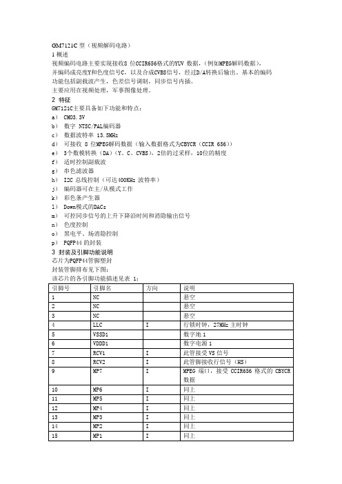
GM7121C型(视频解码电路)1概述视频编码电路主要实现接收8位CCIR656格式的YUV数据,(例如MPEG解码数据),并编码成亮度Y和色度信号C,以及合成CVBS信号,经过D/A转换后输出。
基本的编码功能包括副载波产生,色差信号调制,同步信号内插。
主要应用在视频处理,军事图像处理。
2 特征GM7121C主要具备如下功能和特点:a) CMO3.3Vb)数字 NTSC/PAL编码器c)数据波特率 13.5MHzd)可接收 8位MPEG解码数据(输入数据格式为CBYCR(CCIR 656))e) 3个数模转换(DA)(Y、C、CVBS),2倍的过采样,10位的精度f)适时控制副载波g)串色滤波器h) I2C总线控制(可达400KHz波特率)j)编码器可在主/从模式工作k)彩色条产生器l) Down模式的DACsm)可控同步信号的上升下降沿时间和消隐输出信号n)色度控制o)黑电平、场消隐控制p) PQFP44的封装3 封装及引脚功能说明芯片为PQFP44管脚塑封封装管脚排布见下图:该芯片的各引脚功能描述见表 1:引脚号引脚名方向说明1 NC 悬空2 NC 悬空3 NC 悬空4 LLC I 行锁时钟,27MHz主时钟5 VSSD1 数字地16 VDDD1 数字电源17 RCV1 I 此管接受VS信号8 RCV2 I 此管脚接收行信号(HS)9 MP7 I MPEG端口,接受CCIR656格式的CBYCR数据10 MP6 I 同上11 MP5 I 同上12 MP4 I 同上13 MP3 I 同上14 MP2 I 同上15 MP1 I 同上16 MP0 I 同上17 VDDD2 数字电源218 VSSD2 数字地219 RTCI I 适时控制输入;如果LLC时钟由SAA7111或SAA7151提供,RTCI信号应该链接到对应解码器的RTCO端口,以提高信号质量20 NC 悬空21 SA I I2C总线地址选择输入管脚;、为低电平:从地址为88H为高电平:从地址为8CH22 NC 悬空23 NC 悬空24 C O 色差信号模拟输出25 VDDA1 模拟电源1,供给C路DA电源26 NC 悬空27 Y O 亮度信号模拟输出28 VDDA2 模拟电源2 供给Y路DA电源29 NC 悬空30 CVBS O CVBS符合信号模拟输出31 VDDA3 模拟电源3,供给CVBS路DA电源32 VDDA1 模拟地133 VDDA2 模拟地234 XTAL0 O 晶振输出35 XTAl1 I 晶振输入36 VDDA4 模拟电源4,提供给晶振和参考电压37 XCLK O 晶振时钟输出38 VSSD3 数字地339 VDDD3 数字电源340 RSTN I 复位输入,低有效41 SCl I I2C串行时钟输出42 SDA I/O I2C串行数据端口43 NC44 NC4 功能描述视频编码器对数字亮度和色差信号进行编码,并转换成模拟复合电视信号CVBS和模拟分离电视信号S-video信号输出。
迪伦技术N3 ELVIS III控制板用户指南说明书

User ManualQuanser Controls Board for NI ELVIS IIISetup and Configuration© 2018 Quanser Inc., All Rights ReservedPrinted in Markham, Ontario.This document and the software described in it are provided subject to a license agreement. LabVIEW and National Instruments are trademarks of National Instruments.All other trademarks or product names are the property of their respective owners. Additional Disclaimers: The reader assumes all risk of use of this resource and of all information, theories, and programs contained or described in it. This resource may contain technical inaccuracies, typographical errors, other errors and omissions, and out-of-date information. Neither the author nor the publisher assumes any responsibility or liability for any errors or omissions of any kind, to update any information, or for any infringement of any patent or other intellectual property right.Neither the author nor the publisher makes any warranties of any kind, including without limitation any warranty as to the sufficiency of the resource or of any information, theories, or programs contained or described in it, and any warranty that use of any information, theories, or programs contained or described in the resource will not infringe any patent or other intellectual property right. THIS RESOURCE IS PROVIDED “AS IS.” ALL WARRANTIES, EITHER EXPRESS OR IMPLIED, INCLUDING, BUT NOT LIMITED TO, ANY AND ALL IMPLIEDWARRANTIES OFMERCHANTABILITY, FITNESS FOR A PARTICULAR PURPOSE, AND NON-INFRINGEMENT OF INTELLECTUAL PROPERTY RIGHTS, ARE DISCLAIMED. No right or license is granted by publisher or author under any patent or other intellectual property right, expressly, or by implication or estoppel.IN NO EVENT SHALL THE PUBLISHER OR THE AUTHOR BE LIABLE FOR ANY DIRECT, INDIRECT, SPECIAL, INCIDENTAL, COVER, ECONOMIC, OR CONSEQUENTIAL DAMAGES ARISING OUT OF THIS RESOURCE OR ANY INFORMATION, THEORIES, OR PROGRAMS CONTAINED OR DESCRIBED IN IT, EVEN IF ADVISED OF THE POSSIBILITY OF SUCH DAMAGES, AND EVEN IF CAUSED OR CONTRIBUTED TO BY THE NEGLIGENCE OF THE PUBLISHER, THE AUTHOR, OR OTHERS. Applicable law may not allow the exclusion or limitation of incidental or consequential damages, so the above limitation or exclusion may not apply to you.Safety InformationThe following symbols and definitions are interchangeably used throughout the User Manual:SymbolDescriptionCaution: consult documentation for additional information Attention: Observe precautions for handling electrostatic sensitivedevicesThe Quanser Controls BoardThe Quanser Controls board, pictured in Figure 1 is a complete platform for investigating almost all aspects of modern control theory from system modeling and PID control to stability and digital control design. The system consists of a deterministic DC motor with a high-resolution encoder, as well as a pendulum attachment for balance control. Complete courseware and software is provided for a large compliment of typical control challenges.Figure 1: The Quanser Controls boardMain Features•Direct-drive brushed DC motor•512 count encoder mounted on the motor (giving 2048 count granularity with quadrature decoding), and on the pendulum arm•Built in deterministic PWM amplifier mapped to theoretical motor models•DC motor current senseCautionThis equipment is designed to be used for educational and research purposes and is not intended for use by the general public. The user is responsible to ensure that the equipment will be used by technically qualified personnel only.System Hardware ComponentsThe major components of the application board are identified in Figure 3.Table 1: Application board hardware componentsID Component IDComponent1Inertia Load 4PCI Connector for interfacing with NIELVIS III2 DC motor and encoder 5 Pendulum encoder (optional)3Pendulum encoder connector6Pendulum encoder data cable(optional)Figure 3: Quanser mechatronic systems board components1456DC MotorThe application board includes a direct-drive brushed DC motors to drive either the inertia load or pendulum arm. The motor specifications are given in Table 2.The included motor is a Premotec CL40 Series Coreless DC Motors. The complete specification sheet for the motor is available from Allied Motion.Caution Exposed moving parts.EncoderThe encoders used to measure the angular position of the motor and pendulum are single-ended, optical shaft encoders. They output 2048 counts per revolution in quadrature mode (512 lines per revolution).The included encoders are the US Digital E8P-512-118 single-ended optical shaft encoder. The complete specification sheet of the encoders is available from US Digital. EnvironmentalThe QNET Mechatronic Systems is designed to function under the following environmental conditions:•Standard rating•Indoor use only•Temperature 5◦C to 40◦C•Altitude up to 2000 m•Maximum relative humidity of 80% up to 31◦C decreasing linearly to 50% relative humidity at 40◦C•Pollution Degree 2•Maximum transient overvoltage 2500 V•Marked degree of protection to IEC 60529: Ordinary Equipment (IPX0)System ParametersTable 2: Application board system parametersSymbol Description ValueDC MotorV nom Nominal motor voltage 18.0 V τnom Nominal motor torque 22.0 Nmm ωnom Nominal speed 3050 RPMI nom Nominal current 0.540 AR m Terminal resistance 8.4 Ωk t Torque constant 0.042 Nm/A k m Motor back-emf constant 0.042 V/(rad/s) J m Rotor inertia 4.0 x 10⁻⁶ kgm2 L m Rotor inductance 1.16 mH ϴE Encoder count angle (in quadrature) 0.176 deg m h Module attachment hub mass 0.0106 kg r h Module attachment hub radius 0.0111 m J h Module attachment moment of inertia 0.6 x 10⁻⁶ kg-m2 Inertia Discm d Disc mass 0.053 kg r d Disc radius 0.0248 m Rotary Pendulum Module (Optional)m r Rotary arm mass 0.095 kg L r Rotary arm length 0.085 m m p Pendulum link mass 0.024 kg L p Pendulum link length 0.129 m System SetupThe procedure to set up the Quanser Controls board on the NI ELVIS III module is detailed in this section.Caution If the equipment is used in a manner not specified by themanufacturer, the protection provided by the equipmentmay be impaired.ESDWarningThe electrical components on the Quanser Mechatronic Systems board are sensitive to electrostatic discharge (ESD). Before handling the board ensure that you have been properly grounded.Figure 3: Components of the NI ELVIS IIIID ComponentIDComponent 1Antenna connector 6 Connection data screen 2 Ethernet connector 7 PCI connector 3 USB C connector 8 Handle latching hooks 4 Power cable 9 Status LEDs 5Power switch10 Application board power buttonCautionDo NOT make the following connections while power issupplied to the application board!Follow these instructions to setup the application board on the NI ELVIS III:61 2 34 5109781. Power on the ELVIS III2. Connect the ELVIS III to the network or to your computer via USB C3. Ensure the LED on the application board power button is NOT lit4. Position the handle of the application board over the handle latching hooks5. Position the PCI connector on the application board so that it aligns with the PCIconnector on the ELVIS III6. Push the application board upward until the PCI connector is firmly seated7. Press the application board power button and ensure the LED on the button is lit TroubleshootingPlease review the following before contacting technical support.1. Verify the board is properly seated on the ELVIS III and that it has power.2. Verify that the ELVIS III is correctly set up as outlined in the NI productdocumentation.You are getting 'VI Missing' messagesMake sure the required LabVIEW add-ons listed in the Quick-Start Guide are installed. Verify that the correct LabVIEW version is installed (The ELVIS III is only compatible with LabVIEW 2018 or later).Board does not respondCheck that the source distribution has been deployed as outlined above.。
斑马技术公司DS8108数字扫描仪产品参考指南说明书

Seagate ST320423A、ST315323A、ST310212A 磁盘驱动家庭安装指南说明

U10™ Family Installation GuideST320423A, ST315323A, ST310212AThe Easiest Way to Install Your DriveDiscWizard ™ is Seagate’s exclusive Windows program that is included with your drive for easy drive installation. Y ou can use this software if youalready have a bootable hard drive in your computer and you are running Windows 98 or Windows 95.Run DiscWizard before installing your drive for customized step-by-step instructions for your system.T o run DiscWizard:• Select Run from the Windows Start menu and type x :\setup , where x is the drive letter of your diskette or CD-ROM.If you cannot run DiscWizard, follow the instructions on this installation sheet to install and configure your drive.What You Need• Phillips screwdriver and four 6-32 UNC drive mounting screws• A standard 40-pin A T A interface cable, or an 80-conductor cable to runUltra A T A 66 (max length: 18 inches)• An unused drive power cable for your new driveUltra ATA/66 RequirementsThe drive can support transfer rates up to 66 Mbytes per second(UDMA 4) in Ultra A T A/66 mode. For your drive to run in this mode, you need the following:• A computer that supports UDMA modes 3 and 4• A 40-pin 80-conductor cable (available from your dealer)• A software utility to confirm and activate Ultra A T A/66. Seagate ®providesa utility called UA T A66.exe that is included on your CD, or you can download it from our Web site at .• The Windows 98 operating systemHandling PrecautionsDisc drives are extremely fragile. Do not drop or jar the drive.Keep the drive in the protective SeaShell ™ container until you are ready to install it. This will minimize handling damage.The drive is enclosed in a black, flexible cover called a SeaShield ®.Do not remove this permanent cover—it protects the drive from electrostatic discharge (ESD) and minor impact damage.Protect your drive from static discharge by wearing a grounded wrist strap throughout the installation process.Always handle the drive by the edges or frame.Do not apply pressure or attach labels to the circuit board or the top of the drive.Setting the JumpersRefer to the jumper settings below to configure the drive for your system.Options jumper block (J8)• Master or single-drive: The drive is shipped configured for a masteror a single-drive with a jumper set on pins 7 and 8.• Drive is slave: T o configure the drive as a slave, or second drive onthe cable, remove all the jumpers.• Master with non-ATA compatible slave: Use this setting if the slavedrive is not recognized. Configure the master drive with a jumper set on pins 5 and 6 and pins 7 and 8 to enable this option.• Cable-select option: Computers that use cable-select determine themaster and slave drives by selecting or deselecting pin 28, CSEL, on the interface bus. T o enable cable select, set a jumper on pins 5 and 6.Attaching Cables and Mounting the Drive1. Attach one end of the drive interface cable to the interface connector on your computer’s motherboard (see your computer manual for connector locations).Caution. Align pin 1 on the motherboard connector with pin 1 onyour drive connector. Pin 1 is marked by a stripe on one side of the cable.2. Attach the interface connector and the power connector to the drive.Note. Y ou can mount the drive in any orientation. Usually it is mounted with the circuit board down.3. Secure the drive in the computer using four 6-32 UNC mounting screws in either the side-mounting or bottom-mounting holes. Insert the screws no more than 0.20 inch (5.08 mm) into the bottom-mounting holes and no more than 0.14 inch (3.55 mm) into the side-mounting holes.! Caution. Do not overtighten the screws or use metric screws. Thismay damage the drive.Configuring the BIOSFor your computer to recognize your new drive, configure your computer’s BIOS as follows:1. Run the system setup program.2. Enable LBA mode and UDMA mode, if available.3. Select the auto-detect option. If this is not available, select “User-defined drive type” and enter the CHS (cylinder, head, sectors)parameters for your drive from the table listed below. The CHSaddressing supports capacities up to 8.4 Gbytes only. T o access the full capacity of the drive, use LBA mode.4. Save and exit the system setup program.BIOS SettingsCHS ModeLBA Mode Drive Model Cylinders Heads Sectors Total Sectors*ST320423A 16,383166340,011,300ST315323A 16,383166330,008,475ST310212A16,383166320,005,650*One sector equals 512 bytes.Publication Number: SG35346-001, Rev. ASlaveIf you are using a 40-pin 80-conductorcable, attach the blue connector to the motherboard, the black connector to the master drive, and the grey connector to the slave.Preparing the Drive with Disk ManagerInstalling a Single DriveIf you are installing a single drive, we recommend using Disk Manager to automatically partition and format your drive. This software is stored on the diskette or CD provided with your drive. T o run Disk Manager:1.Boot your computer from your Windows 98 or 95 startup diskette.2. Insert your DiscWizard diskette or CD. If you are using the CD,change to the drive letter of your CD-ROM.3. At the prompt, type dm. Then press ENTER. Disk Manager will guideyou through the installation process.4. Proceed to the section on “Loading the Operating System.”Installing a Slave DriveIf you are installing a second drive, or slave, to your system, use the DiscWizard software provided with your drive.Note. If you do not want to install your drive using Disk Manager, see “Standard DOS installation” below to partition and formatyour drive.Standard DOS InstallationCaution.Partitioning or formatting a drive erases all data on it.Seagate assumes no liability if you erase your data.Drive PartitioningPartitioning divides the drive into sections or partitions that function as separate logical drives (labeled C,D,E, etc.). T o partition your new drive:1. Insert a bootable DOS diskette and restart your computer.2. T ype fdisk and press ENTER. If you have two drives installed,select your new drive from option five of the FDISK menu.3. Select “Create DOS partition or logical DOS drive” by pressing 1.Then press ENTER.4. Select “Create Primary DOS partition” by pressing 1 again. Createyour first drive partition. T o make the partition bootable, mark thepartition as active.5. Verify that all space on your new drive has been partitioned. If neces-sary, create an extended partition with additional logical drives.Drive FormattingCaution. Use the correct drive letters to prevent formatting a drive that already contains data.At the A: prompt, type format x:/s. where x is the letter of your first new partition. Repeat the format process for all new partitions. Proceed to “Loading the Operating System” below.Loading the Operating System1. Boot your computer from your Windows 98 or 95 startup diskette withthe Windows CD loaded.2. At the prompt, type x:\setup, where x is the drive letter of your CD- ROM drive. Continue with the Windows setup instructions.TroubleshootingIf your drive is not working properly, follow these troubleshooting steps.1. Does the drive spin up? A spinning drive produces a faint whineand clicking noise that begins when power is applied. If your drive does not spin, check that the power connector and interface cable are securely attached and the jumpers are installed correctly.2. Does the computer recognize the drive? Verify that the drive isenabled in the system CMOS or setup program. If not, select theautodetect option and enable it. If your drive has a problem, it may not be recognized by the system.3. Does FDISK detect the drive? Run the FDISK program located onyour Windows startup diskette. T ype fdisk/status to verify thatyour hard drive is present.4. Does Scandisk find the drive defect-free? Scandisk is a utilitylocated on your Windows startup diskette that scans the drive for de-fects. If defects are detected, this may be an indication of a problem. 5. Why won’t the drive format to full capacity? Verify that your BIOShas autodetect and LBA mode enabled. Otherwise you may need to use Disk Manager, located on your diskette or CD, to achieve the full capacity of your drive.Note. If the above steps do not solve the problem, contact your dealer or visit to download SeaT ools discdiagnostics software and more troubleshooting advice.Seagate Support ServicesInternetFor online information about Seagate products, visit or e-mailyourdiscquestionsto:***********************.Technical SupportIf you need further help installing your drive, first consult your dealer. Dealers are familiar with their unique system configurations and can help you with system conflicts and other technical issues. If you need additional help, you can talk to a Seagate technical support specialist. Before calling, note your system configuration and drive model number. Africa+31-20-316-7222Poland00 800-311 12 38 Australia+61-2-9725-3366Spain900-98 31 24Austria0 800-20 12 90Sweden0 207 90 073Belgium0 800-74 876Switzerland0 800-83 84 11 Denmark80 88 12 66Singapore+65-488-7584France0 800-90 90 52T aiwan+886-2-2514-2237 Germany************T urkey00 800-31 92 91 4Hong Kong+852 2368 9918United Kingdom************Ireland 1 800-55 21 22USA/Canada/1-800 SEAGA TE orItaly800-790695Latin America+1-405-936-1234Middle East+31-20-316-7222Other EuropeanNetherlands************Countries+ 31-20-316-7222 Norway800-113 91Warranty T o determine the warranty status of your Seagate disc drive, contact your place of purchase or visit our Web site at for more information. RMA (Return Merchandise Authorization) Run SeaT ools to diagnose your drive before requesting a return authorization. In addition, please verify that your drive is defective by following the troubleshooting checklist in this guide. Seagate offers comprehensive customer support for all Seagate drives worldwide. Seagate customer service centers are the only facilities authorized to service Seagate drives. Drive return procedures vary depending on geographical location and are subject to current International T rade Regulations.Shipping Y our DriveCaution. Back up the data on your drive before shipping it. Seagate assumes no responsibility for data lost during shipping or drive repair. Shipping a drive in an unapproved container voids the warranty. Pack the drive with foam rubber only. Do not use peanuts, bubble wrap or newspapers.Keep your original box and packing materials for storing or shipping your drive. T o preserve the warranty status of your drive, any product returned to Seagate must be properly packaged in the original box or a Seagate-approved container to prevent physical and electrical damage while in transit.Electromagnetic Compliance for the European Union This model complies with the European Union requirements of the Electromagnetic Compatibility Directive 89/336/ EEC of 03 May 1989 as amended by Directive 92/31/EEC of 28 April 1992 and Directive 93/68/EEC of 22 July 1993. Compliance of this drive, as a system component, was confirmed with a test system. We cannot guarantee that your system will comply. The drive is not meant for external use (without properly designed enclosure, shielded I/O cable, etc.). Sicherheitsanleitung 1. Das Gerrät ist ein Einbaugerät, das für eine maximale Umgebungstemperatur von 55°C vorgesehen ist.2. Zur Befestigung des Laufwerks werden 4 Schrauben 6-32 UNC-2A benötigt. Bei seitlicher Befestigung darf die maximale Länge der Schrauben im Chassis nicht mehr als 3,3 mm und bei Befestigung an der Unterseite nicht mehr als 5,08 mm betragen.3. Als Versorgungsspannugen werden benötigt: +5V ± 5% 0,6A; +12V ±% 0,8A (1,9A fur ca. 30 Sek. fur ± 10%)4. Die Versorgungsspannung muss SEL V entsprechen.5. Alle Arbeiten auf dem Festplatte dürfen nur von Ausgebildetem Servicepersonal durchgeführt werden. Bitte entfernen Sie nicht die Aufschriftenschilder des Laufwerkes.6. Der Einbau des Laufwerkes muss den Anforderungen gemäss DIN IEC 950 VDE 0805/05.90 entspreche.© 2000 Seagate T echnology, Inc. All rights reserved.Publication Number: SG35346-001, Rev. A, February 2000Seagate, Seagate T echnology, the Seagate logo, U10, DiscWizard, SeaShell and SeaShield are either registered trademarks or trademarks of Seagate T echnology, Inc. All other trademarks are the property of their respective owners.。
- 1、下载文档前请自行甄别文档内容的完整性,平台不提供额外的编辑、内容补充、找答案等附加服务。
- 2、"仅部分预览"的文档,不可在线预览部分如存在完整性等问题,可反馈申请退款(可完整预览的文档不适用该条件!)。
- 3、如文档侵犯您的权益,请联系客服反馈,我们会尽快为您处理(人工客服工作时间:9:00-18:30)。
saa7113芯片的驱动与初始化引言:SAA7113是飞利浦公司视频解码系列芯片的一种,非常具有代表性,在很多视频产品如电视卡、MPEG2、MPEG4中都有应用,熟悉了7113的原理后,对其它系列芯片SAA7114、7115、7118就会很容易理解。
SAA7113的主要作用是把输入的模拟视频信号解码成标准的“VPO”数字信号,相当于一种“A/D”器件。
7113兼容全球各种视频标准,在我国应用时必须根据我国的视频标准来配置内部的寄存器,即初始化,否则7113就不能按要求输出,可以说对7113进行研发的主要工作就是如何初始化。
对7113初始化需要通过I2C总线进行,本文给出用51单片机控制的例子。
1.SAA7113的基本原理与应用SAA7113是一种视频解码芯片,它可以输入4路模拟视频信号,通过内部寄存器的不同配置可以对4路输入进行转换,输入可以为4路CVBS或2路S视频(Y/C)信号,输出8位“VPO”总线,为标准的ITU 656、YUV 4:2:2格式。
7113兼容PAL、NTSC、SECAM多种制式,可以自动检测场频适用的50或60Hz,可以在PAL、NTSC之间自动切换。
7113内部具有一系列寄存器,可以配置为不同的参数,对色度、亮度等的控制都是通过对相应寄存器改写不同的值,寄存器的读写需要通过I2C总线进行。
7113的模拟与数字部分均采用+3.3V供电,数字I/O接口可兼容+5V,正常工作时功耗0.4W, 空闲时为0.07W。
7113需外接24.576MHz晶体,内部具有锁相环(LLC),可输出27MHz的系统时钟。
芯片具有上电自动复位功能,另有外部复位管脚(CE),低电平复位,复位以后输出总线变为三态,待复位信号变高后自动恢复,时钟丢失、电源电压降低都会引起芯片的自动复位。
7113为QFP44封装。
7113的典型应用如下图所示。
2.SAA7113的寄存器简要介绍SAA7113的地址从00H开始,其中14H、18H~1EH、20H~3FH、63H~FFH均为保留地址,没有用到,00H、1FH、60H~62H为只读寄存器,只有以下寄存器可以读写:01H~05H(前端输入通道部分),06H~13H、15H~17H(解码部分),40H~60H(常规分离数据部分)。
下面列表对7113中的寄存器进行简要说明,其中默认值为芯片复位后的寄存器默认值,设置值为可以适用于我国PAL制式的设置参数,这些参数只供参考,详细信息请参考7113数据手册,有些参数如亮度等可以根据用户的需要适当更改。
3.SAA7113寄存器的配置方法SAA7113的寄存器配置通过I2C总线来进行,遵从I2C总线协议,下面从读、写两个方面来说明操作的格式:对7113寄存器的“写”操作:S P对7113寄存器的“读”操作:说明:S:起始位,条件是SCL高电平时SDA有下降沿;Sr:重复设一个起始位Slave address W:7113芯片地址+写标志,0100 1010 = 4AH,若RTS0通过3.3K 电阻接地,则为48H;Slave address R:7113芯片地址+读标志,0100 1011 = 4BH,若RTS0通过3.3K 电阻接地,则为49H;ACK-S:7113产生的回应信号;ACK-m:主机产生的回应信号;Subaddress:寄存器地址;P:停止位,条件是SCL高电平时SDA有上升沿;对多个寄存器操作时,寄存器地址有自动加1功能。
4.用51单片机对7113初始化和控制SAA7113的初始化就是对寄存器配置合适的参数,使其能够有符合要求的输出。
寄存器配置通过I2C总线来进行,很多可以控制I2C总线的器件都可以作为主器件对7113进行初始化,这里介绍用51单片机初始化7113的例子。
51单片机和7113的硬件连接非常简单,只要把单片机的两个I/O口(如P1.0、P1.0)直接和7113的SCL、SDA管脚相连,再加上上拉电阻即可。
用单片机初始化7113的主要任务是程序的编写,首先要熟悉I2C总线协议,根据I2C总线的原理写出启动、停止、应答信号等的子程序,由子程序再写出发送、接收1个字节的程序,然后根据7113的寄存器操作格式写出读写寄存器的程序,最后根据以上的子程序写出初始化7113的程序段。
对7113的控制一般是改变色度、亮度等指标以及输出管脚的输出信号,这可以通过修改相应寄存器的值来完成,程序上写出“读写命令”即可。
下面以程序段的形式给出初始化SAA7113以及读写寄存器的具体例子,以供参考。
SDA BIT P1.0SCL BIT P1.1I2C_ERROR BIT 00H ;I2C总线数据传输出错标志DeviceaddressW EQU 4AH ;7113器件地址+写DeviceaddressR EQU 4BH ;7113器件地址+读Subaddress EQU 4DH ;7113寄存器地址字节在单片机中的存放地址DATA_I2C EQU 50H ;设置写入或读出数据在单片机中的存放地址;*************启动**************I2C_START: SETB SDANOPSETB SCLNOPCLR SDANOPCLR SCLRET;***************停止************** I2C_STOP: CLR SDANOPSETB SCLNOPSETB SDANOPRET;************送应答位************ SEND_ACK: CLR SCLNOPCLR SDANOPSETB SCLNOPNOPCLR SCLNOPSETB SDARET;***********送非应答位*********** SEND_NOACK: SETB SDANOPSETB SCLNOPNOPCLR SCLNOPRET;***********检查应答位************ CHECK_ACK: NOPCLR SCLNOPSETB SDANOPSETB SCLNOPNOPMOV C, SDAMOV I2C_ERROR, CCLR SCLNOPRET;*******发送1字节数据,待送数据在A中******I2C_SEND_1BYTE:MOV R0, #8SEND100: RLC AMOV SDA, CNOPSETB SCLNOPNOPCLR SCLDJNZ R0, SEND100RET;*******接收1字节数据,接收数据放在A中*****I2C_RECEIVE_1BYTE:MOV R0, #8RECV100: SETB SDANOPSETB SCLNOPNOPNOPMOV C, SDACLR SCLRLC ADJNZ R0, RECV100RET;*******通过I2C总线向某一寄存器写入一个字节数据*********I2C_WRITE: ACALL I2C_START ;发启动信号MOV A, # DeviceaddressW ;调7113地址+写ACALL I2C_SEND_1BYTE ;发送7113地址及“写”命令 ACALL CHECK_ACK ;检查7113的应答信号JNB I2C_ERROR, WR200 ;应答正确,继续WR100: ACALL I2C_STOP ;应答不对,返回RETWR200: MOV A, Subaddress ;调寄存器地址ACALL I2C_SEND_1BYTE ;发送寄存器地址ACALL CHECK_ACK ;检查7113的应答信号JB I2C_ERROR, WR100 ;应答不对,返回MOV A, DATA_I2C ;调准备写入的数据ACALL I2C_SEND_1BYTE ;发送数据字节ACALL CHECK_ACKJB I2C_ERROR, WR100ACALL I2C_STOP ;发停止信号RET;*******通过I2C总线读出某一寄存器的数据*********I2C_READ: ACALL I2C_STARTMOV A, # DeviceaddressW ;调7113地址,写入ACALL I2C_SEND_1BYTEACALL CHECK_ACKJNB I2C_ERROR, RD200RD100: ACALL I2C_STOPRETRD200: MOV A, Subaddress ;调要读的寄存器地址ACALL I2C_SEND_1BYTE ; 发送寄存器地址字节ACALL CHECK_ACKJB I2C_ERROR, RD100ACALL I2C_START ;重发起动信号MOV A, # DeviceaddressR ;调7113地址,读ACALL I2C_SEND_1BYTEACALL CHECK_ACKJB I2C_ERROR, RD100ACALL I2C_RECEIVE_1BYTE ;接收读出的数据MOV DATA_I2C, A ;读出数据转存ACALL SEND_NOACK ;发送非应答位ACALL I2C_STOP ;停止RET;***************初始化7113,配置各寄存器************************ INIT_SAA7113: MOV DPTR, #SAA7113_SubaddressMOV R7, #28INIT100: MOV A, #0MOVC A, @A+DPTRMOV Subaddress, A ;调寄存器地址MOV A,#28MOVC A, @A+DPTRMOV DATA_I2C, A ;调寄存器配置数据INC DPTRACALL I2C_WRITE ;配置1个寄存器JB I2C_ERROR, INIT200DJNZ R7,INIT100INIT200: RET;***************SAA7113寄存器初始化配置数据********************** SAA7113_Subaddress:DB 01H,02H,03H,04H,05H,06H,07H,08H,09H,0AH,0BH,0CH,0DH,0EHDB 0FH,10H,11H,12H,13H,15H,16H,17H,40H,58H,59H,5AH,5BH,5EH;共28个I2C_REG_VALUE_AI11:DB 08H,0C0H,33H,00H,00H,0EBH,0E0H,0B8H,01H,7EH,46H,43H,01H,01HDB 0FH,00H,0CH,0A7H,00H,00H,00H,00H,02H,00H,54H,07H,80H,00H;*************对SAA7113某一寄存器的改写与读出******************* WRITE_READ: MOV Subaddress, #0AH ; 设寄存器地址为0AHMOV DATA_I2C, #88H ;改寄存器的值为88HACALL I2C_WRITE ;改写ACALL I2C_READ ;读出结语SAA7113在很多产品中都可以应用,但其初始化与控制的原理都一样,本文中的程序段经过实际应用可以保证7113正常工作,其寄存器设置参数与控制方法可以被借鉴或直接应用。