M-AUDIO FireWire410中文说明书
M-AUDIO FIREWIRE SOLO Quick Start 说明书
Introduction (3)Minimum System Requirements (4)Windows (4)MacOS (4)Front Panel Controls and Connectors (4)Rear Panel Connectors (5)Hardware Installation (5)Software Control Panel (6)Mixer Page (6)Hardware Page (7)Sample Rate Detected (7)ASIO/WDM Buffer Size (7)Sync Source (7)S/PDIF Output Source (7)Contact Us (7)Thank you for choosing the M-Audio FireWire Solo. The FireWire Solo has been designed to give you a professional, portable audio interface for your laptop or desktop computer. Using the convenience and dependability of the IEEE 1394 (FireWire™) bus, the FireWire Solo provides your computer with a high-performance, high-resolution audio interface, complete with microphone, instrument and line-level inputs, in a rugged, lightweight, and highly portable design.This Quick Start Guide is meant to get you up and running as quickly as possible. Please consult the User’s manual for more detailed information.IMPORTANT:The FireWire Solo comes with a high-quality six-pin tosix-pin FireWire cable. We strongly suggest you use thiscable, or one of equal quality, to ensure optimum audioperformance. If your computer is equipped with only a four-pin interface, you will need to use the included four-pin tosix-pin FireWire cable. Note that the FireWire Solo requiresa six-pin FireWire connection in order to supply bus power;if you have a four-pin connection you will need to use thesupplied power adapter.NOTE:Some computer manufacturers may use a differentnomenclature to refer to their FireWire connections, such asSony’s “iLink”, or simply “1394.” When in doubt, consult yourcomputer’s owner’s manual.IMPORTANT - IEEE 1394 “FireWire” Users :Reports have come to our attention of isolated problems when hot-plugging IEEE 1394 (aka “FireWire”) devices. Hot-plugging refers to making connections to1394/FireWire ports while one or more of the devices (including the computer) are still powered on. There have been rare occurrences when, after hot-plugging, either the FireWire peripheral or the host computer’s FireWire port are rendered permanently inoperable. While M-Audio products adhere rigidly to the FireWire industry standard and pass stringent internal testing, the possibility remains that hot-plugging your M-Audio FireWire interface to some computers may result in the this type of problem.We strongly encourage you to protect your equipment by refraining from hot-pluggingany bus-powered FireWire device, including the M-Audio family of FireWire products. Connect your FireWire device while both the computer and FireWire device are powered off. Always connect the FireWire device first, and then turn the computer on last. If you are using bus power (on systems with IEEE 1394 6-pin connectors), make sure you first connect the 6-pin cable securely to the FireWire device and to your computer’s FireWire port, and only turn the computer system on after the connections are made.M-Audio is being proactive in investigating any issues that may adversely affect our customers. Please consult the Knowledge Base in the Support section at for updates on this important issue.Be sure that your computer meets these minimum requirements before installing your FireWire SOLO.Windows< Pentium III – 500 MHz or higher< 128 MB RAM< Windows XP (SP2) with DirectX 9.0b or higher< Onboard FireWire connection or installed PCI cardThe FireWire Solo is not supported under Windows 98, Windows ME or Windows 2000. MacOS< Macintosh G3/G4* 500 MHz or higher< OS X 10.2.8 or later, 256 MB RAM or< OX X 10.3.5 or later, 512 MB RAM< Onboard FireWire connection or installed PCI card*G3/G4 accelerator cards not supportedOS X 10.3.5 or later required for Dolby Digital and DTS pass-through with Apple DVD player.1. M icrophone Input - Mic-level input on balanced XLR connector. This connector is only active when theFront/Rear Input Selector (5) is set to “Front” (OUT position). Input from this connector appears in your DAW software as a mono signal on the left side of the stereo input pair.2. C lip indicator - This LED illuminates when the Microphone Input signal level exceeds –1 dBFS. If the ClipIndicator glows steadily, reduce the Microphone Input gain level (4).3. P hantom Power Indicator - This indicator illuminates when the Phantom Power Switch (9) is pressed,indicating that +48VDC is being applied to the Mic Input (1).4. M icrophone Input Gain - This knob controls the amount of gain at the Microphone Input (1), over arange of 0dB to +40dB or greater.5. F ront/Rear Input Selector - This switch selects which pair of analog inputs will be active. When theswitch is in the OUT position, the front panel Microphone Input (1) and Guitar Input (6) are active. When the switch is in the IN position, the rear panel Line Inputs (19) are active.6. G uitar Input - Instrument-level input on unbalanced 1/4” phone connector, for use with guitars, bassesor other instrument-level sources. This connector is only active when the Front/Rear Input Selector (5) is set to “Front” (OUT position). Input from this connector appears in your DAW software as a mono signal on the right side of the stereo input pair.7. C lip indicator - This LED illuminates when the Guitar Input signal level exceeds –1 dBFS. If the ClipIndicator glows steadily, reduce the Guitar Input gain level (8).8. G uitar Input Gain - This knob controls the amount of gain at the Guitar Input (6), over a range of 0dBto +30dB or greater.9. P hantom Power Switch - This switch activates the +48V phantom power, for use with condenser micsrequiring external power. When Phantom Power is active, the Phantom Power Indicator LED (3) is lit.N OTE: It is safe to connect most modern dynamic microphones or line level devices to the channel inputs when phantom power is activated. However, be aware that some older ribbon microphones may be damaged by phantom power, and certain unbalanced line level devices may malfunction or produce an audible hum when phantom power is active. Consult the owner’s manual for these devices before you connect them to phantom power sources.10. O utput Level Control - This knob controls the amount of output gain to the rear-panel Line Output (18)and the front-panel Headphone Output (11).11. H eadphone Output - Stereo 1/4” TRS phone jack output for connection of headphones for monitoringthe output signal. The volume level is controlled by the Output Level Control (10).12. P ower Indicator - This LED illuminates when the FireWire Solo is powered on, either via buss power orthe AC adaptor.13. A C Input - Connect the supplied AC adaptor to this input. The AC adaptor is required when operatingthe FireWire Solo with only a 6-pin to 4-pin FireWire connection, or when using the FireWire Solo asa stand-alone A/D converter. The AC adaptor is not needed when running the FireWire Solo on astandard 6-pin to 6-pin FireWire connection.14. L ock Port - This port is provided for use with a standard Kensington-type computer cable anti-theftdevice.15. F ireWire Ports - Two FireWire (IEEE 1392) connectors. Use one to connect to your computer’s FireWireport. The second may be used as a throughput, to chain additional devices on the FireWire bus.16. S/PDIF Output - S/PDIF digital output on coaxial RCA connector.17. S/PDIF Input - S/PDIF digital input on coaxial RCA connector.18. L ine Outputs - Balanced/unbalanced analog line outputs on 1/4” TRS phone connectors. The signallevel to these outputs is controlled by the front-panel Output Level Control (10).19. L ine Inputs - Unbalanced analog line inputs on 1/4” phone connectors. These connectors are onlyactive when the front-panel Front/Rear Input Selector (5) is set to “Rear” (IN position). Input from these connectors appears in your DAW software as a stereo input pair.NOTE:Do NOT connect the FireWire Solo to your computer until you have run the installer program and completed the installation.Once you have run the installer, power down your computer. Then connect the FireWire Solo to your host computer’s FireWire port using the included cables.If you are using bus power (on systems with IEEE 1394 6-pin connectors), make sure you first connect the 6-pin cable securely to the FireWire device and to your computer’s FireWire port, and only turn the computer system on after the connections are made.The FireWire Solo control panel is installed in your system when you complete the driver installation procedure. To open the control panel:In Windows – A tiny “knob icon” will by placed in the system tray, generally located at the bottom of your Windows desktop. Double-click this icon to open the control panel.On the Mac – The FireWire Solo control panel can be found in the system preferences.Mixer PageThe Mixer page provides output routing and control of the FireWire Solo’s analog and digital inputs, as well as the four virtual channels returning from your Digital Audio Workstation software. It also provides input and output level meters, level controls, stereo linking, solo and mute functions.The Hardware page gives you access to important information and functions of the FireWire Solo.Sample Rate DetectedThis field displays the currently-detected sample rate from the currently selected incoming sync source.ASIO/WDM Buffer SizeIn this field you can select the buffer size you wish to work with. Smaller buffer sizes result in lower latency (latency refers to the time it takes for your input signal to pass through your audio software and appear at the outputs), but may not function well with slower systems.Sync SourceThis field allows you to choose between the FireWire Solo’s INTERNAL clock and an EXTERNAL S/PDIF clock source.S/PDIF Output SourceSelecting “mixer” routes the signals assigned to the S/PDIF output from the control panel mixer to the S/PDIF output. Selecting “Pass Thru” allows a surround-encoded stream such as AC3 or DTS to be sent to the S/PDIF output.For additional help, technical support is available on our website at , where you can fill out our technical support form.Alternatively, you can email us at *******************, or contact us by phone at: (626) 633-9055 Technical support is available by telephone from 7am - 7pm PST.FWSOLO_QS_EN1。
M-AUDIO 410中文说明书

M-AUDIO FireWire410中文说明书1.FireWire410 简介FireWire410 是一个4 进10 出音频接口,它通过IEEE-1394 端口(俗称"火线")与计算机进行连接。
如果你的计算机没有火线端口,只需向计算机经销商购买一块PCI 的火线卡,便能与FireWire410 连接。
笔记本电脑通常都自备火线端口。
FireWire410 包装内带一条高质量的六针到六针1394 数据线,建议你使用它或相同品质的火线与电脑连接。
如果电脑上只有四针火线接口,则需购买一条六针到四针的1394 数据线。
另外需指出,FireWire410 使用六针的端口自供电,若使用四针的火线口,需要为FireWire410 提供外部电源。
提示:火线口即是1394 口,在Sony 设备中又称iLink 口。
FireWire410 提供两个卡侬和大三芯的复合模拟输入口,可以连接话筒,也可接电吉它、电贝司等乐器;八个大三芯模拟输出口及一对S/PDIF 的同轴、光纤输入/输出。
FireWire410 提供了高品质模拟、数字输入输出,支持24 比特的采样精度、96kHz 录音采样频率和192kHz 输出采样频率,S/PDIF 端口支持AC3 和DTS 双编码。
FileWire410 还提供了一进一出MIDI 端口,并有开关选择MIDI 输出或是旁通,可作为独立MIDI 接口使用。
FireWire410 具有简捷实用的软件控制系统,提供了跳线和调音台控制功能,为音频软件虚拟了10 个输出通道。
你可任意分配输入端口到输出端,每个内部通道又支持具有超大控制幅度的辅助发送。
FireWire 还提供了零延迟硬件直接监听和基于ASIO 的超低延迟软监听;具有两个独立的耳机监听输出,信号来源可选择,并有独立增益控制;两个麦克风/乐器功放提供了电平控制和监测功能、48V 幻像电源、20dB 衰减和最大66dB 的增益。
M-Audio NRV10 火焰线FireWire 10入 10出混音器与数字音频接口说明书

4 vFrançais1 Merci d’avoir choisi le mélangeur FireWire NRV10 de M-Audio. La NRV10 combine un mélangeur analogique dehaute qualité avec une interface audio numérique FireWire 10 entrées/10 sorties, vous permettant d’enregistrer jusqu’à dix canaux d’audio directement dans votre dispositif audionumérique assisté par ordinateur et de lesramener vers les canaux du mélangeur analogique. Ses pilotes FireWire à faible latence sont compatibles avec desfréquences d’échantillonnage élevées de 96 kHz en résolution 24 bits et son encombrement réduit le rend idéalpour des utilisations en concert comme en studio.Ce guide de démarrage rapide a été conçu pour vous donner un aperçu de l’utilisation du NRV10, l’objectifétant que vous puissiez commencer sans délai à vous en servir. Même si vous êtes loin d’être novice en matièred’enregistrement numérique et d’informatique, nous vous recommandons de consacrer du temps à la lecture du Manuel de l’utilisateur figurant sur le CD inclus. Vous pourrez ainsi vous familiariser avec les fonctionnalités les plus avancées de votre NRV10 et apprendre comment en tirer le meilleur parti.1 | Installation de la NRV10REMARQUE : NE CONNECTEZ PAS la NRV10 à votre ordinateur tant que vous n’avez pas exécuté leprogramme d’installation.Instructions d’installation pour Windows XPAssurez-vous que la NRV10 n’est pas connectée à l’ordinateur avant de commencer l’installation.21. N ous vous recommandons de télécharger la version la plus récente des pilotes NRV10 sur la pageAssistance > Pilotes sur notre site internet à www.m-audio.fr. C’est le moyen le plus sûr de vous garantir quevous avez les pilotes les plus récents. Si vous installez les pilotes depuis www.m-audio.fr, double-cliquezsimplement sur le fichier une fois son téléchargement terminé.S i vous ne disposez pas d’un accès à internet, vous pouvez installer les pilotes fournis avec la NRV10votre produit dans le menu et cliquez sur “installer”.2. S uivez les instructions données à l’écran par leprogramme d’installation du pilote.3. A différents stades de l’installation, desmessages peuvent vous indiquer que le piloten’a pas passé le test du logo Windows. Cliquezdans ce cas sur Continuer afin de poursuivrel’installation.4. U ne fois l’installation terminée, cliquez sur“Terminer”.5. Eteignez l’ordinateur.6. B ranchez la NRV10 sur une prise électriqueet sur un port FireWire disponible sur votreordinateur.7. A llumez la NRV10, puis démarrez votreordinateur.3F r a n ça i s8. W indows identifie la nouvelle interface et vous demande sivous souhaitez chercher un pilote sur Internet. Sélectionnez9. W indows va maintenant ouvrir l’”Assistant nouveau matérieldétecté”.10. S électionnez l’option “Installer le logiciel automatiquement”,11. Une fois l’assistant terminé, cliquez sur “Terminer”.12. D ès que l’assistant est terminé, vous verrez apparaîtreune fenêtre vous précisant que votre nouveau matériel est installé et prêt à être utilisé.Votre NRV10 apparaît désormais dans Windows sous Panneau de configuration > Sons et multimédia. Vous pouvez accéder au panneau de configuration de la NRV10 en cliquant sur l’icône rouge dans la Barre des tâches.IMPORTANT : Bien qu’il soit théoriquement possible de brancher un périphérique FireWire à chaud, il est fortement conseilléd’éteindre votre ordinateur avant de brancher ou débrancher votre NRV10. Pour plus d’informations sur cette question, consultez la base de connaissances sur http://www.m-audio.fr.4Instructions d’installationpour Mac OS XAssurez-vous que la NRV10 n’est pas connectée àl’ordinateur avant de commencer l’installation.1. N ous vous recommandons de télécharger laversion la plus récente des pilotes NRV10 sur lapage Assistance > Pilotes sur notre site internetà www.m-audio.fr. C’est le moyen le plus sûr devous garantir que vous avez les pilotes les plusrécents. Si vous installez les pilotes depuis www.m-audio.fr, double-cliquez simplement sur lefichier une fois son téléchargement terminé.S i vous ne disposez pas d’un accès à internet,vous pouvez installer les pilotes fournis avec laNRV10 en insérant le CD-ROM FireWire Seriesdans le lecteur CD de votre ordinateur. Votreordinateur affiche automatiquement l’icônedu CD-ROM sur le bureau. Double-cliquezsur cet icône pour visualiser le contenu dudisque. Puis, double-cliquez sur “Ouvrez-moi”.Enfin, sélectionnez votre produit dans le menudéroulant sur l’écran d’accueil puis cliquez sur“Installer”.2. S uivez les instructions à l’écran données par leprogramme d’installation du pilote.3. U ne fois le programme d’installation terminé,cliquez sur “Fermer”.4. Eteignez l’ordinateur.5. B ranchez la NRV10 sur une prise électriqueet sur un port FireWire disponible sur votreordinateur.6. A llumez la NRV10, puis démarrez votreordinateur.Votre NRV10 apparaît dans Mac OS X sous Préférences Système > Son, dans les onglets Entrée et Sortie. Le panneau de configuration de la NRV10 apparaît dansPréférences Système > Autre.IMPORTANT : Bien qu’il soit théoriquement possible de brancher un périphérique FireWire à chaud, il est fortement conseillé d’éteindre votre ordinateur avantde brancher ou débrancher votre NRV10. Pour plus d’informations sur cette question, consultez la base de connaissances sur http://www.m-audio.fr.5 2 | Branchement de la NRV10Votre NRV10 est équipée de cinq entrées micro XLR et huit entrées ligne 6,35 mm. Branchez toutes les combinaisons possibles et imaginables de sources ligne et micro sur ces entrées, tout en vous assurant dechoisir la source d’entrée appropriée sur les sélecteurs ligne/micro de chaque canal. Si vous utilisez un micro à condensateur, n’oubliez pas d’activer le bouton Phantom Power.Vous pouvez brancher des processeurs de signal externe (généralement des processeurs dynamiques) surn’importe lequel des inserts de canal sur les canaux d’entrée 1 à 4, ainsi que sur le Main Mix sur l’arrière. Vouspouvez aussi brancher des processeurs de signal externe (généralement des reverbs ou d’autres dispositifs multi-effets) sur les prises Aux Send et Aux Return de la NRV10.Branchez vos moniteurs ou ampli sur les sorties Main Mix à l’arrière. Les sorties Main Mix sont fournies au formatsXLR et Jacks TRS 6,35 mm. Bien que les deux jeux de prises transmettent le même signal, il est recommandé dansla grande majorité des cas de ne brancher qu’un seul jeu de sorties à la fois. (Si vous branchez les deux jeux de sorties, vous n’endommagerez pas votre mélangeur mais vous risquez une perte de niveaux en sortie). Vous pouvez brancher un jeu supplémentaire d’enceintes ou d’ampli sur les sorties arrière Control Room.Et finalement, branchez le câble FireWire inclus de l’un des ports FireWire sur l’arrière vers l’entrée FireWire devotre ordinateur.IMPORTANT : Un mauvais branchement entre la NRV10 et votre dispositif audionumérique informatisé - en particulier, si vous pressez le bouton d’égalisation pre/post dans certaines configurations - peut provoquer une boucle de feedback et endommager vos oreilles et votre équipement. Veuillez-vous reporter à la Section 10du guide inclus “Contrôler votre audio en direct tout en enregistrant sur votre dispositif audionumérique” avantd’utiliser votre NRV10.63 | Utilisation du Panneau de configurationLe Panneau de configuration vous fournit la possibilité de contrôler certaines des fonctions de base de la NRV10.Reportez-vous au manuel de l’utilisateur pour plus d’informations sur l’utilisation du Panneau de configuration.4 | Informations complémentaires et assistanceLe site web de M-Audio (www.m-audio.fr) contient les derniers pilotes et applications ainsi que des liens utiles vers des articles, des questions fréquemment posées et une assistance technique. Nous vous recommandons de consulter ce site régulièrement pour vous assurer que vous disposez des pilotes les plus récents et des informations les plus à jour pour vos produits M-Audio.© 2006 Avid Technology, Inc. Tous droits réservés. Les caractéristiques du produit, les spécifications, laconfiguration système minimale et la disponibilité peuvent être modifiées sans avertissement. Avid, M-Audio et NRV10 sont soit des marques commerciales soit des marques déposées de Avid Technology, Inc. Toutes les autres marques contenues dans ce document sont la propriété de leurs propriétaires respectifs.e-mail:*****************e-mail:*****************.uke-mail:***************e-mail:********************************e-mail:******************e-mail:***************email:********************** e-mail:**********************。
SM410 8通道模拟量输入模块使用说明书

SM410
HOLLiAS-SM
SM410 采用模块化设计,整体为欧式插件结构,机笼安装卡销固定,支持热插拔。模块与机笼槽 位依据配套防混销识别定位,有效防止错位对硬件造成损伤。SM410 模块外观结构如图 1 所示。
使用说明
状态指示灯
模块上电后,其面板上的状态指示灯(RUN 灯和 COM 灯)显示当前的工作和通讯状态。具体组
7
SM410
HOLLiAS-SM
振铃波抗扰度
电源口:±2.2KV CM, ±1.1KV DM; 信号口:±1.1KV CM, ±0.55KV DM
工频磁场
持续干扰:33/m;瞬间干扰:330A/m
*注:从 SM410-B04 版本开始具有断线、短路、超上限报警、超下限报警四种通道诊断功能。
8
A1 B1
A2 B2
B3
A3
B4
A4
B5
A5
B6
A6
B7
A7
B8
A8
A9 B9
SM3310
Vin+
V Vin-
0~5V
CH+ CH-
A/D
微控
转
换
制器
SM410
SM3310
图 3 电路接口示意图
配置 SM3414 端子模块
现场电流信号电缆直接连接到 SM3414 端子模块的端子排,每路电流信号采用两根导线(屏蔽电缆)
技术指标
SM410 8 通道模拟量冗余输入模块技术指标
输入通道
通道数目
8
量程代号
0x00
信号输入范围 输入量程
0~5V
数据格式
0x0000~0xFFFF
仪表代号 仪表类型选择
GWF410资料

GAMEWELL-FCI12 Clintonville Road, Northford, CT 06472-1610 USA • Tel: (203) 484-7161 • Fax: (203) 484-7118Specifications are for information only, are not intended for installation purposes, and are subject to change without notice. No responsibility is assumed by Gamewell-FCI for their use.©2007 by Honeywell International Inc. All rights reserved. 9021-60294 Rev. A page 1 of 2Flex Series GWF41010 Zone Expandable ConventionalFire Alarm Control PanelDescriptioni 3™ is a trademark of Honeywell International Inc.UL ® is a registered trademark of Underwriter’s Laboratories, Inc.Windows ® is a registered trademark of Microsoft Corporation.The Flex 410 is a ten zone fire alarm control panel (FACP)expandable to twenty or thirty zones using optional CZM-400 zone expander module(s). The Flex 410 is ideal for a wide range of different sized installations such as hotels,schools, correctional institutions, health care facilities,small office buildings, and manufacturing plants. Initiating device circuits (IDCs) for the Flex 410 can be pro-grammed as either ten Class B (Style B) or five Class A (Style D) circuits. This is expandable to either twenty Class B (ten Class A), or thirty Class B (fifteen Class A) IDC cir-cuits. The panel is compatible with a variety of conven-tional two-wire smoke detectors, four-wire smoke detectors, and notification appliances. This includes Sys-tem Sensor i 3™ Series microprocessor-based detectors with advanced features like drift compensation, mainte-nance alert and freeze warning. (See Appendix A of the Flex 410 Installation & Operations Manual PN 151321 for a list of compatible devices.)Outputs include four Class B (Style Y) or two Class A (Style Z) supervised notification appliance circuits (NACs)to annunciate alarm conditions. NAC circuits support single circuit synchronization, regulated. Three programmable auxiliary relay outputs can be programmed to activate (for all zones or individual zones): pre-alarm, fire alarm, auxil-iary alarm, alarm by zone and system or circuit troubles (e.g., loss of AC, low battery, communication failure, phone line trouble, fire drills, and NAC trouble).The Flex 410 includes a built-in digital alarm communicator (DACT) to report status to a central station. A user-friendly,two-line LCD display and tactile keypad makes system pro-gramming and control easy. The Flex 410 cabinet can be flush- or surface-mounted and a Plexiglas window/dead-front door kit is available where jurisdictions require. The fully regulated, efficient 6-amp power supply with charger ensures adequate power is available at all times.The Flex 410 fire alarm control panel is listed to UL ® Standard 864, 9th Edition.Features•10 Class B (Style B) or 5 Class A (Style D) initiating device circuits (IDCs), expandable up to 30 Class B or 15 Class A IDCs with optional zone expander(s)•Supervised zone expanders and I/O modules can be mounted remotely in optional accessory cabinet •All zones compatible with 2- and 4-wire detectors•Built-in digital alarm communication transmitter (DACT) with dual phone line monitors• 4 Class B (Style Y) or 2 Class A (Style Z) supervised notification appliance circuits (NACs)•Selectable/programmable NAC output patterns:- ADA compliant strobe synchronization- ANSI audible signals as required by NFPA 72- Single Stroke BI - Constant output - California code - March code(continued next page)GWF4107165-1288:182SIGNALINGS521An ISO 9000-2000 CompanyGAMEWELL-FCI12 Clintonville Road, Northford, CT 06472-1610 USA • Tel: (203) 484-7161 • Fax: (203) 484-71189021-60294 Rev. A page 2 of Features (continued)•Built-in 2-line, 32-character LCD display with easy-to-read English language readouts• 3 programmable general purpose relays •Built-in walk test•Programmable from keypad, remote annunciator, or using direct connect port for on-site downloading with SmartProgram 400 software (Windows ®-based)•Programmable features to minimize false alarms: smoke verification, pre-alarm delay, cross-zoning, and enhanced verification•Municipal box service and polarity reversal signaling •Programmable date settings for Daylight Savings Time, and clock source setting options for 50 Hz, 60 Hz or internal clockOptionsGWCZM-400Each GWCZM-400 zone expander pro-vides the control panel with ten additional Class B (Style B) zones or five Class A (Style D) zones. The GWCZM-400 con-nects to the control panel via the panel SBUS and is supervised and power limited.Up to two zone expanders can be used per panel. Mounts in FACP or into a GWCAB400-A accessory cabinet.GWIOM-410This status display module provides out-puts and control functions for remote annunciation of alarm, trouble, and supervi-sories for each zone. The system can supervise up to eight GWIOM-410 status display modules. Mounts in FACP or into a GWCAB400-A accessory cabinet.GWRAN-400 The GWRAN-400 remote annunciator canperform all system control operations. It also provides trouble and alarm information and can be used for programming. The FACP can support up to four GWRAN-400remote annunciators. Mounts in dual gang electrical box.GWCAB400-A This accessory cabinet is used for mount-ing GWCZM-400 zone expander and/or GWIOM-410 status display module.GWPLEX-2GA This door option combines a dead-frontpanel with a clear bicarbonate window to limit access to the control panel. Used for jurisdictions where single button operation is required.SpecificationsAC Power 120 VAC, 60Hz, 3 ABatteryMax. charging circuit: 27.4 VDC@ 0.75AMax. charger capacity: 33 Ah(two 18Ah batteries fit inside FACP)Operating Power 24 VDC operating voltage Total DC Load6 AInitiating Device Circuits (IDC)(2-wire smoke): 17.5- 27.4 VDCAlarm current draw (panel): 460 mA Short circuit current: 95 mA maximum Standby current draw (panel): 140 mA Maximum impedance: 50 ohms Accessory Power 27.4 VDC, 1 ANotification Circuits (NAC)27.4 VDC, 3 A max/output (6 A total)Maximum line impedance: 1.5 ohm Programmable 2.5 A, 24 VDC (inductive), 5 A, 24 VDC Relays (resistive), non-power limited Operating Range32° F to 120° F (0° C to 49° C)Flex 410 Cabinet 26 3/8" x 17 3/16" x 4" (67 x 44 x 10 cm)(H x W x D)Accessory Cabinet10 3/8" x 10 3/16" x 3" (26 x 26 x 8 cm)Ordering InformationPart NumberDescriptionGWF410Flex 410 FACP , 10 zones, expandable to 20 and 30 zones, 120 VAC GW151321Flex 410 Installation & Operation ManualOptions:GWCZM-400Zone expander module; adds 10 Class B or 5 Class A circuitsGWIOM-410Input / output relay, supervisory status moduleGWRAN-400Remote annunciator for Flex 410 GWCAB400-A Accessory cabinet for mounting GWCZM-400 or GWIOM-410GWPLEX-2GA Dead-front door with Plexiglas window SP400SmartProgram 400 for remoteprogramming of the Flex 410 using a PC (available only to authorized distributors at ESD extranet)。
西门子MM420变频器简明操作手册
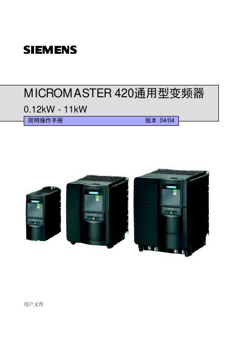
0.12kW - 11kW
简明操作手册
版本 04/04
用户文件
警告, 注意和说明
以下的“警告”,“注意”和“说明”是为了您的安全而提出的,是防止设备或与其连接的机械部 件受到损伤而采取的一项措施。在处理 MICROMASTER420 变频器的相关事项时,通常都要涉及 本节中列出的“警告”,“注意”和“说明”,它们分为以下几类:常规的,有关运输和存放,调 试,操作,维修以及拆卸和废品处理。
6.2.9 固定频率 (FF).....................................................................................................6-8
6.2.10 JOG (点动)..........................................................................................................6-8
2
电气安装 .............................................................................................................................................2-1
即使变频器处于不工作状态,其电源输入端子,直流回路和电动机接线端子仍然可能带 有危险电压,因此,在电源关断 5 分钟,等待电容器放电完毕以后才允许在本设备上开 展任何安装工作。
说明 在安装和调试变频器之前,请您务必仔细阅读这些安全规则和警告,以及设备上粘贴的所 有警示标志。 确保警示标志置于醒目的地方,并更换已脱落或损坏的标志。
爆米花A410(A400)中文说明书

爆米花 A-400 播放机用户手册
目录 1. 产品介绍................................................................................................3 2. 包装内容 ............................................................................................ 3 3. 安全细则 ............................................................................................. 4 4. 技术参数 ............................................................................................. 5 5. 操作流程 ..............................................................................................6 5.1 爆米花 A-400 整体外观 .................................................................. 6 5.2 通过HDMI连接电视 ...................................................................... 7 5.3 连接电视的复合视频...................................................................... 8 5.4 连接电视的色差分量视频 ............................................................. 9 6. 遥控器 ................................................................................................ 10 7. 主界面介绍 ....................................................................................... 16 8. 快速安装向导 ................................................................................... 17 9. 设置 ..................................................................................................... 23 9.1 基本设置 .......................................................................................... 24 9.2 音频 .................................................................................................. 25 9.3 视频 ................................................................................................... 26 9.4 网络设置 .......................................................................................... 29 9.5 网络共享 ......................................................................................... 30 9.5.1 添加共享 ...................................................................................... 31 9.5.2 浏览共享 ...................................................................................... 32 9.5.3 编辑共享 ...................................................................................... 33 9.6 家长指引级别 ................................................................................ 34 9.7 BD/DVD/CD 设置 ......................................................................... 35 9.8 固件更新 .......................................................................................... 36 9.8.1 固件更新 ...................................................................................... 37 10. 软件市场.......................................................................................... 38 10.1 登录................................................................................................. 40 11. 文件浏览 ......................................................................................... 41 11.1 设置 .......................................................................................... 41
Shure MX405和MX410微型曲线麦克风说明书

MX410 and MX405Miniature GoosenecksMX400SMPSurface Mount PreampMX400DPWired Desktop Base (also available as MX890 Wireless Desktop Base)Specifications (subject to change)TypeCondenser (electret bias)Frequency Response 50–17000 HzPolar Pattern (at 1 kHz)MX405/C, MX410/C: CardioidMX405/S, MX410/S: Supercardioid Output Impedance EIA Rated at 150 Ω (170 Ω actual)Output ConfigurationActive BalancedSensitivity (at 1 kHz , open circuit voltage)Cardioid: –35 dBV/Pa (18 mV)Supercardioid: –34 dBV/Pa (21 mV)1 Pascal=94 dB SPL Maximum SPL (1 kHz at 1% THD, 1 kW load)Cardioid: 121 dBSupercardioid: 120 dB Equivalent Output Noise (A-weighted)Cardioid: 28 dB SPLSupercardioid: 27 dB SPL Signal-to-Noise Ratio(referenced at 94 dB SPL at 1 kHz)Cardioid: 66 dBSupercardioid: 68 dB Dynamic Range (1 kΩ load at 1 kHz)93 dBCommon Mode Rejection (10 Hz to 100 kHz)45 dB minimum Preamplifier Output Clipping Level (1% THD)-8 dBV (0.4 V)Polarity3-Pin XLR: Positive sound pressure on diaphragm produces positive voltage on pin 2 relative to pin 3 of output XLR connector.5-Pin XLR: Positive sound pressure on diaphragm produces positive voltage on pin 4 relative to pin 2 of output XLR connector.WeightMX405: 0.054 kg (0.119 lbs)MX410: 0.068 kg (0.150 lbs)MX400DP: 0.516 kg (1.138 lbs)MX400SMP (w/ Kit): 0.125 kg (0.275 lbs)Logic ConnectionsLED IN: Active low (≤1.0V), TTL compatible. Absolute maximum voltage: -0.7V to 50V.LOGIC OUT: Active low (≤1.0V), sinks up to 20mA, TTL compatible. Absolute maximum voltage: -0.7V to 50V (up to 50V through 3kΩ).Mute Switch Attenuation -50 dB minimumCableMX400DP: 6.1 m (20 ft) attached cable with shielded audio pair terminated at a 3-pin male XLR and three unterminated conductors for logic control Environmental ConditionsOperating Temperature: -18–57 °C (0–135 °F)Storage Temperature: -29–74 °C (-20–165 °F)Relative Humidity: 0–95%Power Requirements48–52 Vdc phantom, 8.0 mAAvailable ModelsThe polar pattern of the cartridge is indicated by the model number suffix: C = Cardioid, S = Supercardioid, N = No Cartridge MX405/C, MX405/S 5 inch (127 mm) Gooseneck, bi-color status indicator ring, includes surface mount preamp MX405R/N 5 inch (127 mm) Gooseneck, light ring, includes surface mount preampMX410/C, MX410/S 10 inch (254 mm) Gooseneck, bi-color status indicator ring, includes surface mount preamp MX410R/N10 inch (254 mm) Gooseneck, no cartridge, light ring, includes surface mount preamp MX405LP/C, MX405LP/S 5 inch (127 mm) Gooseneck, bi-color status indicator ring, less preamp MX405RLP/N5 inch (127 mm) Gooseneck, no cartridge, light ring, less preampMX410LP/C, MX410LP/S 10 inch (254 mm) Gooseneck, cardioid, bi-color status indicator ring, less preamp MX410RLP/N10 inch (254 mm) Gooseneck, no cartridge, light ring, less preampOverviewFlexible in more ways than one, Microflex Miniature Gooseneck microphones deliver unsurpassed style and performance for conference rooms and similar applications. Offering desktop or mounted bases, wired or wireless options, and even interchangeable cartridges, it’s easy to get the perfect fit for your conferencing installation. Fully compatible with SLX® wireless systems, including the SLX4L wireless receiver with logic output for applications requiringlogic functionality.*for detailed dimensions please reference MX405/410 user guideArchitectural SpecificationsMX405/C - The microphone shall be an electret condenser 5” gooseneck microphone (12,7 cm) with cardioid polar pattern, black finish, and logic controlled bi-colored status indicator. The microphone shall be mounted in the included MX400SMP preamp. The microphone shall be resistant to RF interference from portable mobile and handheld devices. The frequency response shall be 50 Hz to 17 kHz and the sensitivity shall be 18 mV/Pa.MX405/S - The microphone shall be an electret condenser 5” gooseneck microphone (12,7 cm) with supercardioid polar pattern, black finish, and logic controlled bi-colored status indicator. The microphone shall be mounted in the included MX400SMP preamp. The microphone shall be resistant to RF interference from portable mobile and handheld devices. The frequency response shall be 50 Hz to 17 kHz and the sensitivity shall be 21 mV/Pa.MX410R/N - The microphone shall be an electret condenser 10” gooseneck microphone (25,4 cm) with no included cartridge, black finish, and logic controlled, upper red light ring status indicator. The microphone shall be mounted in the included MX400SMP preamp. The microphone shall be resistant to RF interference from portable mobile and handheld devices.MX410/C - The microphone shall be an electret condenser 10” gooseneck microphone (25,4cm) with cardioid polar pattern, black finish, and logic controlled bi-colored status indicator. The microphone shall be mounted in the included MX400SMP preamp. The microphone shall be resistant to RF interference from portable mobile and handheld devices. The frequency response shall be 50 Hz to 17 kHz and the sensitivity shall be 18 mV/Pa.MX410/S - The microphone shall be an electret condenser 10” gooseneck microphone (25,4cm) with supercardioid polar pattern, black fin-ish, and logic controlled bi-colored status indicator. The microphone shall be mounted in the included MX400SMP preamp. The microphone shall be resistant to RF interference from portable mobile and handheld devices. The frequency response shall be 50 Hz to 17 kHz and the sensitivity shall be 21mV/Pa.MX410R/N - The microphone shall be an electret condenser 10” gooseneck microphone (25,4 cm) with no included cartridge, black finish, and logic controlled, upper red light ring status indicator. The microphone shall be mounted in the included MX400SMP preamp. The microphone shall be resistant to RF interference from portable mobile and handheld devices.MX405LP/C - The microphone shall be an electret condenser 5” gooseneck microphone (12,7 cm) with cardioid polar pattern, black finish, and logic controlled bi-colored status indicator. The microphone shall be compatible with the MX400SMP or MX890. The microphone shall be resistant to RF interference from portable mobile and handheld devices. The frequency response shall be 50 Hz to 17 kHz and the sensitivity shall be 18 mV/Pa.MX405LP/S - The microphone shall be an electret condenser 5” gooseneck microphone (12,7 cm) with supercardioid polar pattern, black finish, and logic controlled bi-colored status indicator. The microphone shall be compatible with the MX400SMP or MX890. The microphone shall be resistant to RF interference from portable mobile and handheld devices. The frequency response shall be 50 Hz to 17 kHz and the sensitivity shall be 21 mV/Pa.MX410RLP/N - The microphone shall be an electret condenser 10” gooseneck microphone (25,4 cm) with no included cartridge, black finish, and logic controlled, upper red light ring status indicator. The microphone shall be compatible with the MX400SMP or MX890. The microphone shall be resistant to RF interference from portable mobile and handheld devices.MX410LP/C - The microphone shall be an electret condenser 10” gooseneck microphone (25,4cm) with cardioid polar pattern, black finish, and logic controlled bi-colored status indicator. The microphone shall be compatible with the MX400SMP or MX890. The microphoneshall be resistant to RF interference from portable mobile and handheld devices. The frequency response shall be 50 Hz to 17 kHz and the sensitivity shall be 18 mV/Pa.MX410LP/S - The microphone shall be an electret condenser 10” gooseneck microphone (25,4cm) with supercardioid polar pattern, black finish, and logic controlled bi-colored status indicator. The microphone shall be compatible with the MX400SMP or MX890. The microphone shall be resistant to RF interference from portable mobile and handheld devices. The frequency response shall be 50 Hz to 17 kHz and the sensitivity shall be 21 mV/Pa.MX410RLP/N - The microphone shall be an electret condenser 10” gooseneck microphone (25,4 cm) with no included cartridge, black finish, and logic controlled, upper red light ring status indicator. The microphone shall be compatible with the MX400SMP or MX890. The microphone shall be resistant to RF interference from portable mobile and handheld devices.Optional Accessories and Replacement PartsMX400SMP Surface Mount Preamp R185B Black Cardioid Cartridge for All Microflex ModelsA412MWS Metal Locking Windscreen A99WSBig Foam WindscreenMX400DP Wired Desktop Base. Includes 10 ft. (6.1 M) attached cable R184B Black Supercardioid Cartridge for All Microflex Models95A2487Tapered Windscreen MX890Wireless Desktop Base. Compat-ible with SLX wireless systemsR183BBlack Omnidirectional Cartridge for All Microflex ModelsRK412WSMicroflex Windscreen (4pk)Furnished AccessoriesModels with included Preamp All Models MX400SMP Surface Mount Preamp RK513WSSnap-Fit Foam Windscreen65A2166Rubber Isolation Rings 65A2190Wing Nut 95A1118 5 Pin XLR-F 65A2166CapCardioidSupercardioidUnited States:Shure Incorporated5800 West Touhy Avenue Niles, IL 60714-4608 USA Phone: 847-600-2000Fax: 847-600-1212Email:**************Europe, Middle East, Africa :Shure Europe GmbH Wannenäckerstr. 28,74078 Heilbronn, Germany Phone: 49-7131-72140Fax: 49-7131-721414Email:*************Asia, Pacific:Shure Asia Limited 3/F, Citicorp Centre 18 Whitfield RoadCauseway Bay, Hong Kong Phone: 852-2893-4290Fax: 852-2893-4055Email:**************.hkCanada, Latin America, Caribbean:Shure Incorporated5800 West Touhy Avenue Niles, IL 60714-4608 USA Phone: 847-600-2000Fax: 847-600-6446Email:***********************©2007 Shure Incorporated。
- 1、下载文档前请自行甄别文档内容的完整性,平台不提供额外的编辑、内容补充、找答案等附加服务。
- 2、"仅部分预览"的文档,不可在线预览部分如存在完整性等问题,可反馈申请退款(可完整预览的文档不适用该条件!)。
- 3、如文档侵犯您的权益,请联系客服反馈,我们会尽快为您处理(人工客服工作时间:9:00-18:30)。
M-AUDIO FireWire410中文说明书1.FireWire410 简介FireWire410 是一个4 进10 出音频接口,它通过IEEE-1394 端口(俗称"火线")与计算机进行连接。
如果你的计算机没有火线端口,只需向计算机经销商购买一块PCI 的火线卡, 便能与FireWire410 连接。
笔记本电脑通常都自备火线端口。
FireWire410 包装内带一条高质量的六针到六针1394 数据线,建议你使用它或相同品质的火线与电脑连接。
如果电脑上只有四针火线接口,则需购买一条六针到四针的1394 数据 线。
另外需指出,FireWire410 使用六针的端口自供电,若使用四针的火线口,需要为 FireWire410 提供外部电源。
提示:火线口即是1394 口,在Sony 设备中又称iLink 口。
FireWire410 提供两个卡侬和大三芯的复合模拟输入口,可以连接话筒,也可接电吉它、电贝司等乐器;八个大三芯模拟输出口及一对S/PDIF 的同轴、光纤输入/输出。
FireWire410 提供了高品质模拟、数字输入输出,支持24 比特的采样精度、96kHz 录音采样频率和192kHz 输出采样频率,S/PDIF 端口支持AC3 和DTS 双编码。
FileWire410 还提供了一进一出MIDI 端口,并有开关选择MIDI 输出或是旁通,可作为独立MIDI 接口使用。
FireWire410 具有简捷实用的软件控制系统,提供了跳线和调音台控制功能,为音频软件虚拟了10 个输出通道。
你可任意分配输入端口到输出端,每个内部通道又支持具有超大控制幅度的辅助发送。
FireWire 还提供了零延迟硬件直接监听和基于ASIO 的超低延迟软监 听;具有两个独立的耳机监听输出,信号来源可选择,并有独立增益控制;两个麦克风/乐器功放提供了电平控制和监测功能、48V 幻像电源、20dB 衰减和最大66dB 的增益。
2.特点评述和技术指标□ 两个本底噪音极低的麦克/乐器功放,带增益控制、LED 监测显示、幻像供电和最大66分贝增益;□ 两个模拟线路输入和八个模拟输出;□ S/PDIF 输入输出,具有莲花口及TOSLink 光纤口;□ 采样频率从32kHz 到192kHz 可选;□ 24bit 采样精度、96kHz 采样频率的两进八出模拟I/O 端口;□ 输出端口1/2 支持24bit 采样精度、192kHz 采样频率的播放;□ 两个耳机输出口,可选择监听信号来源,独立增益控制;□ 具有一个可用软件分配设置的参数数值旋钮;□ 一进一出的MIDI 口,可选择thru(旁通)以便独立于电脑工作;□ 多模拟输出口,支持7.1 环绕立体声输出;□ 频率响应20-40kHz ± 1dB;□ 信噪比:104dB;□ 动态范围:108dB;□ 总谐波失真:0.00281%。
3.系统要求FireWire410 不支持98 或ME 系统。
并且对Windows 2000,需要SP3 或以上版本;对 Windows XP,需要SP1 或以上版本。
你可以访问Windows 的升级网站获得最新的系统更新。
Mac 系统中,FireWire410 支持Mac OS 9.2 及更高版本或Mac OSX 10.1.5 及其更高版本。
更早的苹果系统版本将不被支持。
Pentium III 500MHz 或更高;128MB 内存;Directx 8.1 或更高;Windows XP(SP1)或Windows 2000 (SP3)系统。
Macintosh G3 500MHz 或更高;128MB 内存(OS9),256MB 内存(OSX);OS 9.2 或更高,OS 10.1.5 或更高。
4.控制和连接前部面板:后部面板:1. 麦克风/乐器输入——卡农口和大二芯的复合插口,支持非平衡乐器输入和麦克风平衡输入。
2. 麦克风/线路选择——此按钮用于在线路输入与麦克风输入之间进行切换。
将其按入时选择线路输入;按出时,麦克风或乐器输入被激活。
3. PAD——在输入电路中插入一20 分贝的衰减。
当输入增益已很小,而过载指示灯仍显示模拟信号电平过大时使用此PAD 按钮。
4. 输入增益调节——此为电位调节旋钮,用于控制麦克风/乐器的输入电平。
5. 信号指示灯——灯亮时表明麦克风/乐器端口有输入信号。
6. 过载指示灯——灯亮时表明麦克风/乐器的输入信号电平过大,此灯在距过载3 分贝时开始显亮。
7. 输出信号检测——两个4 分段LED 指示,用于检测输出端口的信号大小,在FireWire410 控制面板中可选择被检测的输出端。
参看控制面板使用获取详细信息。
提示:以192KHz 采样率输出时,信号检测将自动关闭。
8. 数值旋钮——用于控制和调节由FireWire 控制面板规定的总线电平。
默认为Output,这是用于总监听的常用选择。
其他选择还有:□ SW 返回——调节FireWire410 的10 个虚拟输出,用于从数字音频软件到控制面板上调音台的返回发送。
□ Output——调节FireWire410 八个模拟输出和两个数字输出。
□ Input——调节FireWire410 两个模拟输入和两个数字输入。
□ Phones——调节FireWire410 的耳机输出。
□ 辅助发送——调节FireWire410 的辅助发送总线,由FireWire 控制面板规定的输入通道辅助发送。
提示:参看控制面板获取更多信息。
9. 耳机输出——标准1/4 英寸立体声TRS 耳机口。
分别有独立的电平控制、并可在FireWire 控制面板中设定其信号来源,默认的信号源为输出端口1/2。
10. 耳机电平控制——分别对其耳机输出口电平控制。
11. S/PDIF 输入/输出指示——S/PDIF IN 指示灯稳定显亮,表示S/PDIF 的输入端口被正确 连接;S/PDIF IN 指示灯闪烁显示,表示S/PDIF 的输入端口连接不正确,请检查信号源及信号格式。
S/PDIF OUT 指示灯稳定显亮,表示S/PDIF 输出已连通,否则即不通(S/PDIF 对同轴口和光纤口均同时输出)。
12. MIDI 旁通开关——按钮处于In 的位置,表明FireWire410 的MIDI 输入和MIDI 输出端口正采用旁通模式,即MIDI 信号不通过软件而直接作为简单的MIDI 接口传输。
此功能在FireWire410 电源关闭时仍存在。
13. 电源开关——控制打开及关闭FireWire410 的电源。
提示:在关闭FireWire410 电源时,FireWire410 将监测是否有与之相关的应用程序正在执行。
如果是,电源指示灯将闪烁显示,此时FireWire410 处于“低电”模式,它保持与火线外围设备的连接并允许你重新打开FireWire410 来继续未完成的工作。
14. 幻像电源开关(指示灯)——按钮处于In 的位置,表示幻像电源开启,将给麦克风/乐器输入端提供48V 的幻想供电,以供电容话筒使用。
提示:幻像供电对大部分现在技术的动圈话筒都无影响,但对许多鹅颈麦和一些老式的动圈话筒则有损害。
15. 外部供电电源接口——若用4 针的火线口连接FireWire410,需在此接12V/1A 的直流电源供电。
16. MIDI 输入输出口——标准的5 针MIDI 输入输出口;当MIDI 旁通打开时,MIDI 信号在输入输出之间直接通过。
17. 火线接口——双火线(IEEE-1394)口,你可以用其一连接电脑,另外一个连接外部设备。
建议你只连接自供电的外部设备,若用火线供电可能会影响音质。
18. S/PDIF 同轴输入输出口——用同轴RCA 接口传输S/PDIF 数字信号。
输入口格式在 FireWire410 的控制面板中需要选择,而输出口则不必:同轴和光纤输出口都同时有信号。
FireWire410 控制面板中,同轴口输入是默认选择,如不改动则用此口做S/PDIF 的信号输入。
19. S/PDIF TOSLINK 输入输出口——用光纤口传输S/PDIF 数字信号。
要做输入使用须在 FireWire410 控制面板中更改设置。
20. 线路输出口1-8——8 个均为非平衡的1/4’’TS 接口,用于-10dB 级别的线路输出。
这些 输出口可以支持标准的7.1 声道输出(要求有相应的音频软件支持)。
监听时,默认使用端口1/2 做立体声输出。
你可以在FireWire410 的控制面板上选择配对的立体声输出、分配不同信号源进行混音。
21. 线路输入1/2——2 个非平衡的1/4’’TS 接口,用于-10DB 级别的线路输入。
其余面板前 的麦克风/乐器输入是平行的,仅在麦克风/线路转换按钮处于In 的位置时起作用。
5.硬件安装软件程序安装完成前,务必不要进行硬件设备的连接。
驱动安装完成后,将FireWire410与计算机用火线端口连接。
要获取最新的驱动程序,请访问官方主页:。
6.软件安装提示:软件程序安装完成前,务必不要进行硬件设备的连接。
WindowsXP:将FireWire410 的驱动光盘放入光驱。
从开始菜单中选择运行(R)…,在弹出运行对话框中点击浏览,找到光驱盘,打开firewire410 文件夹,点击FW410_”…”Setup.EXE 图标。
安装程序将复制需要的文件到你的电脑硬盘中。
在运行程序过程中,你可能收到驱动程序未通过Windows 认证的警告,不用理它,选择继续安装即可。
安装过程中出现“DVD/CD Performance Enhancement”选择对话框,按默认方式选中。
安装完成后,会出现“Installed Successfully”对话框:接着你将被提示需要重新启动计算机:重新启动计算机后,将FireWire410 与电脑连接,并把电源打开。
此时将出现安装新硬 件对话框:选择默认的安装:“自动安装新硬件”,点击下一步,Windows 将自己找到驱动文件所位 置。
完成安装后将第二次出现“发现新硬件”,用同样方法安装即可。
最后会出现“M-Audio FireWire 410 Installed Successfully”的信息,点击完成即可。
FireWire410 现在已准备就绪。
你可以在系统工具栏(桌面右下角)中看到M-Audio FireWire410 的控制面板图标。
点击就打开FireWire410 的控制面板。
Windows2000:将FireWire410 的驱动光盘放入光驱。
从开始菜单中选择运行(R)…,在弹出运行对话框中点击浏览,找到光驱盘,打开firewire410 文件夹,点击FW410_”…”Setup.EXE 图标。