2540中文资料
TSL2540/2541环境光传感器
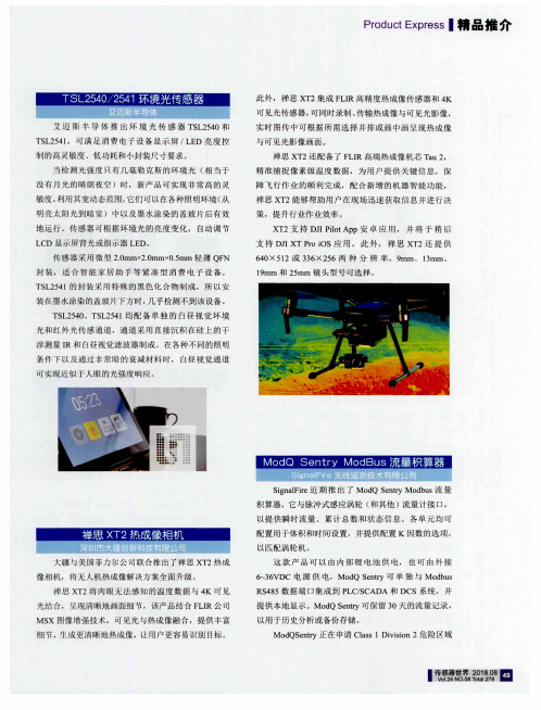
传 感 器 采 用 微 型 2.0mmx2.0mmx0.5mm 轻 薄 QFN 封 装 , 适 合 智 能 家 居 助 手 等 紧 凑 型 消 费 电 子 设 备 。 TSL2541的 封 装 采 用 特 殊 的 黑 色 化 合 物 制 成 ,所 以 安 姨在墨水涂染的盖玻片下方时,几乎检测不到该设备 。
TSL2540、TSL2541均 配备单 独 的 白昼视 觉环 境 光和 红 外 光 传 感 通 道 ,通 道 采 用 直 接 沉 积 在 硅 上 的 干 涉 测 量 lR 和 白昼 视 觉 滤 波 器 制 成 。在 各 种 不 同的 照 明 条件 下以及通过非 常暗的衰减材料 时, 白昼视觉 通道 可 实 现 近 似 于 人 眼 的光 强 度 响 应 。
Product Express_精 品推介
艾 迈 斯 半 导 体 推 出 环 境 光 传 感 器 TSL2540和 TSL254l, 可 满 足 消 费 电 子 设 备 显 示 屏 /LED 亮 度 控 制 的 高 灵敏 度 、低 功 耗 和 小封 装 尺 寸 要 求 。
当 检 测 光 强度 只 有 几 毫 勒 克 斯 的 环 境 光 (相 当于 没 有 月 光 的 晴 朗 夜 空 )时 ,新 产 品 可 实 现 非 常 高 的 灵 敏 度 。利 用 其 宽动 态 范 围 ,它 们 可 以在 各 种 照 明 环 境 (从 明 亮 太 阳 光 到 暗 室 ) 中 以及 墨 水 涂 染 的 盖 玻 片 后 有 效 地运 行。传 感器可根据环境 光的亮度变 化, 自动调 节 LCD 显 示 屏 背 光或 指 示 器 LED。
Panasonic SD-YR2540松下面包机中文说明书

Panasonic SD-YR2540松下面包机中文说明书1、面包桶从Panasonic SD-YR2540松下Panasonic SD-YR2540松下面包机中取出,把搅拌刀安装好。
2、倒入水之类的液体,要温热一些。
3、加入色拉油面包的做法,手把手教学,学会为止。
4、在面包桶的一角倒入盐,在另外一角倒入糖。
5、倒入一个鸡蛋6、加入面粉,面粉要覆盖住水面。
7、在面粉上按出一个小洞,里面倒入酵母。
8、把面包桶安装到Panasonic SD-YR2540松下面包机上,插上电源。
9、选择程序,按下启动键。
10、Panasonic SD-YR2540松下面包机开始揉面。
11、盖上Panasonic SD-YR2540松下面包机盖子,接下来就是等着Panasonic SD-YR2540松下面包机自己完成任务了。
12、先在面包桶里倒入液体,加入调味料,盐、糖等。
13、倒入面粉,覆盖住水面,在面粉上按一小洞,倒入酵母粉。
13、把面包桶安装到Panasonic SD-YR2540松下面包机上,插上电源。
按下启动键。
14、Panasonic SD-YR2540松下面包机开始揉面。
Panasonic SD-YR2540松下面包机搅拌一段时间后会自动停下来,这时按住“启动/停止”键三秒钟,结束此程序。
否则面团会开始发酵的。
15、加入软化的黄油,再次重复使用“发面团”程序,直到面团达到扩展状态。
16、面团揉好后,接下来就是面团的发酵了,不用把面团取出,留在Panasonic SD-YR2540松下面包机里就可以,盖上盖子,发酵至原来的两倍大,用手指沾面粉,在面团上戳一个洞,洞口不会回缩就说明已发酵完成。
17、发酵之后,把面团取出,就可以按照制作面包的正常程序来制作了。
一般的程序是排气——整型——二次发酵,再用烤箱来烤,这样经过二次发酵的面包会更松软更好吃。
ISD2540资料

ISD2532/40/48/64
SINGLE-CHIP, MULTIPLE-MESSAGES, VOICE RECORD/PLAYBACK DEVICE 32-, 40-, 48-, AND 64-SECOND DURATION
-1-
Publication Release Date: June 2003 Revision 1.0
VCCA
VSSA VSSD VCCD
A0 A1 A2 A3 A4 A5 A6 A7 A8
PD
OVF
P/R
CE
EOM
AUX IN
-3-
Publication Release Date: June 2003 Revision 1.0
元器件交易网
ISD2532/40/48/64
2. FEATURES
• • • • • • • •
Single 5 volt power supply Single-chip with duration of 32, 40, 48, or 64 seconds. Easy-to-use single-chip, voice record/playback solution High-quality, natural voice/audio reproduction Manual switch or microcontroller compatible Playback can be edge- or level-activated Directly cascadable for longer durations Automatic power-down (push-button mode) - Standby current 1 µA (typical) Zero-power message storage - Eliminates battery backup circuits Fully addressable to handle multiple messages 100-year message retention (typical) 100,000 record cycles (typical) On-chip clock source Programmer support for play-only applications Available in die form, PDIP, SOIC and TSOP packaging Temperature options: die (0°C to +50°C) and package (0°C to +70°C)
CXD2540Q-2中文资料

元器件交易网
元器件交易网
元器件交易网
元器件交易网
元器件交易网
元器件交易网
元器件交易网
元器件交易网
元器件交易网
元器件交易网
ห้องสมุดไป่ตู้
元器件交易网
元器件交易网
元器件交易网
元器件交易网
元器件交易网
元器件交易网
元器件交易网
元器件交易网
元器件交易网
元器件交易网
元器件交易网
元器件交易网
元器件交易网
元器件交易网
元器件交易网
元器件交易网
元器件交易网
元器件交易网
元器件交易网
元器件交易网
元器件交易网
元器件交易网
元器件交易网
元器件交易网
元器件交易网
元器件交易网
元器件交易网
元器件交易网
元器件交易网
元器件交易网
元器件交易网
元器件交易网
元器件交易网
元器件交易网
元器件交易网
元器件交易网
元器件交易网
元器件交易网
元器件交易网
元器件交易网
元器件交易网
元器件交易网
元器件交易网
元器件交易网
元器件交易网
激光器驱动电路中英文翻译
中文2540字Laser driver circuitSmall changes will directly semiconductor laser drive current to the output intensity fluctuation. To stabilize the output power semiconductor laser, V oltage negative feedback principle to design a constant current driving circuit comprises a soft starting and current limiting protection circuit based on; At the same time, according to the need of the light source is modulated to eliminate the influence of background light and, integrated laser modulation circuit comprises a crystal oscillation circuit and divider circuit design. Making the specific circuit and complete the relevant experimental. The experimental results show that the circuit can provide a driving current of high stability, Current stability up to 0.05%; Soft start and current-limiting protection circuit can protect the semiconductor laser and enhance the impact capability. Modulation circuit generates a carrier signal needed for laser diode modulation and direct to complete the output light modulation, The switch can be conveniently realized from 256Hz to 512kHz range of 12 kinds of commonly used modulation frequency selection.Semiconductor laser with its excellent characteristics, high efficiency, simple structure, small is widely used in scientific research, national defense, medical, and other areas of processing, its drive technology becomes more and more important. Semiconductor laser is the ideal electron - photon direct conversion devices, quantum efficiency is very high, the current small changes will lead to a great change, the output light intensity of the therefore, semiconductor laser drive current requirements is very high. Driving technology of semiconductor laser usually adopts constant current drive mode, this work, through the principle of negative feedback control loop, directly provide the effective control of the drive current. In addition, the transient current or voltage spikes, and overcurrent, overvoltage will damage the semiconductor laser drive circuit, therefore should be considered in the protection circuit against electric shock measures and special.In some applications, DC semiconductor lasers produce DC drive light in the measurement process is vulnerable to interference from ambient light slow change, which could not be separated from the environment light required DC optical signal, the signal-to-noise ratio is too small, so to carry on the modulation. When the high-speed modulated semiconductor lasers, there will be dynamic characteristics iscomplex, such as the relaxation oscillation, since the pulse and multi-pulse phenomena. In this paper, experiments were conducted to study the characteristics of low frequency modulation. Semiconductor laser output is stable, and can be directly modulated, it has been widely applied in optical system, is the preferred source sensor system. This paper describes the design of a high stability driving current, modulation, simple operation and low cost driving circuit for the light source of optical fiber systems.In this paper, the design of driving the semiconductor laser modulation circuit composed of four parts, including constant current circuit, a soft start, current limit protection and modulation signal generating circuit. The constant current circuit to generate a high stable drive current. Soft start is the role of eliminating surge may be present in the circuit, to prevent the harm of surge for laser. To avoid damage due to overcurrent caused by semiconductor laser can not be restored, then adding current-limiting protection in a driver circuit. Circuit to realize the modulation and frequency can be adjusted to generate a modulated signal.The constant current circuit is shown in figure 1, The in-phase end voltage reference Vr into A1 op amp, the operational control amplifier conducting level, and thus to obtain the corresponding output current. The output current generated by sampling voltage sampling resistor Rs, the sampling voltage is amplified as the inverting input voltage feedback voltage feedback amplifier A1, and voltage and the in-phase input end of comparison, Q2 to adjust the output voltage through the triode, adjustment and output current of semiconductor lasers, so that the whole closed-loop feedback system in the dynamic balance.AFigure 1 Constant current mapBecause the switch instantaneous in power supply generates a voltage, current surge, as well as the surge interference effects are likely to cause the breakdown andthe damage of the semiconductor laser, and therefore must be in the design of soft start circuit drive laser, namely the use of the charge and discharge of RC circuit, delay time, the specific circuit as shown in Figure 2 as shown in. Switch S1 is closed, the current through the resistor R1 and capacitor C3 to charge, the base electrode of the triode Q voltage gradually rises. As the capacitor charging and the conduction of the triode, output voltage V o is achieved from 0 to the maximum rise slowly, until the capacitor charge saturation, the voltage and current stabilizing. When the power supply is disconnected, the process of reverse, so as to realize the current and voltage decreases slowly.Figure 2 Soft start circuit diagramLaser soft start time and the charging capacitor and the corresponding resistance, when the capacitor charging tends to saturation, the output voltage soft start circuit can achieve maximum. Power supply voltage is V I, the capacitor voltage is V o, the capacitor charging formula:1(1)RC iV V e-=-According to this formula can calculate the electric charge and discharge time.Semiconductor laser with other devices, have normal working current, if the current exceeds this range, the laser will be damaged, therefore must restrict current laser in the set range.Emitter voltage transistor Q2 as the feedback voltage terminal phase in A3 op amp, when the feedback voltage is less than the limit voltage V, A3 op amp output low level, the transistor Q1 is turned on, this time by a triode Q2 output voltage feedback voltage is greater than the limit; when the voltage of V, A3 op amp output high, triode Q1 cutoff, this limits the triode Q2 emission increases very current, and is limited to a specific value. So even if the current caused by Vr control voltage exceeds the setvalue, the triode Q1 and Q2 are connected in series, so the total current will be clamped in the setting current value.Modulation signal generating circuit is composed of a crystal oscillating circuit and divider circuit is composed of two parts, used to generate the high stability of frequency, duty cycle square wave signal is stable. Crystal oscillating circuit directly generated by the active oscillator, oscillation frequency is 1MHz. Frequency divider circuit composed of a CMOS integrated circuit 4040.1MHz pulse signal after the frequency by 4040, pin output frequency from the switch is selected, the duty cycle is 50%, amplitude is 5V square wave signal. The modulation frequency dividing frequency were 256Hz, 512Hz, 1kHz, 2kHz,4kHz,8kHz,16kHz,32kHz, 64kHz128kHz, 256kHz, 512kHz..Driving an important technical parameters of circuit for current stability. Current stability is in a certain period of time, several measurements through the current size of the semiconductor laser, namely the ratio of output current stability for the relative change amount and input current, stability calculation, there will be current relative change is defined as the measurement of the maximum and minimum values, will measure the average value as the input current value.Drive circuit based on voltage negative feedback principle, by constant current drive mode to realize the control of the injection current and output power of semiconductor laser, and it can provide high stable output current, current stability 0.05%. Drive circuit with soft start, current limit circuit protection, reduce the damage of semiconductor laser to surge breakdown and current, the modulation circuit and the drive circuit effectively combined, realize the frequency is, the development of new technology of optical fiber communication is essential.The causes of dispersion: One is the light emitted by the light source is not monochromatic light; two is the modulation signal has a certain bandwidth.The dispersion of the classification: By different modes or different frequency (or wavelength) light signal components, transmission in optical fibers, due to the physical phenomenon of different group velocities cause signal distortion is called fiber dispersion. The fiber dispersion is divided into mode dispersion (or intermodal distortion), material dispersion and waveguide dispersion. After two kinds of dispersion is the dispersion a pattern, also known as intra-modal dispersion.Dispersion harm: Fiber dispersion in optical signal waveform distortion, performance for the pulse width, it is the time domain characteristics of optical fiber.In digital communication system, pulse broadening of optical signal is an important index. Pulse broadening is too large can cause adjacent pulse gap decreases, the adjacent pulse will overlap and regenerative repeater decision errors occur, which increases the BER, transmission bandwidth narrowing, limit the transmission capacity of optical fiber.Said method of dispersion: Commonly used dispersion representation has maximum time delay for $S, pulse width R and optical bandwidth of 3dB B three. The maximum time delay difference delay description fiber in the fastest and most slow wave component. Used to describe the effect of fiber dispersion on the transmission signal pulse broadening and optical fiber bandwidth. A section of optical fiber as a network analysis of the dispersion characteristics, the available time domain method and frequency domain method. When in the time domain analysis, dispersion effect is represented by the pulse broadening, and analyzed in the frequency domain, the transmission bandwidth said.激光器驱动电路半导体激光器驱动电流的微小变化将直接导致其输出光强的波动。
HA-2540资料

CAUTION: Stresses above those listed in “Absolute Maximum Ratings” may cause permanent damage to the device. This is a stress only rating and operation of the device at these or any other conditions above those indicated in the operational sections of this specification is not implied.
Refer to Application Note AN541 and Application Note AN556 for more information on High Speed Op Amp applications. HA-2540/883 MIL-STD-883 data sheet is available on request.
25
10
15
-
10
15
-
Full
5
-
-
5
-
-
Common-Mode Rejection Ratio (Note 4) Full
60
72
-
60
72
-
Minimum Stable Gain
25
10
-
-
10
-
-
Gain Bandwidth Product (Notes 5, 6)
25
-
400
-
-
400
-
OUTPUT CHARACTERISTICS
TI低功耗蓝牙BLE4.0射频片上系统CC2540中文数据手册

WISDOM FUTURE WIRELESS WORLD
智慧未来 无线世界
信驰达简介
信驰达科技(RF-star)是一家集合方案设计功能和核心器件供应的专业本地电子元器件分销商,专注低功 耗射频 LPRF 和低功耗 MCU 领域,公司成立于 2010年,作为中国区唯一具有美国 TI 公司授予的 LPRF Product Reseller 和 Third Party 双重资质的公司,一直引领着 LPRF 技术在国内的推广和应用,是国内唯一 一家可提供 LPRF 软硬件产品、技术支持、解决方案和核心元器件供应一条龙服务的专业化公司;
Shenzhen RF-star Technology Co.,Ltd. TEL: 0755-86329829 FAX:0755-86329413
WISDOM FUTURE WIRELESS WORLD
智慧未来 无线世界
This integrated circuit can be damaged by ESD. Texas Instruments recommends that all integrated circuits be handled with appropriate precautions. Failure to observe proper handling and installation procedures can cause damage. ESD damage can range from subtle performance degradation to complete device failure. Precision integrated circuits may be more susceptible to damage because very small parametric changes could cause the device not to meet its published specifications.
上海外国语大学虹口校区电话号码一览表
学科办公室
3109 教务办公室
3197 院办/学籍办
3122 副院长
2490 办公室
Байду номын сангаас
65871499 《国际观察》编辑部 2901 海外考试中心 2584、2877 电脑房
2731
英美文学研究中心 美国中心 基础教研室 高年级教研室
2604 2215
法语系
2328 主任/总支
2322 办公室
教师阅览室
2917 副主任室
2876、3167 综合部
2732、3063
院办 2326、 2433、2303 德语海外考试中心 2845 资料室
3273、2984 院办
3198 培养办
2813 书记
2487 办公室主任
56969765 院办公室
2618 办公室
3163、2880 财务部
3068
传真
35372556
3302、3332 英语组205.207 3278 德语. 俄语
2575 校长办公室 3159
288 65422770
院长、书记 学院办公室
2504、2940 2500、2652
西方语系
新闻传播学院
中文教研室3,4 语言学教研室
3195 研究生会 3193 会议室
2825 自考办 2809
2511、2509 招生办公室 35372954 教师办公室
3271 经营服务公司
机关总支
2873 阅览室
2467 人事档案
2803 教学科
2426 红十字会
2332 值班室
3266 青年楼办公室
宣传部
宣传部部长
多功能厅
2730 人才交流中心
- 1、下载文档前请自行甄别文档内容的完整性,平台不提供额外的编辑、内容补充、找答案等附加服务。
- 2、"仅部分预览"的文档,不可在线预览部分如存在完整性等问题,可反馈申请退款(可完整预览的文档不适用该条件!)。
- 3、如文档侵犯您的权益,请联系客服反馈,我们会尽快为您处理(人工客服工作时间:9:00-18:30)。
QUAD DARLINGTONPOWER DRIVERCombining AND logic gates and inverting high-current bipolaroutputs, the UDN2540B and A2540SLB quad Darlington power drivers provide interface between low-level signal-processing circuits andpower loads totaling 360 W. Each of the four independent outputs can sink up to 1.8 A in the on state with peak inrush currents to 2.5 A. The four power outputs are each comprised of an open-collector Darlington driver and an internal flyback/clamp diode for switching inductive leads. They feature a minimum breakdown and sustaining voltage of 50 V. The logic inputs are compatible with TTL and 5 V CMOS logic systems.Typical applications include print heads, relays, solenoids, and dc stepping motors. These drivers can also be used to drive high-current incandescent lamps, LEDS, and heaters. A similar device,specifically intended for driving a unipolar stepper motor in the two-phase drive format, is the UDN2544B.The UDN2540B is supplied in a 16-pin batwing power DIP; the A2540SLB is supplied in a 20-lead batwing power SOIC for surface-mount applications. The batwing construction provides for maximum package power dissipation in a standard construction. At 25°C, and with only 1 sq. in. of copper foil at the ground tabs, either package is capable of safely dissipating more than 2 W.FEATURESI 1.8 A Continuous Output Current I Output Voltage to 50 VI TTL and 5 V CMOS Compatible Inputs I Efficient Input/Output PinningI Integral Transient-Suppression Diodes IReplaces L6221A and L6221CDData Sheet29317CAlways order by complete part number:Part Number Package UDN2540B 16-pin batwing DIP A2540SLB 20-lead batwing SOIC2540115 Northeast Cutoff, Box 15036Worcester, Massachusetts 01615-0036 (508) 853-********QUAD DARLINGTON POWER DRIVERTRUTH TABLEENABLEIN N OUT N H H ON —L OFF LXOFFX = Don’t care.ENABLE GROUND GROUND OUT 2KGROUNDGROUNDOUT 3OUT 4KOUT 1IN 1IN 2IN 4IN 3NOCONNECTION NOCONNECTIONDwg. PP-017-3NOCONNECTION NOCONNECTIONSUPPLY A2540SLB5075100125150510A L L O W A B L E P A C K A G E P O W E R D I S S I P A T I O N I N W A T T STEMPERATURE IN °C43225Dwg. GP-049-3Copyright © 1986, 1996 Allegro MicroSystems, Inc.2540 QUAD DARLINGTON POWER DRIVER LimitsCharacteristic Symbol Test Conditions Min.Typ.Max.Units Output Leakage Current I CEX V OUT = 50 V, V IN = 0.8 V, V EN = 2.4 V—<1.0100µAV OUT = 50 V, V IN = 2.4 V, V EN = 0.8 V—<1.0100µA Output Sustaining Voltage V CE(sus)I OUT = 1.8 A, L = 3.0 mH50——V Output Saturation Voltage V CE(SAT)I OUT = 600 mA, V IN = V EN = 2.4 V—0.9 1.0VI OUT = 1.0 A, V IN = V EN = 2.4 V— 1.0 1.2VI OUT = 1.8 A, V IN = V EN = 2.4 V— 1.3 1.6V Input Voltage Logic 1V IN(1) or V EN(1) 2.4——VLogic 0V lN(0) or V EN(0)——0.8V Input Current Logic 1V IN(1) or V EN(1) = 2.4 V——10µALogic 0V lN(0) or V EN(0) = 0.8 V——-100µA Total Supply Current I CC V IN* = V EN = 2.4 V, V CC = 5.0 V,—1420mAOutputs OpenV IN* = V EN = 0.8 V, V CC = 5.0 V—0.4 2.0mA Clamp Diode Forward Voltage V F I F = 1.0 A— 1.3 1.6VI F = 1.8 A— 1.6 2.0V Clamp Diode Leakage Current I R V R = 50 V—<1.0100µA Typical Data is for design information only.Negative current is defined as coming out of (sourcing) the specified terminal.As used here, -100 is defined as greater than +10 (absolute magnitude convention) and the minimum is implicitly zero.*All inputs simultaneously, all other tests are performed with each input tested separately.ELECTRICAL CHARACTERISTICS at T A = 25°C, T J≤ 150°C, V CC = 4.75 V to 5.25 V.115 Northeast Cutoff, Box 15036Worcester, Massachusetts 01615-0036 (508) 853-50002540QUAD DARLINGTON POWER DRIVERAPPLICATIONS INFORMATIONA typical application is shown for driving four high-current relays,solenoids, or print heads. A Zener diode is used to increase theflyback voltage, providing a much faster inductive load turn-off current decay, resulting in faster dropout (reduced relay contact arcing), and improved performance. The maximum Zener voltage, plus the load supply voltage, plus the flyback diode forward voltage must not exceed the device ’s rated sustaining voltage.With external control circuitry, the ENABLE input can be used for chopper (PWM) applications. If the ENABLE input is not used, it should be tied high.All inputs will float high if open circuited.Dwg. WP-001O U T P U TV O L T A G EO U T P U TC U R R E N TV CCV I I2540QUAD DARLINGTONPOWER DRIVERNOTES:1. Leads 1, 8, 9, and 16 may be half leads at vendor ’s option.2. Lead thickness is measured at seating plane or below.3. Lead spacing tolerance is non-cumulative.4. Webbed lead frame. Leads indicated are internally one piece.5. Exact body and lead configuration at vendor ’s option within limits shown.Dimensions in Millimeters (for reference only)Dwg. MA-001-17A in18UDN2540BDimensions in Inches (controlling dimensions)Dwg. MA-001-17A mm1618115 Northeast Cutoff, Box 15036Worcester, Massachusetts 01615-0036 (508) 853-50002540QUAD DARLINGTON POWER DRIVERNOTES:1. Webbed lead frame. Leads 5, 6, 15, and 16 are internally one piece.2. Lead spacing tolerance is non-cumulative.3. Exact body and lead configuration at vendor ’s option within limits shown.Dwg. MA-008-21A mm1.27BSCNOTE 1NOTE 3A2540SLBDimensions in Inches (for reference only)Dwg. MA-008-21A inBSCNOTE 1NOTE 3Dimensions in Millimeters (controlling dimensions)2540 QUAD DARLINGTON POWER DRIVERThe products described here are manufactured under one or more U.S. patents or U.S. patents pending.Allegro MicroSystems, Inc. reserves the right to make, from time to time, such departures from the detail specifications as may be required to permit improvements in the performance, reliability, or manufacturability of its products. Before placing an order, the user is cautioned to verify that the information being relied upon is current.Allegro products are not authorized for use as critical components in life-support devices or systems without express written approval.The information included herein is believed to be accurate and reliable. However, Allegro MicroSystems, Inc. assumes no responsi-bility for its use; nor for any infringement of patents or other rights of third parties which may result from its use.115 Northeast Cutoff, Box 15036Worcester, Massachusetts 01615-0036 (508) 853-50002540QUAD DARLINGTON POWER DRIVERPOWER SINK DRIVERSIN ORDER OF 1) OUTPUT CURRENT, 2) OUTPUT VOLTAGE, 3) NUMBER OF DRIVERSOutput Ratings *FeaturesSerial Latched DiodeInternalmAV#Input Drivers ClampOutputsProtectionPart Number†75178X X –constant current –62751716X X –constant current –627610020 8–––saturat e d –25953032X X –––58334032X X –saturated –583250 8addr e ssabl e d e cod e r/driv e r DMOS –6B25950 8–X –DMOS –6B27350 8X X –DMOS –6B59525050 8addr e ssabl e d e cod e r/driv e r DMOS –625950 8–X –DMOS –627350 8X X –DMOS –6595135 7––X ––700330045 1–Hall sensor/driver X –X 514050 7––X ––200350 8––X ––280350 8––X saturat e d –259660 4––X saturated X 255795 7––X ––202395 8––X ––282335050 4–X X ––580050 7––X ––200450 8––X ––280450 8–X X ––580150 8X X –––582150 8X X X ––584150 8addr e ssabl e d e cod e r/driv e r DMOS –6A25950 8X X –DMOS –6A59580 8X X –––582280 8X X X ––584295 7––X ––202495 8––X ––28244503028dual 4- to 14-lin e d e cod e r/driv e r ––681760060 4–––saturated X 254760 4––X saturated X 254970060 4––X saturated X 2543 and 255975050 8––X saturat e d –259790014 2–Hall sensor/driver X saturated X 362526 2–Hall sensor/driver X saturated X 3626100046 4stepper motor controller/driver MOS –7024 and 7029120046 4microstepping controller/driver MOS –7042125050 4stepper motor translator/driver –X 580450 4––X ––2064 and 2068150080 4––X ––2065 and 2069180050 4––X ––254450 4––X ––2540300046 4stepper motor controller/driver MOS –702646 4microstepping controller/driver MOS –7044400050 4––X ––287880 4––X ––2879*Current is maximum specified test condition, voltage is maximum rating. See specification for sustaining voltage limits orover-current protection voltage limits.†Complete part number includes additional characters to indicate operating temperature range and package style.。