elecworks技术资料PDF
elecworks报告

企业工程实习与实训报告专业:电气工程及其自动化班级:电气1301姓名:李海龙学号:201309408指导教师:王思华兰州交通大学自动化与电气工程学院2016年11月9日1实习内容1.1 实习项目1时间:2016-9-10,10:00至12:00 地点:兰州交通大学一教224指导教师:赵峰实习内容:了解电气制图的基础知识、PLC电气控制设计的基本要求电气线路图是采用标准图形符号按一定的逻辑关系或功能顺序排列,表示系统、分系统、装置、部件、设备等实际电路的连接关系的一种简图。
一个电路通常由电源、开关设备、用电设备和连接线四个部分组成,如果将电源设备、开关设备和用电设备看成元件,则电路由元件与连接线组成,或者说各种元件按照一定的次序用连接线起来就构成一个电路。
可编程控制器的定义可编程控制器,简称PLC(Programmable logic Controller),是指以计算机技术为基础的新型工业控制装置。
PLC的特点1可靠性高,抗干扰能力强高可靠性是电气控制设备的关键性能。
PLC由于采用现代大规模集成电路技术,采用严格的生产工艺制造,内部电路采取了先进的抗干扰技术,具有很高的可靠性。
例如三菱公司生产的F系列PLC平均无故障时间高达30万小时。
一些使用冗余CPU的PLC的平均无故障工作时间则更长。
从PLC的机外电路来说,使用PLC 构成控制系统,和同等规模的继电接触器系统相比,电气接线及开关接点已减少到数百甚至数千分之一,故障也就大大降低。
2配套齐全,功能完善适用性强PLC发展到今天,已经形成了大、中、小各种规模的系列化产品。
可以用于各种规模的工业控制场合。
除了逻辑处理功能以外,现代PLC大多具有完善的数据运算能力,可用于各种数字控制领域。
近年来PLC的功能单元大量涌现,使PLC 渗透到了位置控制、温度控制、CNC等各种工业控制中。
加上PLC通信能力的增强及人机界面技术的发展,使用PLC组成各种控制系统变得非常容易。
Elenco TM Electronics XP-620K 电源模块模型说明书

Assembly and Instruction ManualQty.Description Part#1Transformer4407201PC Board5120131Fuse 1.25A5301251Rocker Switch5412041Cover6111201Chassis6120201Heat Sink6150102Knob6220091Strain Relief6240035Insulating Washer6240074PC Board Stand-off6250012Black Binding Post6250315Lockwasher, Binding Post625031LW5Nut, Binding Post625031HN2Red Binding Post6250321Y ellow Binding Post6250345Screw 6-32 x 3/8”Phillips6416402Screw 8-32 x 3/8”Phillips6418404Screw #6 x 3/8”Black T russ Head6426522Screw #6 x 3/8”black AB Phillips6426602Nut 7mm644101Qty.Description Part#1Nut 6-32 Large6446004Nut 6-32 Small6446012Nut 8-326448002Flat Washer 8mm x 14mm6451012Lockwasher 5/16”6461012Lockwasher #86468284Rubber Feet6620031Fuse Holder Body663005LB1Fuse Holder Nut663005N1Fuse Holder Cap663005UB1Fuse Holder Washer663005W3Mica Insulator7800021Silicon Grease7900056”20 Ga.Red Wire81321048”22 Ga.Red Wire81420148”22 Ga.Orange Wire81431048”22 Ga.Blue Wire8146101Line Cord8621052”Shrink T ubing 1/2”Dia.8911011.5”Shrink T ubing 3/4”Dia.8991101Solder T ube9ST4Transformer FuseHeatsink Switch Strain ReliefPC Board Stand-offBinding Post Assembly Fuse AssemblyFlat Washer LockwashersMica Nuts 7mm6-32 / 8-32#85/16”Binding PostLockwasherNut.18W 3W ResistorBANDSIDENTIFYING CAPACITOR VALUESCapacitors will be identified by their capacitance value in pF (picofarads), nF (nanofarads), or capacitors will have their actual value printed on them.Some capacitors may have their value printed in the following The maximum operating voltage may also be printed on the capacitor.For the No.01234103K100VThe value is 10 x 1,000 = 10,000pF or .01m F 100V10m F 16VMETRIC UNITS AND CONVERSIONSMultiply Unit By Or .00000000000110-1210-910-610-3100103106IntroductionThe most important factor in assembling your XP-620K Power Supply Kit is good soldering ing the proper soldering iron is of prime importance. A small pencil type soldering iron of 25 - 40 watts is recommended.The tip of the iron must be kept clean at all times and well tinned.Safety Procedures•Wear eye protection when soldering.•Locate soldering iron in an area where you do not have to go around it or reach over it.•Do not hold solder in your mouth.Solder contains lead and is a toxic substance.Wash your hands thoroughly after handling solder.•Be sure that there is adequate ventilation present.Assemble ComponentsIn all of the following assembly steps, the components must be installed on the top side of the PC board unless otherwise indicated.The top legend shows where each component goes.The leads pass through the corresponding holes in the board and are soldered on the foil e only rosin core solder of 63/37 alloy.DO NOT USE ACID CORE SOLDER!Solder Soldering IronFoilSolder Soldering IronFoilComponent Lead Circuit BoardFoilRosinSoldering iron positioned incorrectly.SolderGapComponent LeadSolderSoldering IronDragFoil 1.Solder all components from the copper foil side only.Push the soldering iron tip against both the lead and the circuit board foil.2.Apply a small amount of solder to the iron tip.This allows the heat to leave the iron and onto the foil.Immediately apply solder to the opposite side of the connection, away from the iron.Allow the heated component and the circuit foil to melt the solder. 1.Insufficient heat - thesolder will not flow onto the lead as shown.3.Allow the solder to flow around the connection.Then, remove the solder and the iron and let the connection cool.The solder should have flowed smoothly and not lump around the wire lead.4.Here is what a good solder connection looks like.2.Insufficient solder - let thesolder flow over the connection until it is e just enough solder to cover the connection.3.Excessive solder - couldmake connections that you did not intend to between adjacent foil areas or terminals.4.Solder bridges - occurwhen solder runs between circuit paths and creates a short circuit.This is usually caused by using too much solder.To correct this,simply drag your soldering iron across the solder bridge as shown.What Good Soldering Looks LikeA good solder connection should be bright, shiny,smooth, and uniformly flowed over all surfaces.Types of Poor Soldering ConnectionsElectrolytics have a polarity marking indicating the (–) The PC board is marked to show the lead position.Mount the transistor with the flat side as shown on the top legend.Leave 1/4”between the part and PC board.BandD4 - 1N4001 DiodeD3 - 1N4001 DiodeD2 - 1N4001 DiodeD1 - 1N4001 Diode(see Figure A)R2 - 150W ResistorR1 - 150W Resistor(–) (+)0123Use this ruler to measure the wires when cutting them to their required lengths.4567Press knobs onto the shaft of the Push the switch into the hole in the Figure DLug 1LockwasherNut RedBlack Y ellow Rear View of Rocker Switch7mm Nuts8mm Washers5/16”LockwashersPotentiometers* Cut off tabsRedBlack INC R E A S Eon the back of the transistor and ICs.Install IC3 as shown in Figure Fa.Mount the fuse holder to the top hole in the back of the chassis,with the side lug up, as shown in Figure G.Fasten in place with After the holder is secure, insert the fuse and Separate the wires of the line cord 3”from the end.Strip the insulation off the end of all three wires to expose 1/4”of bare wire.of the line cord into the bottom hole on the back Place the line cord into the slot of the strain relief and squeeze the two Then, insert the strain relief One side of the transformer has only 2 black wires.Cut in length (see Figure H).Cut the red, blue and black wires on the other side of the transformer so that they are 3”in length.Strip the insulation off the end of the wires to expose 1/4”of bare wire.Cut the yellow wires flush with the transformer.Install the transformer with the black wires side as shown in Figure e an 8-32 x 3/8”screw, #8lockwasher and an 8-32 nut on each side to fasten in place, as shown in Figure I.Figure ELM7805LM-337LM-3172N6124MicaSmall 6-32 NutIC1, IC2,Heat SinkInsulator Washer6-32 x 3/8”ScrewSilicon Grease MicaFigure FaSmall 6-32 NutIC3LM7805Heat SinkInsulator Washer 6-32 x 3/8”ScrewInsulator WasherFigure GRibbedSmooth 1/4”Figure I8-32 x 3/8”ScrewFigure H4”Red 4”Red 4”Blue4 1/2”BlackSide LugPliersFuse HolderFuseCapWasherNut4”Blue4”BlackFigure JChassisSide Lug End LugSmooth Line CordFlat or Ribbed Line Cord123(A) BlackRed Red 2”TubingY ellow Y ellowRibbed Line CordBlue Black Blue(B) Black 6”20 Ga.Red J K T 2T 2T 1C T 1T 1W V U 3/4”ShrinkT ubing 6-32 x 3/8”Screw 6-32 Large NutFigure KLM-317LM-337I H GDCBlack Post6”Red6”Blue3”RedRed PostBlack PostY ellow Post3”Orange3”BlueRed wire (W) from PC board;To middle lead of LM-317.Orange wire (S) from PC To left lead of LM-317.Blue wire (U) from PC board;To right lead of LM-317.Red wire (R) from PC board;T o middle lead of LM-337.Blue wire (T) from PC board;T o left Orange wire (V) from PC board;To right lead of LM-337.be sure that none of the leads touch each other and Red Post4 1/2”Blue5”Orange 4 1/2”Red 5”Blue 4 1/2”Orange 5”Red E L E N C O E L E C T R O N I C S I N C .X P -6204”Blue 4”Red EF JK 4”Red 4”Orange Negative VoltagePositive VoltagePotentiometersFigure LQ P O N M L 2N61247805Bottom View Figure M6 x 3/8”ScrewsFeetFeet 6 x 3/8”Screws Truss Head 6 x 3/8”Screws Truss HeadBy addition of a second diode and transformer winding, we can fill in the gap between cycles as shown in Each diode conducts when the voltage is positive.By adding the two outputs, the voltage presented to capacitor C5 is more complete, thus easier to filter, as shown When used in 60 cycles AC input power, the output of a full wave rectifier will be 120 cycles.Capacitor C5 is used to store the current charges, thus smoothing the DC voltage.The larger the capacitor, the F capacitors are used, which allows about 3 volts AC ripple when Figure 3Figure 4Figure 2A)Transformer Winding AB B)Transformer Winding BC C)Output of diode D1.D)Output of diode D2.E)Total of diodes D1 & D2.20VF)Output of capacitor C1Ripple depends on load current (expanded).Half Wave RectifierFull Wave RectifierTherefore, the The 1N4001 has peak current rating of 10 amps.The regulator circuit in the Model XP-620 Power Supply consists of a LM-317 integrated circuit.This IC is Figure 6 shows a simplified circuit of how the LM-317 IC Another feature of the LM-317 regulator is to protect the IC against overload and output shorts.If the IC is A transistor will sense this overheating and shut Figure 5Figure 620V Peak 20VOutput R1R2DividerQ1Q21.5VQ3Q4Q5Current Source Equalized to 1 Meg.LM-3172 - 15VR1VR1Figure 6AThe theory of the negative voltage regulator is the same as the previously discussed positive regulator. basic differences is that diodes D2 and D4 are reversed, producing a negative voltage across capacitor C6.In the previous discussion of the variable voltage regulators, the ICs can handle about 1A of current.To meet this current requirement we must add an external passFigure 7If the output is shorted to groundThe LM-7805 IC will only draw the .2A it wasAnother transistor Q1 is added to limit maximum current.When approximately 3A is drawn in transistor Q2,This will force more current in the LM-7805 IC. Eventually the LM-7805 IC will overheat turning itself off and thus limiting the circuit at about 3.2A.SPECIFICATIONS ON XP-620 POWER SUPPL YElenco TM Electronics,Inc.150 W.Carpenter AvenueWheeling, IL 60090(847) 541-3800e-mail:*****************。
英赛威产品手册版

KZ释放电压
VDC
KZ电流
mA
GND
正常工作功耗
W
工作电压范围VDC
最低电压
最高电压
12V
5V-12V
2V-0V
>5mA
与电源共地
<2W
9V
15V
注意:1.供电电源要求:DC +12V0.5A电源纹波:≤50mV继电器电源端并联电解电容≥1000UF。
2.本继电器在带载中不允许直接断开电源,否则会造成继电器的损坏!
4.1 P3V30系列(300V,10-30A,12V线圈电压,一组常开,PCB规格)9
4.2 P3V20系列(300V,10-20A,12V线圈电压,双刀单掷,PCB规格)10
五、400VDC继电器………………………………………………………………..11
5.1N4V40系列(400V,10-40A,12V线圈电压,一组常开)………..….11.
第二个字母代表同等电压,电流的第几套模具,A代表第一套,B代表第二套等。
后面两个数字表示该系列最大电流,如70表示最大电流70A。
最后一个字母代表触点型式及线圈电压,A代表12V线圈电压及一组常开型,B代表12V线圈电压及二组常开型。
三、200VDC继电器
P2V80系列性能介绍
P2A40A/P2A60A/P2A80A
二、产品命名规则
我司继电器产品比较多,因此我司产品按不同电压分为各种系列,每个系列下再包含几个产品,因此命名规则分为系列命名和产品命名两种。
系列命名规则如下(以P6V70为例):
P6V70
第一个字母代表继电器的规格,P表示线路板引出端规格,N表示常规规格。
第一个数字和第二个字母代表直流电压,如6V表示600VDC。
电子旋转电机技术数据1449说明书

† UL File XAPX.E108966Fire & Smoke damper actuator ApplicationThe type FSNF spring-return actuator is intended for the operation of smoke and combination fire and smoke dampers in ventilation and air-conditioning systems. The actuator will meet requirements of UL555 and UL555S when tested as an assembly with the damper and will meet requirements of UBC for 15 second opening and closing at 350°F. Square footage of damper operated will depend on make and model and the temperature required.OperationMounting of the actuator to the damper axle shaft or jackshaft (3/8” to 1.05”) is via a cold-weld clamp. Teeth in the clamp and V-bolt dig into the metal of both solid and hollow shafts maintaining a perfect connection. The specially designed clamp will not crush hollow shafts. The bottom end of the actuator is held by an anti-rotation strap or by a stud provided by the damper manufacturer.The actuator is mounted in its fail safe position with the damper blade(s) closed. Upon applying power, the actuator drives the damper to the open position. The internal spring is tensioned at the same time. If the power supply is interrupted, the spring moves the damper back to its fail-safe position.actuators draw higher peak current when driving against any type of stop. If used, this requires the value of a local fuse or breaker to be increased to avoid nuisance opening or tripping. A 2.5 amp slow blow should be used for 24VAC. A 0.5 amp slow blow should be used for 120 VAC. A 0.25 amp slow blowshould be used for 230V and a 0.3 amp slow blow for 208 VAC. Transformers: Note that while a 24V 100VA transformer would handle 2 actuators, a 4 A breaker or plug fuse is insufficient. A 5 amp slow blow would be required.Belimo Fire & Smoke actuators have passed the AMCA 520 and UL 555S Long Term Holding test. No special cycling is required during prolonged periods when actuator is driven open and held there. Periodic testing of dampers and actuators per local codes and NFPA 80 and NFPA 105 are required.The actuator contains no components which the user can replace or repair. A 1/2” threaded connector is standard. FSNFxx-FC models have a 3/8” Flex Connector. Other than the connector, these actuators are identical to the conduit connector version.FSNF120-S USOn/Off, Spring Return, 350°F [177°C] for half hour, 120VAC, 15 Seconds Cycle TimeD a t e c r e a t e d , 12/14/2015 - S u b j e c t t o c h a n g e . © B e l i m o A i r c o n t r o l s (U S A ), I n c .71818-00001Typical SpecificationAll smoke and combination fire and smoke dampers shall be provided with Belimo FSTF, FSLF, FSNF, or FSAF actuators. All substitutions must be approved before submission of bid. Damper and actuator shall have UL 555S Listing for 250°F (350°F). Actuator shall have been tested to UL 2043 per requirements of IMC 602.2 and NEC 300.22 (c). Where position indication is required -S models with auxiliary switches or damper blade switches will be provided per code requirements.Provide overload protection and disconnect as required.45Actuators may be powered in parallel. Power consumption must be observed.72S4 makes to S6 when actuator is powered open.73Auxiliary switches are for end position indication or interlock control.74Double insulated.75Ground present on some models.FSNF120-S USOn/Off, Spring Return, 350°F [177°C] for half hour, 120VAC, 15 Seconds Cycle TimeD a t e c r e a t e d , 12/14/2015 - S u b j e c t t o c h a n g e . © B e l i m o A i r c o n t r o l s (U S A ), I n c .。
elecworks介绍

技术介绍
讲义大纲
1. 公司介绍 2. 什么是电气设计? 3. 丏业电气CAD的发展 4. elecworks功能亮点及优势 5. elecworks与AutoCAD的区别 6. elecworks客户案例 7. elecworks 完整操作演示 8. elecworks入门实训
Trace Group 集团公司
面对挑战
-设计效率低,质量差 -无法集成电气与机械数据 -企业信息化进程受阻
elecworks给而客户带来的好处
-检查图纸错误率,提高图纸标准化程度 -将电气设计与机械设计集成 -加快企业信息化发展步伐
“星火机床始终走在企业信息化管理的 前列,有了elecworks我们才真正实现 了从电气到结构设计一系列的数据集成 和管理,给我们企业信息化带来了便 利。”
黄凯 电气部经理
中国石化江汉石油管理局第四机械厂 (四机厂) 是一家石油钻采装备研制企业。 四机厂在快移快装钻机、低温石油装备、自 动混浆水泥车、大功率压裂机组研制领域达 到国际领先水平。
面对挑战
-电气无法满足企业标准化设计要求 -电气、固压、钻修的原理图设计不规范 -液气系统无法与现有三维系统平台集成 -液气系统无法与企业PLM机械系统兼容
目前中国客户分布
设计工具的发展
图板设计
甩图版
机械设计
三维 设计
机电一体化
CAD
电气设计
电气模块化设计
电气设计流程的发展(1)
传统工具设计流程 (昨天)
2D原理图
2D布局图
清单统计
生产、计划、 采购、财务、
其他……
电气设计流程的发展(2)
专业工具设计流程 (今天)
2D 原理图
3D 布局图
万福乐比例电磁电技术说明

技术说明比例电磁铁用于液压系统目录1.前言2.电磁铁的类型3.术语说明3.1.力3.2.电压3.3.电阻3.4.电流3.5.电功率3.6.时间的表述3.7.函数3.8.迟滞3.9.线性度4.用途的类型1.前言技术说明旨在阐明和定义在电磁铁样本或阀样本中见到的与比例电磁铁有关的表述。
没有包含在该说明中的,然而出现在电磁铁或样本中的表述,可以在切换电磁铁的说明中找到。
2.电磁铁的类型直流比例电磁铁单行程电磁铁(压缩,轴向运动),在电磁铁力的作用下,它的衔铁完成行程运动,从初始行程位置至终端行程位置。
它与切换电磁铁是不同的,根据其作用,它是2-步位移/电流或力/电流作用。
要实现迟滞小和理想的线性度,也要注意下列要点:- 选择良好的电磁铁材料(电磁迟滞小;见3.1)- 理想的衔铁轴承系统(摩擦迟滞小)3.术语说明3.1.力电磁铁力(F M)力的有效部分(即减去摩擦),它是在行程方向(运动方向1)产生的;见图1。
额定力(F MN)在额定电流下达到的电磁铁力。
复位力(F MR)在电磁铁上的外部力,它是为了使电磁铁逆着行程方向(运动方向2)移动所必须施加的。
它是电磁铁力、二倍的摩擦力和迟滞力(见图2)之和,大于电磁铁力。
电感力(F F)通过电磁场,施加在衔铁上的机械力(见图1和图2)。
摩擦力(F u)该力的发生作为摩擦的结果。
通常是在运动方向的相反方向(见图1和图2)。
迟滞力(F HY)该力的发生作为电磁迟滞的结果(见图1和图2)运动方向1 运动方向2F M=F F-F u F MR=F F+F Hy+F u力迟滞(HF) (差动力)电磁铁复位力和电磁铁力之差(见3.8迟滞)F RM-F M=2F u+ F HY = H F3.2.电压电压是指算术平均值。
参考电压(U B)电磁铁上指示的电压,当最低达到最高静态温度时,它产生限定电流IG,作为供电电压它必须始终有效。
3.3.电阻额定电阻(R N)电磁铁线圈在20℃环境温度下的欧姆律电阻。
elecworks入门教程
方框图图纸 原理图图纸
方框图菜单 原理图菜单
但是,您可以用“绘图”菜单在您的图框中创建您自己的符号。
绘图菜单
在此菜单中您可以找到所有常用的绘图工具,以及插入文字,插入图片„ 所绘制的图形不包含任何电气特性。
方框图菜单
插入符号块,和绘制符号间的连接线。 插入图纸间的中断转移。 绘制功能和位置轮廓线。 编辑元件间的布线。
您可以看到制造商基准自动生成了元件回路(在对话框的底部可见)。这些回路也同
时存在符号里,当您把符号和制造商基准关联时,这些回路会根据匹配状态自动改变
颜色。
-
: 符号和制造商基准回路匹配
-
: 只含符号回路(不含制造商基准回路)
-
: 只含制造商基准回路(与符号回路不匹配)
13
PLC 管理器
elecworks允许管理任何种类的PLC:包括PLC模块或PLC机架或PLC控制卡。elecworks提 供两个功能,一个是管理PLC的结构,一个是管理PLC的输入输出(I/O)。 PLC图形将被自动绘制在页面上,您便可以完善它。
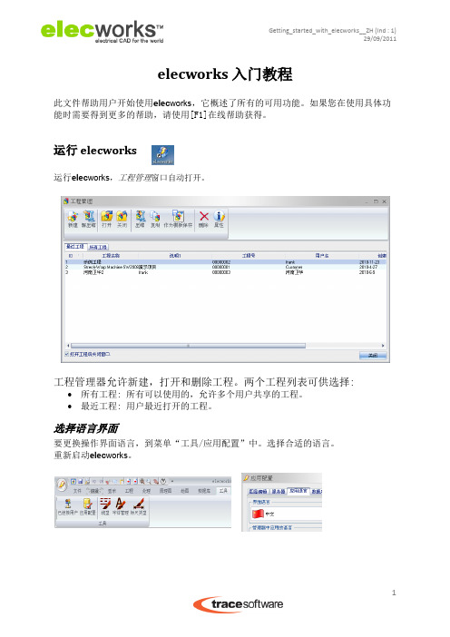
运行elecworks,工程管理窗口自动打开。
工程管理器允许新建,打开和删除工程。两个工程列表可供选择:
所有工程: 所有可以使用的,允许多个用户共享的工程。 最近工程: 用户最近打开的工程。
选择语言界面
要更换操作界面语言,到菜单“工具/应用配置”中。选择合适的语言。 重新启动elecworks。
处理菜单
清单的绘制和管理(图纸清单,元件清单,电缆清单„) 端子排图形的绘制和管理 线号 Solidworks 3D机柜布局 2D 机柜布局 工程翻译 工程文件导出 : DWG, PDF格式„
6
艾斯科 BD-50E高频发生器使用说明书

4642 N. RAVENSWOOD, CHICAGO, ILLINOIS 60640-4510TELEPHONE: 1-773-561-2349FAX: 1-773-561-3130Model BD-50E HIGH FREQUENCY GENERATOROPERATING MANUALDESCRIPTION. The Model BD-50E is a rugged tester designed for testing tank lining and other applications where extended use is necessary. The unit is operated by a transformer which limits the current and isolates the unit from the power line for safety protection. The low voltage (magnet coil) and high voltage (resonator coil) are separated, making the unit run cooler than the hand-held models. This also allows for an extended period of use, up to no more than about 3 hours of use, with a similar cool down period.It has a peak output voltage of between 20,000 to 50,000 V, ±2 kV, at a frequency of 0.5 MHz. The current output is approximately 1 mA.The Output Adjustment Knob is graduated from 1 to 11. The actual output voltage will vary depending upon the electrode used, as a larger electrode will load down the unit. Also, there is some variation in output from unit to unit, and will vary depending upon the condition of the vibration contacts inside the unit. Worn contacts will decrease the output. As a rule however, these are the approximate outputs that can be expected from a unit that is operating properly: POSITION N0. 1 3 5 7 9 11 Voltage 20,000 27,000 32,000 38,000 43,000 49,000Four models are available for different input voltages:Model BD-50E (SKU 15001), 115 V, 50/60 Hz, with 12101 Electrode Tip .Model BD-50EV (SKU 15021xx-10), 230 V, 50/60 Hz, with 12101 Electrode Tip. Model BD-50ET Tank Lining Tester Kit (SKU 15031), 115 V, 50/60 Hz, with 12101, 12131, and 12141 Electrode Tips. A carrying case is optional.Model BD-50EV Tank Lining Tester Kit (SKU 15061xx-10), 230 V, 50/60 Hz, with 12101, 12131, and 12141 Electrode Tips. A carrying case is optional.The 115 V model is also available equipped with a power line filter for use around sensitive electronic equipment (SKU 15001-10, and 15031-10).The “V” in the Model Number, BD-50EV, designates a line cord plug for use for 230 V input. The “xx” designates the line cord plug type furnished with models typically used outside of North America. All of these 230 V models are equipped with a power line filter.A 6 ft. (1.8 m) cable from the control box to the high voltage handle is provided with standard, but a longer cable, up to 15 ft. (4.5 m) can be special ordered. Contact Electro-Technic for specific details and ordering information. INSTALLATION. A standard tip electrode, Part No, 12101, illustrated above, but not below is included with each model. To install it, press it into the tip of the generator handle. To remove, grasp its base firmly, and with a gentle twisting motion, pull out from the generator tip. Never insert or remove the electrode while power is on.Accessory Electrodes for the Model BD-50E12111 Spring Tip12121 T-Tip12131 T-Tip, 12 in. Wide12141 Fan Tip12401 Brush Tip4 in. Wide 4 in. Wide12421 Brush Electrode, 8 in. WideThese electrodes, plus the 12101 Standard Tip, are the only factory approved electrodes for the Model BD-50E. No other electrodes should be used.After the electrode is inserted, plug the power line cord into its matching receptacle, providing the proper voltage for the unit, either 115 V or 230 V.OPERATION.1) Turn the Output Adjustment Knob fully counterclockwise, and then turnthe Power Switch to its ON position.2) Turn the Output Adjustment Knob clockwise to adjust the voltage forthe desired spark length. Hold the tip close to the chassis of the unit,or a common ground point, to observe and adjust the length of thespark. For thick materials, the spark should be adjusted for nearmaximum length. For very thin materials, a shorter spark is desired. Aone inch spark represents a peak voltage of approximately 50,000volts.3) When the tip is scanning close to a metal surface, there will be apurple color spark, or corona discharge glow.4) Once the unit is adjusted, pass the electrode over the material beingtested. The electrode can be passed directly over most materials,however, with thin linings, keep the electrode no more than 1/8 in.above the surface being tested.Photo at left shows a pin holelocated in a sheet of rubber,with a metal backing, using the12141 Fan Tip Electrode5) When the electrode passes over a pinhole, crack, or similar type flaw,observe a bright white, concentrated spark jumping from the electrodeto the metal, or similarly conducting surface below the lining or coating.A reprint of an article showing a flaw being detected is included withthese instructions.SAFETY PRECAUTIONS.It is used in industrial applications for pinhole leak detection, and toionize a gas inside a bulb or similar device to determine whether a goodvacuum is being held inside the device. It is also used as a lamp starter,principally in printing industry.Only factory approved electrodes should be used. No other electrodesshould be used with this device. Never operate without an electrode.Never touch or come in contact with the high voltage output of thisdevice, nor with any device it is energizing.Since its output is 500 kHz, it radiates its energy for a short distance.It may interfere with sensitive electronic devices near by. If a user iswearing a pace maker or similar device, their physician should becontacted prior to using this device. The same should be said forwomen who are pregnant.A small amount of ozone gas is generated as a by-product. Use in awell-ventilated area.Do not operate out of doors on in or around a flammable or explosiveenvironment.CALIBRATION SERVICE. Factory calibration service is available for a nominal charge. It includes test data for all output positions with a number of electrodes, and is traceable to a NIST standard. Yearly calibration is recommended. Request a Return Authorization Number prior to returning to the factory for calibration.MAINTENANCE / INSPECTIONS. If the output level of the Model BD-50E is required to be verified when this instrument is in use, check the output with a Model 12701 Peak Voltage Calibrator, shown below.The only component in this equipment that should be checked is the vibrating contacts that make and break the circuitry, generating the high frequency. These contacts, made of a tungsten alloy, erode with use. Eventually, they erode to a point where the output of the unit decreases.If the Model BD-50E receives light duty use, and is otherwise functioning properly, an annual inspection is recommended. If the unit is used on a frequent basis, has been dropped, or the maximum output is found to be decreasing, then a quarterly inspection is warranted.To check the contacts, with the power removed from the unit, remove the cover and visually check the contacts for carbon built-up, burn marks, excessive pitting or erosion. Also check that the contacts are aligned properly.To replace the contacts, remove the magnet coil assembly. Loosen the locking nut and back up the screw all the way back. Remove the top assembly and then remove the top contact and then the bottom contact assembly.Replace the bottom contact assembly, making sure that enough room is left between the bottom contact and the magnet coil top, so that the armature can vibrate freely, with about 0.035 to 0.040 in. clearance.Replace the top contact assembly, making sure that the two contact points will be aligned with each other when they are pushed together.Reinstall the top assembly and then the magnet coil assembly.CAUTION. Take precautions not to touch any wires, as power to beunit will have to be applied with the cover removed to perform thisoperation.To adjust the contacts use a screw driver to turn the adjusting screw to push the contacts until there is a spark between the contacts, the contacts are aligned, and that the armature is vibrating freely.Then tighten the nut, reinstall the screw cap and the cover.Recheck the output with the Model 1270 Peak Voltage Calibrator.If you should have any further questions, contact Electro-Technic Products, Inc. for additional technical assistance.TROUBLESHOOTING AND REPAIR. There are no user serviceable parts inside the unit. In the event that the unit requires service, send it back to the factory. However, parts are available separately, so an experienced electronics technician can make repairs. The following troubleshooting guide is furnished: Check all connections for loose or broken wires. If the pilot light does not come on, check for shorts and for input voltage at the fuse. If fuse is blown, replace it with a 3/4 A Slo-Blo for 115 V units, and ½ A Slo-Blo for 230 V units.If the fuse is Okay, check the power cord for shorts, and replace if necessary. Test the ON/OFF Switch.If the pilot light comes on, check the transformer for voltage between the secondary leads. If voltage is Okay, then check the magnet coil for resistance between 65 to 72 ohms for 115 V units, and 262 to 270 ohms for 230 V units. Check the contacts for the presence of a spark. If no spark, move the adjusting screw clockwise or counterclockwise. If the spark comes on, the unit is Okay. If not, check the printer circuit board for shorts and clean the contacts at the positions of the switch. If this does not solve the problem, replace the board. If the contacts of the magnet coil are working Okay, but there us still no output at the electrode tip, and the power supply to handle wire is Okay, then replace the resonator coil.REPAIR PARTS. The following are repair parts for the BD-50E models. Contact the factory for price and availabilityPart Number Description12101 Electrode Tip002-0005-1 Nut, 10-32, Hex, for Electrode Socket010-0003-1 Isolation Transformer, 115 V010-0012-1 Transformer, Step Down, 230 to 115 V011-0008-1 Magnet Coil011-0023-1 Choke Coil Assembly011-0024-1 Resonator Coil Assembly021-0053-1 Capacitor, 0.1 uF, 800 V023-0027-1 Power Supply / Generator Cord, 6 ft min., 15 ft. max025-7532-1 Printed Circuit Board Assembly025-0032-1 Printed Circuit Board027-0065-1 Power Line Filter028-0002-1 Pilot Light029-0002-1 Fuse Holder029-0024-3 Fuse, 1/2 A, Slow-Blow, for 230 V Models029-0030-1 Fuse, 3/4 A, Slow-Blow, for 115 V Models029-0085-1 Switch, Rotary, Heavy Duty033-0006-1 Cover, for Cabinet033-7005-3 Cabinet, without Cover035-0003-1 Top Spring Rivet Contact Assembly035-0017-1 Armature Assembly035-0008-1 Bridge, with Posts, Ratchet, and Adjusting Screws044-0003-1 Top Housing, Bakelite, Cone044-0004-1 Bottom Housing, Bakelite044-0007-1 Molded Spool Core044-0011-3 Adjusting Knob, w/Line045-0003-1 Electrode Socket049-0001-1 Cabinet Handle Assembly049-0025-1 Nut Driver, 5/16 in.050-0037-1 Tungsten Screw Contact050-0079-1 Cover Cap, Brass051-0001-1 Spacer, Teflon053-0003-1 Standoff, Nylon059-0040-1 Switch, Toggle, SPST, w/leads attached060-0002-1 Line Cord Set, 3 Conductor, 115 V060-000X-1 Line Cord Set, 3 Conductor, 230 V, Specify Type060-0100-1 Ribbon Cable Choke Assembly070-0059-3 Carton. Packing, with Insert080-1500-1 Handle Assembly (Resonator), with 6 ft. CordSpecial Note Regarding CE Marking. The Model BD-50EV generates a high voltage corona of approximately 500 kHz. However by the very nature of its design, it will produce electromagnetic interference (EMI) as a result of its operation. Electric arc welders, for example, are another product that by its very nature and mode of operation produces EMI.As a result, the Model BD-50EV cannot meet the European Union Electromagnetic Compatibility (EMC) Directive 89/336/EEC, and cannot be CE marked.It does, however, meet EN61010-1:1993 Safety Requirements for Electrical Equipment for Measurement, Control and Laboratory Use, following the provisions of the Low Voltage Directive 73/23/EEC, as amended by 93/68/EECBecause of the risk of EMI, a risk assessment should be carried out prior to use of this equipment.The power output of the Model BD-50EV is limited. The effective range of EMI is less than about 1 meter on so in all directions. Metal objects nearby may bend or deflect this radiation. Therefore, there is some risk that it might interfere with electronic equipment 1 meter or so from this apparatus. This might include telephones, computers, cell phones, for example. Operators who wear pacemakers may also wish to consult with a physician prior to using this equipment.If interference with equipment is detected, move the Model BD-50EV further away, or schedule its operation when the affected equipment is not in operation. Consult plant safety personnel regarding its use.If you should have any further questions, contact Electro-Technic Products, Inc. for additional technical assistance.。
- 1、下载文档前请自行甄别文档内容的完整性,平台不提供额外的编辑、内容补充、找答案等附加服务。
- 2、"仅部分预览"的文档,不可在线预览部分如存在完整性等问题,可反馈申请退款(可完整预览的文档不适用该条件!)。
- 3、如文档侵犯您的权益,请联系客服反馈,我们会尽快为您处理(人工客服工作时间:9:00-18:30)。
服务平台
公司网站: 电气设计技术交流QQ群: Elecworks电气设计软件群 93920038 专业电气设计软件群 19648935
引领机电一体化设计新方向
Thank you for your time!
更多信息请登陆
引领机电一体化设计新方向
电缆库
- 不同类型的电缆供用户选择 - 允许用户自定义编辑电缆库 - 电缆列表自动统计电缆长度
引领机电一体化设计新方向
elecworks 电气设计 2D模块
-确保您的设计质量 -全面提高您的设计效率 -大大缩短新产品设计周期 -提高图纸的标准化程度 -使您更专注于产品的开发与设计
项目管理
- 浏览数据库中所有工程项目 - 项目属性,标题栏等的编辑 - 将标准项目作为模板保存 - 将项目压缩便于交流 - 新建标准项目图纸
引领机电一体化设计新方向
文件管理
- 图纸预览 - 多类型的图纸文件 - 项目图纸以树状结构分类 - 允许添加任何类型的文件附件 - 右键菜单复制/粘贴,新建等功能
引领机电一体化设计新方向
elecworks 3D布局模块
-SolidWorks中管理所有项目
-SolidWorks中预览所有图纸
-实现在SolidWorks中管理所有图纸
引领机电一体化设计新方向
elecworks 3D布局模块
标准3D零件库 制造商产品库 (ABB,施耐德,西门子…) 根据电气元件尺寸及类型自动生成零件模型
引领机电一体化设计新方向
elecworks 的优势:
1. 2. 3. 4. 直观的操作界面,简单的操作方式 以数据库为核心的设计 实现整体项目管理 共享项目,协同工作
5. SolidWorks-elecworks实时共享数据库 6. 在SolidWorks中完成3D柜内布局 7. 在SolidWorks中完成3D柜内自动布线
引领机电一体化设计新方向
�
引领机电一体化设计新方向
elecworks 3D 柜体布局模块
- 与SolidWorks无缝集成 - 在SolidWorks中预览电气图纸,元件清单 - elecworks-SolidWorks同步共享数据库 - 电气部与机械部同时工作于同一项目
引领机电一体化设计新方向
elecworks 3D布局模块
引领机电一体化设计新方向
友好的操作界面
- 简体中文操作界面 - 支持放弃/恢复功能 - 图纸资料实时保存 - 用户自定义快捷键绘图 - 标准Windows风格操作方式
引领机电一体化设计新方向
协同设计
原理图设计,以数据库为核心 多用户协同工作,共享数据 服务器管理各工作台权限
引领机电一体化设计新方向
引领机电一体化设计新方向
表单统计工具
- 一键生成元件,电缆,端子排等清单 - 多类型的清单文件(dwg,excel,txt) - 支持中文字符清单的显示,打印
引领机电一体化设计新方向
端子排图形
- 生动的端子排编辑器 - 生动具体的端子排图形 - 支持用户自定义端子排图形
引领机电一体化设计新方向
多语言图纸转换
引领机电一体化设计新方向
elecworks -电气CAD解决方案
引领机电一体化设计新方向
选择elecworks的理由
-加快投资回报 -缩短产品面市及投入市场周期 -改善产品设计质量,标准化程度 -增强电气与机械设计团队的协作能力 -更有效的展示产品,第一时间赢得客户信赖 -更有效的布置柜内布局,节约空间,实现预布线
单线制布线框图
革新性的布线框图,给您的设计工 作带来更进一步的便利. 绘制原理图之前:
- 预览设备间电缆布线情况 - 预设置设备端子间接线情况 - 预览所有设备清单,估算成本
引领机电一体化设计新方向
连接线绘制
一键生成线号 不必再为线号编辑和差错花费时间
图纸间连接线的中断转移 -保持线号的延续 -快速查找中断两端
-已连接用户功能允许 各工作终端间的实时信息交流,分享
引领机电一体化设计新方向
elecworks 3D布局模块
-快速完成3D布局 -有效利用柜内空间 -更有效的展示产品
引领机电一体化设计新方向
elecworks 3D自动布线
- 与SolidWorks无缝集成 - 自动完成装配体中元件间布线 - 自动计算电缆长度,导出电缆清单 - 自动为装配体中元件添加元件标注, - 将3D图纸转换为2D DWG图纸
一键完成多语言图纸间的自动互换,使您的项目转换更简单
引领机电一体化设计新方向
符号库
-ANSI,IEC,GB标准符号库 使您的设计更快速,准确 -允许用户导入dwg符号 -绘图工具允许用户编辑新符号
引领机电一体化设计新方向
产品库
- 10万余个制造商产品库供您的设计选择 - 允许用户自定义添加产品库 - 提供数据库更新下载
The electrical Design Solution
电气设计解决方案 --上海沐江
Elecworks指定国内技术服务商
机电一体化整体解决方案
-管路系统设计 = SolidWorks
-电子电路 = SolidWorks Premium
-电气控制系统 = elecworks
引领机电一体化设计新方向
引领机电一体化设计新方向
友好的操作界面
多功能Windows风格菜单,操作更简单,绘图更方便
-单线制布线图菜单
-原理图绘制菜单
-图纸处理菜单
引领机电一体化设计新方向
建立标准模块
宏的创建与应用 不必再重复绘制相同的功能回路
-使用鼠标拖/放完成宏创建与应用 -宏创建后,可用于其他工程调用
引领机电一体化设计新方向
-真正做到与SolidWorks无缝集成
-兼容SolidWorks 2008 SP5 -2010 beta 2
-保留您原有的SolidWorks用户界面
引领机电一体化设计新方向
elecworks 3D布局模块
-SolidWorks中管理元件列表 -列表与elecworks同步更新 -允许添加/删除元件 -允许更改元件电气属性,尺寸
工业电气设计的趋势:
手工绘图 传统 CAD : AutoCAD 专业 2D CAD : 90年代,法国,德国 专业 2D-3D CAD: 21世纪的设计方案
引领机电一体化设计新方向
elecworks
电气解决方案
ElecWorks 2D制图 专业电气CAD
SolidWorks 3D布局 2D-3D共享数据建模
引领机电一体化设计新方向
elecworks 的成功案例
-中国铁科院 -鞍山钢铁集团 -ABB,施耐德 -法国高铁SNCF -空中客车 -阿海珐输配电 -……
引领机电一体化设计新方向
上海沐江的技术服务
电气设计软件技术咨询 售前技术演示和服务 售后培训 项目导航服务 电气软件符号库,产品库定制 企业模板的设计及定制 企业电气设计标准化规划及实施 企业电气图纸录入 电气设计流程改造 电气自动化系统设计方案实施
引领机电一体化设计新方向
与SolidWorks无缝集成:
实时将元件的选型导入SW 实时添加或删除零件 实时将电气符号转化为3D零件 与其他elecworks 工作台之间 交流数据,聊天工具
引领机电一体化设计新方向
elecworks 3D布局模块
-允许在SolidWorks中管理项目
-允许在Байду номын сангаасolidWorks中进行电缆管理, 清单管理,工程配置等
SolidWorks 3D布线 自动电缆布线
引领机电一体化设计新方向
elecworks电气CAD与传统CAD的区别:
标准电气符号及制造商产品库 一键生成各种清单统计表,自动线号 图纸,元器件,设备间的智能关联参考 完全兼容AutoCAD文件格式(DWG,DWF) 设计的标准化
设计效率提高70%以上!