MNET-M361-VPS Manual (Ver3)_CN
Sentryum S3U Tower 在线服务 1st启动USB插头 10-60 kVA 208 V

TowerON LINEService1st startUSBplug10-60 kVA208 V, 60 HzHIGHLIGHTS• Efficiency up to 95.5%• High power availability• Outstanding batterycare• Compact• Maximum reliability• Flexibility of use• Graphic touch screendisplayThe rapid evolution of IT technologies,augmented focus on environmental mattersand complexity of critical applications aredemanding more flexible, efficient, secureand interconnected power protectionsolutions.The Sentryum 10-60 kVA @ 208 V offers thebest combination of power availability, energyefficiency and global performance ensuringinstallation and running cost savings. It is thevery latest Riello UPS development resultingin a third-generation transformer-free UPS,originally introduced into the market overtwenty years ago.The Sentryum series is a transformer-freeUPS available in 10-20-30-40-50-60 kVA withthree-phase input and output. Sentryum isdesigned and built using state-of-the-arttechnology and components. It applies theadvanced technologies such as DSP (DigitalSignal Processor), dual core microprocessor,three-level inverter circuits to providemaximum protection to the critical loads withno impact on downstream systems, whilstmaintaining optimised energy savings. With aunique control system, it makes it possible toreduce the inverter output harmonic voltagedistortion and provide rapid response toall load variations, ensuring an outstandingsinewave form during all conditions.Furthermore, Riello UPS’ technologicaladvances in digital control and powercomponents contribute to minimise theimpact on the grid. Sentryum provides thesolution to installation problems in systemswhere the power supply has limited poweravailable, when the UPS is supported by agenerator or where there are compatibilityproblems with loads that generate harmoniccurrents.EXTENSIVE RANGE OF SOLUTIONS Sentryum has been conceived to optimise the specific requirements by enhancingthe installation flexibility. Riello UPS offers Sentryum in two different frame solutions the S3U model with only one switch and the S3U SW with four switches.COMPACTModern guidelines and sustainable best practices direct us to conceive and design UPS with particular focus on the entire product life cycle, therefore applying ultimate but resilient technologies, recyclable materials and miniaturisation of assemblies whilst ensuring the systems global reliability, which is pivotal for any UPS.HIGH EFFICIENCYSentryum is a true ON LINE double-conversion UPS system providing the very highest levels of power availability, flexibility and unrivalled energy efficiency with superior performance for any small Data Centerand mission critical applications. Thanksto the three-level IGBT inverter topology and innovative digital control, the Sentryum provides up to 95.5% overall efficiency, whilst maintaining a reduced number of components, connections and ribbon cables, which increases the overall system reliability, thanks to a higher MTBF. Riello UPS' advanced average current mode digital PFC control and State-of-the-art three-level NPC inverters working at high frequency (> 16 kHz), contributes to minimise the UPS’s impacton the grid and hence reducing the overall operational costs and energy bills. Sentryum applies a zero impact onto its power source, whether this is from the mains power supply or a generator, this results in:• very low input current distortion <3%;• near unity input power factor 0.99;• power walk-in function that ensures progressive rectifier start up;• start up delay function, to sequentially restart the rectifiers once the mains power supply is restored if there are several UPS within the overall system;• Sentryum provides a filtering and power factor correction function within the power network upstream of the UPS.HIGH POWER AVAILABILITY Sentryum’s design delivers full power up to 40 °C ambient temperature. Furthermore, Sentryum’s advanced digital control makes it possible to deliver up 270% inverter current for 200 msec. and 150% for 300 msec. (10-30kVA) or 200% for 200 msec. and 150% for300 msec. (40-60 kVA). The high overcurrentavailability enables the system to deal withsudden peak loads (without static bypassintervention) and provide the short circuitcurrent if required during operation onbattery. The innovative input stage designprovides extremely high battery rechargingcurrent whilst at the same time an energyefficient conversion process during batteryoperation to reduce the power wasted andto increase the autonomy time compared tolegacy DC/AC converters.SMART BATTERY MANAGEMENTProper battery care is critical to ensurethe correct operation of the UPS duringemergency conditions. The Riello UPS SmartBattery Management (SBM) consists of aseries of features and capabilities to optimisebattery management and obtain the bestperformance and operating life possible.Battery recharging: Sentryum is suitable foruse with conventional hermetically sealedlead-acid (VRLA), AGM and GEL batteries,Open Vent and Nickel Cadmium batteries.Superior battery charging availability upto 36 A, meaning that the Sentryum canbe utilized within any extended batteryautonomy application.Depending on the battery type, differentcharging methods are available:• O ne-level voltage recharge, typically usedfor widely available VRLA AGM batteries;• T wo-level voltage recharge according to IUspecification;• C yclical recharge system to reduceelectrolyte consumption and lengthen thelife of VRLA batteries.Recharge voltage compensation based onambient temperature to prevent excessivebattery charging or overheating.Battery tests to diagnose in advance anyreduction in performance or problems withthe batteries.Deep discharge protection: during extendedlow-load discharges, the end-of-dischargevoltage is increased - as recommended bybattery manufacturers - to prevent damage oreduced battery performance.Ripple current: recharge ripple current(residual AC component at low frequency) isone of the main causes of reduced reliabilityand battery life. Using a high frequencybattery charger, Sentryum reduces this valueto negligible levels, prolonging battery lifeand maintaining high performance over along period of time. Wide voltage range: therectifier is designed to operate within a wideinput voltage range (up to -40% at half load),reducing the need for battery discharge andthus helping to extend battery life.MAXIMUM RELIABILITYAND AVAILABILITYDistributed parallel configuration of up to 8units (10-30 KVA) and up to 4 units (40-60KVA) per redundant (N+1) or power parallelsystem. The UPS continue to operate inparallel even if the connection cable isinterrupted (Closed Loop).Advanced technology and use of highperformance components, allows Sentryumto provide exceptional performance andefficiency from a very compact size:• T he smallest overall footprint is only 0.45sqm for Sentryum 30 kVA/kW with 8minutes back-up time;• T he input power stage (IGBT rectifier)ensures an input power factor close to 1 withextremely low current distortion, avoidingthe need for bulky and expensive filters;• E xtremely low output THDV under anycircumstances provides a perfect sinewaveand therefore a reliable power supply forthe load preventing and disturbances fromaffecting the network users;• M ore energy to face sudden load increaselike for example 110% for 60 minutes or 125%for 10 minutes;• S mart ventilation principle, Sentryummanages the fan speed and airflow inaccordance with the room temperature andload level. This preserves the lifespan of thefans, whilst at the same time reduces noiselevels and the overall power consumptiondue to unnecessary UPS ventilation.Furthermore, the overall UPS high efficiencyreduces the losses and therefore the needfor high levels of ventilation compared toolder legacy UPS. In addition, this results ina decrease in the overall noise level at thenominal load and a reduction in the numberof fans required, which significantly benefitsthe operating and maintenance costs.FLEXIBILITYWith its flexible range of two solutions,configuration, performance, accessories andoptions, Sentryum is suitable for use in a widerange of applications:• Two modules with or without switches forbetter matching the customer requirements;• ON LINE, ECO, SMART ACTIVE and STANDBYOFF operating modes.• Frequency converter mode;• Cold Start to switch on the UPS even whenthere is no mains power present;• Parallel configuration up to 8 units (10 to 30 KVA) or 4 units (40 to 60 KVA);• Optional temperature sensor for external battery cabinets, to assist recharge voltage compensation;• High power battery chargers to optimise charge time in the event of long runtimes;• Dual input mains power supply;• Different sized battery cabinets and capacities, for extended runtimes.ADVANCED COMMUNICATIONSSentryum is equipped with a colouredgraphic touch screen display providing UPSinformation, measurements, operating states and alarms in different languages. The default screen displays the UPSstatus, graphical indication of the energy path through the UPS and the operational condition of the various assemblies (rectifier, batteries, inverter, bypass) within the UPS. Furthermore, the user interface includes a UPS status led bar which delivers immediate and clear information regarding the overall status of the UPS by changing the colour (blue, yellow and red) according with the operating mode and condition. • A dvanced multi-platform communications for all operating systems and network environments: PowerShield 3 monitoring and shutdown software included for Windows operating systems 10, 8, 7;• R S232 serial on RJ10 connector and USB ports;• 2 slots for the installation of optional communications accessories such as network adaptors and volt free contacts etc.;• E mbedded contact interface which includes 5 programmable inputs and 4 programmable outputs;• R EPO Remote Emergency Power Off for switching off the UPS via a remoteemergency button.Model S3U 10-30 kVA(front)Model S3U SW 10-30 kVA(front)S3U and S3U SW 10-30 kVA(front)S3U and S3U SW 10-30 kVA(rear)OPTION CARDSLOTS FOR OPTIONAL ACCESSORIES BATTERY STARTMBY DETAILSModel S3U 40-60 kVA(front)S3U and S3U SW 40-60 kVA(front)S3U and S3U SW 40-60 kVA(rear)BATTERY STARTS3U and S3U SW 40-60 kVA(front)MODELS S3U 10S3U 20S3U 30S3U 40S3U 50S3U 60INPUTRated voltage [V]208 three-phase + NVoltage tolerance [V]+20% -20% 1Frequency tolerance [Hz]40 to 72Power factor @ full load 0.99Current distortion [THDI] < 3%< 5%BYPASSRated voltage [V]208 / 220 three-phase + N Voltage tolerance (Ph-N) [V]±5 to ±15% (adjustable)Rated frequency [Hz]50 / 60Frequency tolerance ±6% (selectable)Bypass overload 110% infinite, 125% for 60 min., 150% for 10 min., 200% for 1 min. (2 sec. for 40 to 60 kVA)OUTPUTNominal power [kVA]102030405060Active power [kW]91827405060Power factor 0.91Rated voltage [V]208 / 220 three-phase + NNominal frequency [Hz]50 / 60Frequency stability on battery operation 0.01%Voltage stability ±1%Dynamic stability ±3%Voltage distortion ≤1% with linear load ≤3% with non-linear load Overload 110% for 60 min., 125% for 10 min., 150% for 1 min.BATTERIES TypeVRLA AGM/GEL/NiCdRecharging method One level, Two level, Cyclic recharge (selectable)OVERALL SPECIFICATIONS Weight without batteries [Ib/kg]324 / 147324 / 147340 / 154591 / 268613 / 278613 / 278Dimensions (WxDxH) [inches/mm]21.7x32.7x59.0 / 550x830x1500 23.6x38.6x61.4 / 600x980x1560Communications UPS status led bar - Graphic touch screen diplay - 2 slots for communications interface USB - RS232Contact interface with 5x opto insulated Input and 4x Output relayOperating temperature 32 – 104 °F / 0 – 40 °C Range of relative humidity 5-95% without condensingColour Pantone Black CStandards UL 1778 5th Edition CSA C22.2 107.3 -05 and Annex NNN, UL 60950-11,FCC Part 15 Subpart J class A – IEC 62040-3Moving the UPSCastors/pallet jack1Wider voltage tolerance acceptable with conditions applied.OPTIONSRPS SpA - Riello Power Solutions - Member of the Riello Elettronica GroupViale Europa, 7 - 37045 Legnago (Verona) - ITALY - Tel: +39 0442 D A T S 3U B 2T 22B RE N T h e i n f o r m a t i o n i n t h i s d o c u m e n t i s s u b j e c t t o c h a n g e w i t h o u t n o t i c e . R i e l l o U P S a s s u m e s n o r e s p o n s i b i l i t y f o r a n y e r r o r s t h a t m a y a p p e a r i n t h i s d o c u m e n t .。
欧标Eaton Moeller系列快速链接速控器说明书

Eaton 198818Eaton Moeller® series Rapid Link - Speed controllers, 5.6 A, 2.2 kW, Sensor input 4, 230/277 V AC, AS-Interface®, S-7.4 for 31 modules, HAN Q4/2, with manual override switchGeneral specificationsEaton Moeller® series Rapid Link Speed controller1988184015081968763157 mm 270 mm 220 mm 3.58 kg IEC/EN 61800-5-1 UL approval CEUL 61800-5-1 RoHSProduct NameCatalog NumberEANProduct Length/Depth Product Height Product Width Product Weight Certifications Catalog Notes 3 fixed speeds and 1 potentiometer speedcan be switched over from U/f to (vector) speed control Connection of supply voltage via adapter cable on round or flexible busbar junction Diagnostics and reset on device and via AS-InterfaceDiagnostics and reset on device and via AS-Interface Parameterization: FieldbusParameterization: KeypadParameterization: drivesConnect mobile (App) Parameterization: drivesConnectManual override switchIGBT inverterKey switch position AUTOSelector switch (Positions: REV - OFF - FWD)PTC thermistor monitoringControl unitKey switch position OFF/RESETTwo sensor inputs through M12 sockets (max. 150 mA) for quick stop and interlocked manual operationThermo-click with safe isolationInternal DC linkPC connectionKey switch position HANDFor actuation of motors with mechanical brake3 fixed speeds1 potentiometer speed IP65NEMA 121st and 2nd environments (according to EN 61800-3)IIISpeed controllerASIAS-Interface profile cable: S-7.4 for 31 modulesC2, C3: depending on the motor cable length, the connected load, and ambient conditions. External radio interference suppression filters (optional) may be necessary.C1: for conducted emissions only2000 VCenter-point earthed star network (TN-S network)AC voltagePhase-earthed AC supply systems are not permitted.Vertical15 g, Mechanical, According to IEC/EN 60068-2-27, 11 ms, Half-sinusoidal shock 11 ms, 1000 shocks per shaftResistance: 10 - 150 Hz, Oscillation frequencyResistance: 57 Hz, Amplitude transition frequency on accelerationResistance: 6 Hz, Amplitude 0.15 mmResistance: According to IEC/EN 60068-2-6Max. 2000 mAbove 1000 m with 1 % performance reduction per 100 m -10 °C40 °C-40 °C70 °CFeatures Fitted with:Functions Degree of protectionElectromagnetic compatibility Overvoltage categoryProduct categoryProtocolRadio interference classRated impulse withstand voltage (Uimp) System configuration typeMounting position Shock resistance Vibration AltitudeAmbient operating temperature - min Ambient operating temperature - max Ambient storage temperature - min Ambient storage temperature - maxIn accordance with IEC/EN 50178 < 95 %, no condensation0.5 - 5.6 A, motor, main circuit Adjustable, motor, main circuit < 10 ms, On-delay < 10 ms, Off-delay 98 % (η)5.3 A3.5 mA120 %Maximum of one time every 60 seconds 380 V480 V380 - 480 V (-10 %/+10 %, at 50/60 Hz)Synchronous reluctance motors Sensorless vector control (SLV) PM and LSPM motors U/f control BLDC motors 0 Hz500 HzAt 40 °CFor 60 s every 600 s8.4 AClimatic proofingCurrent limitationDelay timeEfficiency Input current ILN at 150% overload Leakage current at ground IPE - max Mains current distortion Mains switch-on frequencyMains voltage - min Mains voltage - max Mains voltage toleranceOperating modeOutput frequency - min Output frequency - max Overload current Overload current IL at 150% overload45 Hz66 Hz5.6 A at 150% overload (at an operating frequency of 8 kHz and an ambient air temperature of +40 °C)2.2 kW400 V AC, 3-phase480 V AC, 3-phase0.1 Hz (Frequency resolution, setpoint value)200 %, IH, max. starting current (High Overload), For 2 seconds every 20 seconds, Power section50/60 Hz8 kHz, 4 - 32 kHz adjustable, fPWM, Power section, Main circuitCenter-point earthed star network (TN-S network)AC voltagePhase-earthed AC supply systems are not permitted.3 HP≤ 0.6 A (max. 6 A for 120 ms), Actuator for external motor brake≤ 30 % (I/Ie)Adjustable to 100 % (I/Ie), DC - Main circuit230/277 V AC -15 % / +10 %, Actuator for external motor brake10 kAType 1 coordination via the power bus' feeder unit, Main circuit230/277 V AC (external brake 50/60 Hz)24 V DC (-15 %/+20 %, external via AS-Interface® plug)AS-InterfacePlug type: HAN Q4/2Number of slave addresses: 31 (AS-Interface®) Specification: S-7.4 (AS-Interface®)Max. total power consumption from AS-Interface® power supply unit (30 V): 190 mA C1 ≤ 1 m, maximum motor cable length C2 ≤ 5 m, maximum motor cable length C3 ≤ 25 m, maximum motor cable lengthMeets the product standard's requirements.Rated frequency - minRated frequency - maxRated operational current (Ie)Rated operational power at 380/400 V, 50 Hz, 3-phase Rated operational voltageResolutionStarting current - maxSupply frequencySwitching frequencySystem configuration type Assigned motor power at 460/480 V, 60 Hz, 3-phase Braking currentBraking torqueBraking voltageRated conditional short-circuit current (Iq)Short-circuit protection (external output circuits) Rated control voltage (Uc)Communication interfaceConnectionInterfacesCable length10.2.2 Corrosion resistanceMeets the product standard's requirements.Meets the product standard's requirements.Meets the product standard's requirements.Meets the product standard's requirements.Does not apply, since the entire switchgear needs to be evaluated.Does not apply, since the entire switchgear needs to be evaluated.Meets the product standard's requirements.Does not apply, since the entire switchgear needs to be evaluated.Meets the product standard's requirements.Does not apply, since the entire switchgear needs to be evaluated.Does not apply, since the entire switchgear needs to be evaluated.Is the panel builder's responsibility.Is the panel builder's responsibility.Is the panel builder's responsibility.Is the panel builder's responsibility.Is the panel builder's responsibility.Generation change from RA-MO to RAMO 4.0Generation Change RASP4 to RASP5Generation change from RA-SP to RASP 4.0Generation change RAMO4 to RAMO5Generation Change RA-SP to RASP5Connecting drives to generator suppliesConfiguration to Rockwell PLC for Rapid LinkElectromagnetic compatibility (EMC)Rapid Link 5 - brochureDA-SW-drivesConnect USB Driver DX-COM-PCKITDA-SW-USB Driver PC Cable DX-CBL-PC-1M5DA-SW-drivesConnectDA-SW-Driver DX-CBL-PC-3M0DA-SW-drivesConnect - installation helpDA-SW-USB Driver DX-COM-STICK3-KITDA-SW-drivesConnect - InstallationshilfeMaterial handling applications - airports, warehouses and intra-logisticsProduct Range Catalog Drives EngineeringProduct Range Catalog Drives Engineering-ENDA-DC-00003964.pdfDA-DC-00004184.pdfDA-DC-00004514.pdfDA-DC-00004508.pdfeaton-bus-adapter-rapidlink-speed-controller-dimensions-004.eps eaton-bus-adapter-rapidlink-speed-controller-dimensions-003.eps eaton-bus-adapter-rapidlink-speed-controller-dimensions-002.eps eaton-bus-adapter-rapidlink-speed-controller-dimensions-005.epsETN.RASP5-5402A31-412R000S1.edzIL034085ZU10.2.3.1 Verification of thermal stability of enclosures10.2.3.2 Verification of resistance of insulating materials to normal heat10.2.3.3 Resist. of insul. mat. to abnormal heat/fire by internal elect. effects10.2.4 Resistance to ultra-violet (UV) radiation10.2.5 Lifting10.2.6 Mechanical impact10.2.7 Inscriptions10.3 Degree of protection of assemblies10.4 Clearances and creepage distances10.5 Protection against electric shock10.6 Incorporation of switching devices and components10.7 Internal electrical circuits and connections10.8 Connections for external conductors10.9.2 Power-frequency electric strength10.9.3 Impulse withstand voltage10.9.4 Testing of enclosures made of insulating material Application notes BrochuresCatalogues Certification reports DrawingseCAD model Installation instructionsEaton Corporation plc Eaton House30 Pembroke Road Dublin 4, Ireland © 2023 Eaton. All rights reserved. Eaton is a registered trademark.All other trademarks areproperty of their respectiveowners./socialmediaThe panel builder is responsible for the temperature rise calculation. Eaton will provide heat dissipation data for the devices.Is the panel builder's responsibility. The specifications for the switchgear must be observed.Is the panel builder's responsibility. The specifications for the switchgear must be observed.The device meets the requirements, provided the information in the instruction leaflet (IL) is observed.Rapid Link 5MZ040046_EN MN034004EN MN040003_ENramo5_v24.dwg rasp5_v24.stp10.10 Temperature rise10.11 Short-circuit rating10.12 Electromagnetic compatibility 10.13 Mechanical function Installation videos Manuals and user guidesmCAD model。
超微 3632 系列交换机 快速安装指南说明书
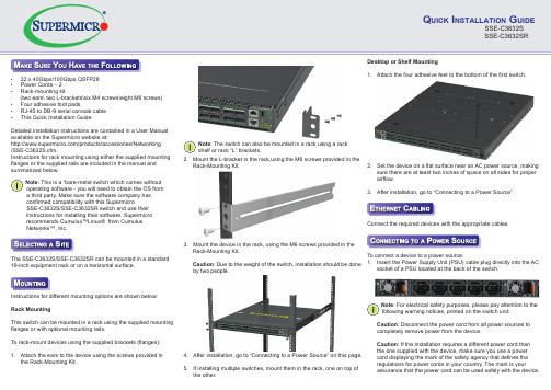
Q UICK I NSTALLATION G UIDESSE-C3632S SSE-C3632SR• 32 x 40Gbps/100Gbps QSFP28 • Power Cords – 2• Rack-mounting kit(two ears\ two L-brackets\six M4 screws\eight M6 screws)• Four adhesive foot pads• RJ-45 to DB-9 serial console cable • This Quick Installation GuideDetailed installation instructions are contained in a User Manual available on the Supermicro website at:/products/accessories/Networking /SSE-C3632S.cfm.Instructions for rack mounting using either the supplied mounting flanges or the supplied rails are included in the manual and summarized below.The SSE-C3632S/SSE-C3632SR can be mounted in a standard 19-inch equipment rack or on a horizontal surface.2. Mount the L-bracket in the rack,using the M6 screws provided in theRack-Mounting Kit.3. Mount the device in the rack, using the M6 screws provided in the Rack-Mounting Kit.Caution : Due to the weight of the switch, installation should be done by two people.4. After installation, go to “Connecting to a Power Source” on this page.5. If installing multiple switches, mount them in the rack, one on top of the other.Desktop or Shelf Mounting1. Attach the four adhesive feet to the bottom of the first switch.2. Set the device on a flat surface near an AC power source, making sure there are at least two inches of space on all sides for properairflow.3. After installation, go to “Connecting to a Power Source”.Note : For electrical safety purposes, please pay attention to the following warning notices, printed on the switch unit: Caution : Disconnect the power cord from all power sources tocompletely remove power from the device.Caution : If the installation requires a different power cord thanthe one supplied with the device, make sure you use a powercord displaying the mark of the safety agency that defines theregulations for power cords in your country. The mark is yourassurance that the power cord can be used safely with the device.Instructions for different mounting options are shown below:Rack MountingThis switch can be mounted in a rack using the supplied mountingflanges or with optional mounting rails.To rack-mount devices using the supplied brackets (flanges):1. Attach the ears to the device using the screws provided in the Rack-Mounting Kit.Connect the required devices with the appropriate cables.To connect a device to a power source:1. Insert the Power Supply Unit (PSU) cable plug directly into the ACsocket of a PSU located at the back of the switch. Note : The switch can also be mounted in a rack using a rack shelf or rack “L” brackets.Note : This is a “bare-metal switch which comes without operating software - you will need to obtain the OS from a third party. Make sure the software company has confirmed compatibility with this SupermicroSSE-C3632S/SSE-C3632SR switch and use their instructions for installing their software. Supermicro recommends Cumulus™Linux® from Cumulus Networks™, Inc.• The socket outlet must be near to the unit and easily accessible. You can only remove power from the unit by disconnecting the power cord from the outlet.• This unit operates under SELV (Safety Extra Low Voltage) conditions according to IEC 60950. The conditions are onlymaintained if the equipment to which it is connected also operates under SELV conditions.Caution : • Fiber Optic Port Safety. When using a fiber optic port, never look at the transmit laser while it is powered on. Also, never look directly at the fiber TX port and fiber cable ends when they are powered on.• This product does not contain any serviceable user parts.• Installation and removal of the unit must be carried out by qualified personnel only.• When connecting this device to a power outlet, connect the field ground lead on the tri-pole power plug to a valid earth ground line to prevent electrical hazards.• This switch uses lasers to transmit signals over fiber optic cable. The lasers are compliant with the requirements of a Class 1 Laser Product and are inherently eye safe in normal operation. However, you should never look directly at a transmit port when it is powered on.• Wear an anti-static wrist strap or take other suitable measures to prevent electrostatic discharge when handling this equipment.• Do not plug a phone jack connector in the RJ-45 port. This may damage this device.• Use only twisted-pair cables with RJ-45 connectors that conform to FCC standards. For more information and safety instruction go to:/manuals/network/Layer_2-3_SDN_Switches.pdfWeight : Net weight: 10.18kg (with 2 PSUs)LEDs:System Fan SFP+ Port 1: Status (Link/Activity)QSFP28 Ports 1~32: Status (Link/Activity)RJ-45 Port: Status (Link/Activity)Size: (W x D x H): 433.8 x 520 x 44 mm (17.07 x 20.47 x 1.73 inches)Temperature : Operating 0°C to 45 °C (32°F to 113°F)Humidity : Operating: 5% to 95% (non-condensing)AC Input : 100-127/200-240 V, 50/60 HzPower Supply:100-127/200-240 VAC, 50/60 Hz,F2B 800W @ 12V/65 A per module (For SSE-C3632S)100-127/200-240 VAC, 50/60 Hz,B2F 800W @ 12V/65 A per module (For SSE-C3632SR)Power Consumption : <650 WattsCE Mark : EN 55022 Class A, EN 55024: 2010, EN 61000-3-2 Class A,EN 61000-3-3.Immunity: EN 55024:2010, IEC 61000-4-2/3/4/5/6/8/11EMI (Class A) : FCC/VCCI/BSMISafety: UL (CSA 22.2 No 60950-1 & UL60950-1)/CB (IEC/EN60950-1)Caution : • Installation and removal of the unit must be carried out by qualified personnel only.• The unit must be connected to an earthed (grounded) outlet to comply with international safety standards.• Do not connect the unit to an A.C. outlet (power supply) without an earth (ground) connection.• The appliance coupler (the connector to the unit and not the wall plug) must have a configuration for mating with an EN 60320/ IEC 320 appliance inlet.CLASS 1LASER DEVICE 2. Plug the other end of the cable into a grounded, 3-pin, AC power source.Note : For use outside North America, you may need to change the AC line cord. You must use a line cord that has been approved for the connector type in your country. 3. Repeat steps 1 and 2 when a second PSU module is installed.Two installed PSU modules operate in a load-sharing mode andprovide 1+1 redundancy.To set up your management connection, the following parameters should be observed:• Console Interface – make sure your console settings are115200-N-8-1 (baud rate 115,200 bps).Ports:32 40Gbps/100Gbps QSFP28 transceiver slots 1 10Gbps SFP+ transceiver slotsNetwork Interface:Ports 1~32: 40Gbps/100Gbps QSFP28 Optical Transceivers:100GBASE-SR4,100GBASE-PSM4QSFP28 Direct Attach Cables can also be used in ports 1~32RJ-45 Port: RJ-45 connector, auto MDI/X 10BASE-T: RJ-45(100-ohm, UTP cable; Category 3 or better) 100BASE-TX: RJ-45(100-ohm, UTP cable; Category 5 or better) 1000BASE-T:RJ-45 (100-ohm, UTP or STP cable; Category 5, 5e or 6)*Maximum Cable Length - 100 m (328 ft)List of Transceivers and Cables :SSE-C3632SSSE-C3632SR E072014-AP-R01150200000828ATransceivers/Cables Vendor Vendor PN100GBASE-SR4Avago AFBR-89CDDZ Finisar FTLC9551REPM TL Luxtera LUX42604Molex1002971101100GBASE-SR4 100GBASE-PSM4100G DAC 1M 30AWG。
云箭 s31161ir存储服务器 用户手册说明书

S31161iR存储服务器用户手册V1.0湖南云箭智能科技有限公司目录1致尊敬的用户 (1)2声明 (2)3注意事项 (3)4开箱检查 (4)4.1随机配件 (4)4.2确认配置 (4)5产品基本说明 (5)5.1设备开关板按钮 (6)5.2设备前视图 (7)5.3设备后视图 (7)6机架安装 (7)6.1注意事项 (7)6.2滑轨的安装方法 (8)6.3产品资料索取 (10)7安装操作系统 (10)7.1注意事项 (10)7.2设置BIOS启动顺序 (11)7.3Windows Server 2012 系统的安装 (11)7.4Linux 操作系统和驱动程序安装 (16)8常见故障及注意事项 (24)9产品有害物质含量状态说明 (26)1致尊敬的用户衷心感谢您选用本公司的产品!本手册将向您介绍产品在使用中对使用环境的要求、安装指导、硬件操作、网络配置等基础使用知识,有助于您更详细的了解和使用此产品。
请将产品的包装物进行收集并交废品收购站回收利用,造福人类。
湖南云箭智能科技有限公司拥有本手册的版权。
本手册中的内容如有变动恕不另行通知。
如果您对本手册有疑问或建议请联系本公司。
服务热线:400-998-0966服务邮箱:***********************湖南云箭智能科技有限公司2020 年12月2声明在正式使用本产品之前,请先阅读以下声明:只有您阅读了以下声明并且同意以下条款后,方可正式开始使用本产品。
如果您对以下条款有任何疑问,请您和您的供货商联系或直接与我们联系。
如您未向我们就以下条款提出疑问并开始使用本产品,则是默认您已经同意了以下的条款。
1.我们提醒用户特别注意:在任何时候,除了我们提示您可以修改的参数以外,您不要修改本产品任何其它参数。
2.在您使用的本产品出现任何硬件故障时,或您希望对硬件进行任何升级时,请您将本产品的产品序列号提供给我们的技术服务中心,请您不要自行拆卸机箱或在机箱内加装不兼容的硬件设备,以免损坏本产品。
赫斯曼交换机型号说明
赫思曼(hirschmann、赫斯曼)RS20系列交换机:·可提供4个、8个、9个、16个和24个10/100Mbps端口。
·多种软件版本可供选择:非网管型(U)、网管基础版(B)、网管增强版(E)以及网管专业版(P)。
·光纤端口为多模或单模形式。
···0℃至·、全电口RS20-0800T1T1SDAEHC????????(8×RJ45,0℃至+60℃标准温度,网管增强型)RS20-0800T1T1SDAPHC????????(8×RJ45,0℃至+60℃标准温度,网管专业版)RS20-1600T1T1SDAEHC????????(16×RJ45,0℃至+60℃标准温度,网管增强型)RS20-1600T1T1SDAPHC????????(16×RJ45,0℃至+60℃标准温度,网管专业版)RS20-2400T1T1SDAEHC????????(24×RJ45,0℃至+60℃标准温度,网管增强型)RS20-2400T1T1SDAPHC????????(24×RJ45,0℃至+60℃标准温度,网管专业版)多模光纤RS20-0400M2T1SDAEHC????????(3×RJ451×SC,0℃至+60℃标准温度,网管增强型)RS20-0400M2T1SDAPHC????????(3×RJ451×SC,0℃至+60℃标准温度,网管专业版)RS20-0400M2M2SDAEHC????????(2×RJ452×SC,0℃至+60℃标准温度,网管增强型)RS20-0400M2M2SDAPHC????????(2×RJ452×SC,0℃至+60℃标准温度,网管专业版)RS20-0800M2M2SDAEHC????????(6×RJ452×SC,0℃至+60℃标准温度,网管增强型)RS20-0400S2S2SDAPHC????????(2×RJ452×SC,0℃至+60℃标准温度,网管专业版)RS20-0800S2S2SDAEHC????????(6×RJ452×SC,0℃至+60℃标准温度,网管增强型)RS20-0800S2S2SDAPHC????????(6×RJ452×SC,0℃至+60℃标准温度,网管专业版)RS20-1600S2S2SDAEHC????????(14×RJ452×SC,0℃至+60℃标准温度,网管增强型)RS20-1600S2S2SDAPHC????????(14×RJ452×SC,0℃至+60℃标准温度,网管专业版)RS20-2400S2S2SDAEHC????????(22×RJ452×SC,0℃至+60℃标准温度,网管增强型)RS20-2400S2S2SDAPHC????????(22×RJ452×SC,0℃至+60℃标准温度,网管专业版)赫思曼(hirschmann、赫斯曼)MS4128-L2P系列交换机:·4个100Mbps插槽形式。
国家信息安全产品认证获证名单
第一级
网御 SIS-3000 安全隔离与信息交换系统 V1.0(千兆) 第二级
网康互联网控制网关 NS-ICG/V5.5.1(安全审计产品) 基本级
数字电视条件接收系统智能卡软件(V5.1)
EAL4 增 强级
绿盟安全审计系统 V5.6
增强级
绿盟网络入侵检测系统 V5.6?(百兆)
第三级
绿盟安全网关 V5.6(百兆)(防火墙产品)
证书 状态 有效 有效 有效 有效 有效 有效 有效 有效 有效 有效
精心整理
序 证书号
号
11
12
13
200
14 15 16 17 18 19
20
21 22 23 24
25
26
27
20
产品名称及型号/版本 捷普入侵检测系统 JIDS-N1000/V3.0(千兆)
捷普信息审计系统 JBCA/V3.0
捷普主机监控与审计系统 JHAUDIT/V2.0 SecowayUSG2000?防火墙 V3.3(百兆) SecowayUSG5000?防火墙 V3.3(千兆) QuidwayEudemon200E 防火墙 V3.3(百兆) QuidwayEudemon1000E 防火墙 V3.3(千兆) 华堂千兆网络安全防御系统 V4.3(防火墙产品) 华堂网络安全防御系统 V4.0(防火墙产品)(百兆)
有限公司 北京天融信 科技有限公
司 北京天融信 科技有限公
司 北京网御星 云信息技术
有限公司 杭州迪普科 技有限公司 北京网御星 云信息技术
有限公司 北京网御星 云信息技术
有限公司
发证时间 2009-12-10 2009-12-22 2009-12-24 2009-12-24 2009-12-24
LTtray规格书

LTtray规格书產品規格以實際出貨為準,任何疑問請洽傳易科技全省分公司產品概述:SMC6726L3提供無阻斷的線速 (wire-speed) 傳送速率可達8.8 Gbps ,可讓企業網路得到最佳的效能,並提供許多功能讓企業享有絕佳的網路安全與穩定性,支援第三層路由功能RIP/RIPII 、OSPF 還包括VLAN (GVRP)、 IGMP。
Snooping 、QoS/COS 、支援RADIUS 、802.1x 、SSH 、SSLTACACS+、ACL等功能。
產品規格硬體介面:24個 10/100 Base-TX 埠,支援自動調速與自動跳線偵測功能。
支援MiniGBIC 1000Base-SX 、1000Base-LX 與1000Base-Zx可輕鬆擴充網路頻寬。
符合標準:IEEE 802.3 10Base-T 乙太網路IEEE 802.3u 100Base-Tx 乙太網路IEEE 802.ab 1000Base-T 乙太網路IEEE 802.1d Spanning Tree 協定IEEE 802.1w Rapid Spanning Tree 協定IEEE 802.3ad Port aggregation 協定IEEE802.1p服務等級區隔優先程度協定IEEE802.1x效能8.8Gbps 非阻塞式交換結構(non-blocking switching fabric)。
功能支援8,000(含)以上之MAC Addresses 。
支援大型封包(Jumbo Frame)最高可支援9216 byte 。
每一埠都支援廣播流量控制以避免廣播風暴產生。
每一埠都支援802.1x安全認證功能。
最高可支援到255組IEEE 802.1q標準VLAN Group 。
支援IEEE 802.1d Spanning Tree及802.1w Rapid Spanning Tree(RSTP)。
支援第三層路由功能RIPV1/V2、OSPF。
Moxa MB3660系列1至16端口冗余Modbus网关产品说明书
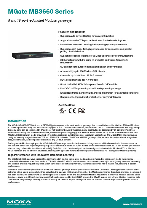
MGate MB3660Series8and16-port redundant Modbus gatewaysFeatures and Benefits•Supports Auto Device Routing for easy configuration•Supports route by TCP port or IP address for flexible deployment•Innovative Command Learning for improving system performance•Supports agent mode for high performance through active and parallelpolling of serial devices•Supports Modbus serial master to Modbus serial slave communications•2Ethernet ports with the same IP or dual IP addresses for networkredundancy•SD card for configuration backup/duplication and event logs•Accessed by up to256Modbus TCP clients•Connects up to Modbus128TCP servers•RJ45serial interface(for“-J”models)•Serial port with2kV isolation protection(for“-I”models)•Dual VDC or VAC power inputs with wide power input range•Embedded traffic monitoring/diagnostic information for easy troubleshooting•Status monitoring and fault protection for easy maintenanceCertificationsIntroductionThe MGate MB3660(MB3660-8and MB3660-16)gateways are redundant Modbus gateways that convert between the Modbus TCP and Modbus RTU/ASCII protocols.They can be accessed by up to256TCP master/client devices,or connect to128TCP slave/server devices.Routing through the serial ports can be controlled by IP address,TCP port number,or ID mapping.Serial-port routing by designated TCP port and IP address allows access for up to4TCP clients/masters,while routing by ID mapping(slave ID table)allows access for up to256TCP clients/masters.The MGate MB3660isolation model provides2-kV isolation protection suitable for power substation applications.The MGate MB3660gateways are designed to easily integrate Modbus TCP and RTU/ASCII networks.The MGate MB3660gateways offer features that make network integration easy,customizable,and compatible with almost any Modbus network.For large-scale Modbus deployments,MGate MB3660gateways can effectively connect a large number of Modbus nodes to the same network. The MB3660Series can physically manage up to248serial slave nodes for8-port models or496serial slave nodes for16-port models(the Modbus standard only defines Modbus IDs from1to247).Each RS-232/422/485serial port can be configured individually for Modbus RTU or Modbus ASCII operation and for different baudrates,allowing both types of networks to be integrated with Modbus TCP through one Modbus gateway. High Performance with Innovative Command LearningThe MGate MB3660gateways support two communication modes:transparent mode and agent mode.For transparent mode,the gateway converts Modbus commands from Modbus TCP to Modbus RTU/ASCII,and vice versa,or from serial(master)to serial(slave).However,since only one Modbus protocol request-response action can be executed at any given time,each Modbus device has to wait its turn,resulting in poorer performance.In order to provide better performance,the MGate MB3660gateways are designed with an innovative Command Learning function,which can be activated with a single mouse click.Once activated,the gateway will learn and remember the Modbus commands it receives,and once a command has been learned,the gateway will act as though it were in agent mode,and actively send Modbus requests to the relevant Modbus devices.Since the data is saved in a different memory space that can be accessed by the SCADA system,the SCADA system can retrieve Modbus response data directly from the gateway’s memory,instead of waiting for the data to pass through the Modbus devices,dramatically increasing communication performance.Auto-Device Routing for Easy ConfigurationMoxa’s Auto-Device Routing function helps eliminate many of the problems and inconveniences encountered by engineers who need to configure large numbers of Modbus devices.A single mouse click is all that’s required to set up a slave ID routing table and configure Modbus gateways to automatically detect Modbus requests from a supervisory control and data acquisition(SCADA)system.By removing the need to manually create the slave ID routing table,the Auto-Device Routing function saves engineers significant time and reduces cost.Modbus Gateway with Power and Ethernet RedundancyFor a complicated Modbus system,redundancy is extremely important.The MGate MB3660Modbus gateways support redundancy for both the power input and Ethernet connection.The MGate MB3660gateways come with dual AC or DC power inputs built in for power redundancy,and have dual Ethernet ports(with different IPs)for network redundancy.To accommodate different types of applications,the dual Ethernet ports can be configured in one of two ways:•Use the same IP for both Ethernet ports.In this case,the MGate MB3660gateway will automatically switch to the backup LAN when the main LAN fails.•Use different IP addresses for each of the two Ethernet ports.In this case,Modbus clients/masters can use both Ethernet ports to communicate with Modbus RTU/ASCII slave devices at the same time.SpecificationsEthernet Interface10/100BaseT(X)Ports(RJ45connector)2IP addressesAuto MDI/MDI-X connectionEthernet Software FeaturesIndustrial Protocols Modbus TCP Client(Master)Modbus TCP Server(Slave)Configuration Options Web Console(HTTP/HTTPS)Device Search Utility(DSU)MCC ToolTelnet ConsoleManagement ARPDHCP ClientDNSHTTPHTTPSSMTPSNMP TrapSNMPv1/v2c/v3TCP/IPTelnetUDPNTP ClientRADIUSMIB RFC1213,RFC1317Time Management NTP ClientSecurity FunctionsAuthentication Local databaseRADIUSEncryption HTTPSAES-128AES-256SHA-256Security Protocols SNMPv3HTTPS(TLS1.2)Serial InterfaceNo.of Ports MGate MB3660-8Series:8MGate MB3660-16Series:16Connector MGate MB3660-8/16:DB9maleMGate MB3660-8/16-J:RJ45Serial Standards RS-232/422/485(software selectable)Baudrate50bps to921.6kbpsData Bits7,8Stop Bits1,2Parity NoneEvenOddSpaceMarkFlow Control RTS/CTSDTR/DSRRTS Toggle(RS-232only)Console Port RS-232(TxD,RxD,GND),8-pin RJ45(115200,n,8,1) Isolation2kV(I models)RS-485Data Direction Control ADDC(automatic data direction control)Pull High/Low Resistor for RS-4851kilo-ohm,150kilo-ohmsTerminator for RS-485120ohmsSerial SignalsRS-232TxD,RxD,RTS,CTS,DTR,DSR,DCD,GNDRS-422Tx+,Tx-,Rx+,Rx-,GNDRS-485-2w Data+,Data-,GNDRS-485-4w Tx+,Tx-,Rx+,Rx-,GNDSerial Software FeaturesIndustrial Protocols Modbus RTU/ASCII MasterModbus RTU/ASCII SlaveConfiguration Options Serial ConsoleModbus RTU/ASCIIMode Master,SlaveFunctions Supported1,2,3,4,5,6,15,16,23Max.No.of Commands256per serial portMemory Size65535bytesModbus TCPMode Client(Master),Server(Slave)Max.No.of Client Connections256Max.No.of Server Connections128Functions Supported1,2,3,4,5,6,15,16,23Max.No.of Commands256Memory Size65535bytesModbus(Transparent)Max.No.of Client Connections256Max.No.of Server Connections128Power ParametersInput Voltage All models:Redundant dual inputsAC models:100to240VAC(50/60Hz)DC models:20to60VDC(1.5kV isolation)No.of Power Inputs2Power Connector Terminal block(for DC models)Power Consumption MGate MB3660-8-2AC:109mA@110VACMGate MB3660I-8-2AC:310mA@110VACMGate MB3660-8-J-2AC:235mA@110VACMGate MB3660-8-2DC:312mA@24VDCMGate MB3660-16-2AC:141mA@110VACMGate MB3660I-16-2AC:310mA@110VACMGate MB3660-16-J-2AC:235mA@110VACMGate MB3660-16-2DC:494mA@24VDCRelaysContact Current Rating Resistive load:2A@30VDCPhysical CharacteristicsHousing MetalIP Rating IP30Dimensions(with ears)480x45x198mm(18.90x1.77x7.80in)Dimensions(without ears)440x45x198mm(17.32x1.77x7.80in)Weight MGate MB3660-8-2AC:2731g(6.02lb)MGate MB3660-8-2DC:2684g(5.92lb)MGate MB3660-8-J-2AC:2600g(5.73lb)MGate MB3660-16-2AC:2830g(6.24lb)MGate MB3660-16-2DC:2780g(6.13lb)MGate MB3660-16-J-2AC:2670g(5.89lb)MGate MB3660I-8-2AC:2753g(6.07lb)MGate MB3660I-16-2AC:2820g(6.22lb)Environmental LimitsOperating Temperature0to60°C(32to140°F)Storage Temperature(package included)-40to85°C(-40to185°F)Ambient Relative Humidity5to95%(non-condensing)Standards and CertificationsEMC EN55032/35EMI CISPR32,FCC Part15B Class AEMS IEC61000-4-2ESD:Contact:6kV;Air:8kVIEC61000-4-3RS:80MHz to1GHz:10V/mIEC61000-4-4EFT:Power:1kV;Signal:1kVIEC61000-4-5Surge:Power:2kV;Signal:1kVIEC61000-4-6CS:10VIEC61000-4-8PFMFSafety MGate MB3660-8-2AC/16-2AC/8-2DC/16-2DC:IEC62368-1,UL62368-1MGate MB3660I-8-2AC/16-2AC:IEC62368-1,UL62368-1MGate MB3660-8-J-2AC/16-J-2AC:UL60950-1Freefall IEC60068-2-31Shock IEC60068-2-27Vibration IEC60068-2-6IEC60068-2-64MTBFTime MGate MB3660-8-2AC:721,988hrsMGate MB3660-8-2DC:711,978hrsMGate MB3660-8-J-2AC:616,505hrsMGate MB3660-16-2AC:495,416hrsMGate MB3660-16-2DC:490,684hrsMGate MB3660-16-J-2AC:437,337hrsMGate MB3660I-8-2AC:429,807hrsMGate MB3660I-16-2AC:256,208hrs Standards Telcordia SR332WarrantyWarranty Period5yearsDetails See /warranty Package ContentsDevice1x MGate MB3660Series gateway Power Supply1x power cord,suitable for your region Cable1x RJ45-to-DB9console cable Installation Kit1x wall-mounting kitDocumentation1x quick installation guide1x warranty cardDimensionsOrdering InformationModel Name No.of Serial Ports Serial Connector Serial Isolation Input Voltage MGate MB3660-8-2DC8DB9male–20-60VDC(1.5kV isolation) MGate MB3660-16-2DC16DB9male–20-60VDC(1.5kV isolation) MGate MB3660-8-2AC8DB9male–100-240VAC(47-63Hz) MGate MB3660-16-2AC16DB9male–100-240VAC(47-63Hz) MGate MB3660I-8-2AC8DB9male2kV100-240VAC(47-63Hz)MGate MB3660I-16-2AC16DB9male2kV100-240VAC(47-63Hz) MGate MB3660-8-J-2AC8RJ45–100-240VAC(47-63Hz) MGate MB3660-16-J-2AC16RJ45–100-240VAC(47-63Hz) Accessories(sold separately)CablesCBL-F9M9-150DB9female to DB9male serial cable,1.5mCBL-F9M9-20DB9female to DB9male serial cable,20cmCBL-RJ45F9-1508-pin RJ45to DB9female serial cable,1.5mCBL-RJ45SF9-1508-pin RJ45to DB9female serial cable with shielding,1.5mConnectorsMini DB9F-to-TB DB9female to terminal block connectorPower CordsPWC-C13AU-3B-183Power cord with Australian(AU)plug,1.83mPWC-C13CN-3B-183Power cord with three-prong China(CN)plug,1.83mPWC-C13EU-3B-183Power cord with Continental Europe(EU)plug,1.83mPWC-C13JP-3B-183Power cord with Japan(JP)plug,7A/125V,1.83mPWC-C13UK-3B-183Power cord with United Kingdom(UK)plug,1.83mPWC-C13US-3B-183Power cord with United States(US)plug,1.83mCBL-PJTB-10Non-locking barrel plug to bare-wire cableMounting KitsWK-45-01Wall-mounting kit,2L-shaped plates,6screws,45x57x2.5mm©Moxa Inc.All rights reserved.Updated Aug07,2023.This document and any portion thereof may not be reproduced or used in any manner whatsoever without the express written permission of Moxa Inc.Product specifications subject to change without notice.Visit our website for the most up-to-date product information.。
- 1、下载文档前请自行甄别文档内容的完整性,平台不提供额外的编辑、内容补充、找答案等附加服务。
- 2、"仅部分预览"的文档,不可在线预览部分如存在完整性等问题,可反馈申请退款(可完整预览的文档不适用该条件!)。
- 3、如文档侵犯您的权益,请联系客服反馈,我们会尽快为您处理(人工客服工作时间:9:00-18:30)。
YA7121-0/2Local Motion Control BoardNippon Pulse Motor Co., Ltd. RRemoteI/O & RemoteMotion目录1. 前言 (1)2. 功能 (3)21. 串行通讯 (3)22. 运动控制 (5)3. 预防与安全 (8)31. 安全注意事项 (8)32. 操作注意事项 (8)4. 保修期及范围 (8)5. 规格 (9)51. 串行通讯 (9)52. 运动控制 (10)53. 其它 (11)6. 结构 (12)7. 连接器引脚分配 (13)71. CN1, 2 (串行通讯接口) (13)72. CN3 (机械输入/输出,电源连接器) (13)73. CN4 (伺服驱动器连接器) (14)74. 连接器使用 (14)8. 信号和功能 (16)81. 命令脉冲输出(PULSP, PULSN, DIRP, DIRN) (16)82. 编码器输入(EAP, EAN, EBP, EBN, EZP, EZN) (18)83. 驱动器系统输入 (ALM, INP, SVRDY, PNA) (20)84. 驱动器系统输出(ERC, SVON, ALMRES, TL, ZST) (22)85. 机械输入/输出(PEL, MEL, SD/CPP, ORG, EMGI, CPN) 及伺服驱动器输出(EMGO) (25)86. 串行通讯(RS485+, RS485) (29)87. 电源 (24V, GND, FG) (29)9. 串行通讯 (30)91. 通讯协议 (30)92. 通讯配置 (30)93. 数据通讯时间 (31)10. 拨码开关设置 (32)101. 串行通讯设备号设置(SW1ADDRESS A0 to A5) (32)102. 设置传输速度 (SW1L. SPEED B0, B1) (32)103. 设置结束极限逻辑(SW1EL) (32)104. 设置终端电阻 (SW1TR) (32)105. 选择降速输入或比较器(+)输出(SEL) (33)11. 状态展示 (33)111. 通讯状态展示LED (RUN) (33)112. 通讯状态展示LED (ERR) (33)113. 电源指示LED (POWER) (33)114. 机械输入状态展示(PEL, MEL, SD, ORG, EMG) (33)12. 串行通讯线缆 (34)13. 连接器及拨码开关布局 (35)14. 设置G9003 寄存器及伺服驱动器用户常量 (36)141. G9003 环境设置 1 (RENV1) (36)142. G9003环境设置2 (RENV2) (36)143. 通用输入/输出端分配及状态 (37)144. 伺服驱动器用户常量设置 (37)15. 外部尺寸 (41)16. 附录 (42)1. 前言感谢您购买我们的单轴运动控制卡。
该卡为本地高速串行通讯卡,使用的通讯协议为Motionnet 。
您所购买的MNETM361VPS 为单轴运动控制板卡,其中包含了我们Motionnet G9003 PLC 。
该板产品的CN4可 直接到Nikki Denso 的VPS 系列伺服驱动器的CN1上,当接收到伺服的I/O 信号时,即可控制伺服电机。
该板卡 可持续进行速度模式(恒定的速度,直线加速/减速,S 曲线加速/减速,以及预设置位操作,并返回一个零操作)控 制,并通过各种串行通信,使的伺服电机不间断运行。
由于此板可直接连接到伺服的I/O 信号,它不需要传统用于连接运动控制板卡的特殊伺服驱动器电缆。
因此,该板 卡将节省许多人为的设计和布线系统的时间。
此外,它还带来不少优势:比如简化布线,缩短线路运行,故它消除 了线路故障引起的问题。
它还提供高抗干扰,并可充分利用高速信号线路处理命令脉冲。
该板卡设计紧凑,不需要 任何额外的空间布线。
该板卡由中心主板上的Motionnet 核心控制器G9001A 进行控制。
此外,该板卡通过了RoHS 标准认识,利于环保□Motionnet 是来自NPM (Nippon Pulse Motor )创建的超高速串行通信系统。
使用NPM 提供的四个专门开发的核心芯片设备(G9001A ,G9002,G9003 和G9004),可以构建该串行通信系 统。
该系统是一种通过仿真CPU 和CPU 的信息处理建成完整体系的输入操作和输出操作的通信系统,在减少布线 的情况下最高可以达到20 Mbps 的传输速度。
它所有的高速I/O 的输入、输出完全由运动控制提供。
设备G9001A: 核心设备这是一个来管理本地设备的中央控制器。
此设备有256字节的RAM 用于I/O 控制, 512字节的RAM 用于数据 通信。
这个设备可以让远程操作就像CPU 的内存访问。
它可以最大连接64个G9002,G9003或者G9004。
G9002: IO 设备这是一个本地I / O 控制设备,可以控制32个独立的I / O 信号。
G9003: PCL 设备这是一个本地设备,包含有脉冲控制器LSI ,其中LSI 为NPM 自主研发多年的用于电机控制的控制器。
它可 以控制单脉冲输入型步进电机和伺服电机。
G9004:CPU 仿真设备这是最先进的Motionnet 系列的本地设备,它连接到一个CPU (例如NPM 的PCL6045B )就可以进行远程控 制。
通过连接一个CPU 的端口,它也可以在CPU 之间的传递消息。
远程I/O如果Motionnet总线只对输入和输出控制,它可以在64个本地设备上用0.97ms 的时间发送和接收2048点的信 号数据(使用20 Mbps 的数据传输速度)。
(如果数量较少的设备连接,数据传输的时间会更短。
)R远程运动控制如果Motionnet线仅用于控制马达,它可以控制多达64个轴。
这种类型的控制,单个设备可以控制脉冲输入式步 进电机和伺服电机。
他们可以执行恒定速度持续运行,直线加速/减速,和S曲线加速/减速,以及进行预设置位 和归零操作。
一个系统上连接两种类型的电机也是可能的.和连接设备的数量以及数据传输速度选择相关,使用普通双绞线CAT5 LAN电缆,系统长度可以延长到100米。
串行通信是一个接收响应类型的协议。
该协议增加了通信帧检测错误,从而提供更高的可靠性。
您关于通信的准 确性是不用担忧了。
□该用户说明手册着重描述MNETM361VPS规格及使用方法。
我们希望您可以通读全文并能完全吸收该板卡的 各种功能。
这部分用户手册暂无G9001A及G9003LS系列的功能描述。
更多关于函数及寄存器的详情,请参考"Motionnet RemoteI/O RemoteMotion G9001A/G9002 (Center device /I/O device) User's Manual" 及 "Motionnet G9003 (PCL device) User's Manual".2. 功能该板卡的功能可分为串行通讯及运动控制两个方面。
21. 串行通讯数据传输速度最大值 20Mbps循环通讯时间及传输周期通讯环周期最大 15.1µs/unit (数据传输速率: 20 Mbps)数据传输周期当连接64个本地设备,最大可达0.97 ms (数据传输速率20Mbps)(当连接少量设备时,传输速率将成比例加快)数据通讯时间最大 19.3 µs (当写入4字节到G9003设置的寄存器)可支持设备数量每线最多可支持 64 设备连接方法Motionnet上多点电缆连接。
串行通讯类型可支持三种通讯类型1) 系统通讯对Motionnet线路进行轮询,获得已连接的本地设备数量及类型,并且检测分配的I/O端口状态。
2) 环状通讯该系统开始与本地具有最低设备号的设备通讯。
当通信周期找到最高设备号的设备时,系统重新启动,并且 与最低设备号的设备通讯。
与所有已激活设备通讯的过程中,从最低设备号到最高设备号为一周期。
该系统 自动重复这个过程。
主要关键条件(如脉冲输出状态)获取及在G9003上的通用I/O数据也可在该通讯环中处理。
3) 数据通讯该通讯类型用于处理PCL设备及CPU仿真设备之间的数据。
当数据写入核心设备的FIFO,该通讯将自动被环状通讯中断发送的接收。
数据通讯也常常用于向G9003的寄存器写入操作指令。
通讯错误检测错误可由加入到串行通讯的CRC代码检测到。
22. 运动控制中断信号输出中断请求可由各种原因发送到中心板卡。
加速/减速控制直线及S型曲线加速/减速均可使用。
其中在S型曲线的加速/减速中可调用部分直线加速/减速应用。
速率变更在全模式中,速度可由任何操作进行改变。
目标位置变更在使用位置模式功能中,目标位置可发生改变。
当供给控制已经通过了新的目标位置,电机将会减速并停止(当执行匀速运动时将会立刻停止),并开始给送相反 的方向。
抑制三角波(FH校正)当在位置模式中,如果仅有少量输出脉冲,板卡将自动降低最高速度来避免三角波的发生。
超大计数器电路允许三种计数器计数器 目 的 计数输入 COUNTER1 28位计数器控制命令指令位置 输出脉冲COUNTER2 28位计数器控制机械位置(可作为通讯计数器) 输出脉冲 EA/EB 输入COUNTER3 16位计数器控制于除指令位置及机械位置之外的位置。
或 为16位通用计数器并伴随有同步信号输出功能。
输出脉冲EA/EB 输入1/4096 的相对时钟输出脉冲及EA/EB 输入可通过向设备写入指令来重置所以计数器可能过向设备写入指令或输入ORG信号来锁存计数器数据比较器板卡上有三个比较器电路,可用于比较当前值与内部计数器值。
COUNTER 1 (指令位置计数器)COUNTER 2 (机械位置计数器)COUNTER 3 (通用,偏转计数器)可用于指定计数器进行比较 比较器1和2也可来作软件极限设备 (+SL,SL).软件极限功能可设置软件极限,其中软件极限将使用两个比较器当给达位置进入软件极限位置时,电机将立刻停止或减速并停止。