1_System Components_New
科尔摩根伺服说明书

CD S YNQ N ETQ UICK S TART G UIDERevision No: 7Date: 22 December 20041. General1.1 Safety InformationOnly qualified personnel are permitted to transport, assembly, commission, and maintenance this equipment. Properly qualified personnel are persons who are familiar with the transport, assembly, installation, commissioning and operation of motors, and who have the appropriate qualifications for their jobs. The qualified personnel must know and observe the following standards and regulations:IEC 364 resp. CENELEC HD 384 or DIN VDE 0100 IEC report 664 or DIN VDE 0110National regulations for safety and accident prevention or VBG 4 •Read all available documentation before assembly and commissioning. Incorrect handling of products in this manual can result in injury and damage to persons and machinery. Strictly adhere to the technical information on the installation requirements.• It is vital to ensure that all system components are connected to earth ground. Electrical safety is impossible without a low-resistance earth connection.•The SERVOSTAR® product contains electro-statically sensitive components that can be damaged by incorrect handling. Discharge any electrical shock potential from you before touching the product. Avoid contact with high insulating materials (artificial fabrics, plastic film, etc.). Place the product on a conductive surface.• During operation keep all covers and cabinet doors shut. Otherwise, there are deadly hazards that could possibility cause severe damage to health or the product.• In operation, depending on the degree of enclosure protection, the product can have bare components that are live or have hot surfaces. Control and power cables can carry a high voltage even when the motor is not rotating. • Never pull out or plug in the product while the system is live. There is a danger of electric arcing and danger to persons and contacts.•After powering down the product, wait at least ten minutes before touching live sections of the equipment or undoing connections (e.g., contacts, screwed connections). Capacitors can store dangerous voltages for long periods of time after power has been switched off. To be safe, measure the contact points with a meter before touching.When these symbols are seen in this manual, be alert to the potential for personal injury. Follow the recommended precautions and safe operating practices included with the alert symbols. Safety notices in this manual provide important information. Read and be familiar with these instructions before attempting installation, operation, or maintenance. The purpose of this section is to alert users to possible safety hazards associated with this equipment and the precautions that need to be taken to reduce the risk of personal injury and damage to the equipment. Failure to observe these precautions could result in serious bodily injury,damage to the equipment, or operational difficulty. The safety-alert symbols are:Warning Alerts users to potential physical danger or harm. Failure to follow warning notices could result in personal injury or death.Caution Directs attention to general precautions, which if not followed, could result in personal injuryand/or equipment damage.Note Highlights information critical to your understanding or use of the product.1.2 Limited WarrantyIncludes software provided by KollmorgenSeller warrants that the Goods sold hereunder are free from defects in material and workmanship for the product warranty period of each item of Goods (Product Warranty Periods are listed below). Seller warrants its Good(s) only to the originalpurchaser (the “Customer”), and in the case of original equipment manufacturers or distributors, only to their original consumer (the “Customer”). There are no warranties whatsoever on Goods built or acquired, wholly or partially, to a buyer’s designs or specificationsThis express warranty is in lieu of and exclude all other warranties, express or implied, by operation or law or otherwiseincluding THE WARRANTY OF MERCHANTABILITY AND FITNESS FOR A PARTICULAR PURPOSE (WHETHER KNOWN TO SELLER OR NOT), all other such warranties being hereby expressly disclaimed by Seller and waived by Buyer. Written notice of claimed defects shall have been given to Seller within the period set forth in the schedule below, and within thirty (30) days from the date any such defect is first discovered.广州科沃—工控维修的120 www.gzkowo.com1.2.1 Product Warranty SchedulesBrand Products Warranty Period Kollmorgen Standard Brush-type Motors,Electronics and Accessories12 months from date of manufactureKollmorgen Standard Brushless Motors, Electronicsand Accessories24 months from date of manufactureKollmorgen Standard Step Motors, Stepper Controlsand Accessories12 months from date of manufactureKollmorgen Custom Motion Systems or componentsof any type To be negotiated on a case-by-case basis, and set forth in the order.Pacific Scientific All Products 24 months from date of manufactureSuperior All Products 12 months from date of manufactureThe Goods or parts claimed to be defective must be returned to Seller, accompanied by a Return Material Authorization (RMA) issued by Seller’s facility responsible for supplying Goods, with transportation prepaid by Customer, with written specifications of the claimed defect.If a warranty claim is valid, Seller shall pay reasonable one-way costs of transportation of the defective Goods from either the original destination or the location where defect occurred, whichever is closest to Seller’s facility. Under no circumstances shall Seller be liable for removal of Seller’s Goods from Buyer’s equipment or re-installation into Buyer's equipment.No person, including any agent, distributor, or representative of Seller, is authorized to make any representation or warranty on behalf of Seller concerning any goods manufactured by Seller, except to refer purchasers to this warranty.1.2.2 GeneralIndemnityBuyer agrees to hold Seller harmless from any and all liability, and to pay all costs and attorney’s fees, for injury or damage to persons or property caused in any manner by Goods covered by the order while in possession or under the control of Buyer or Buyer’s successor in interest.1.2.3 Use As DirectedThe following guidelines describe the restrictions for proper use of the SERVOSTAR CD SynqNet system: • The amplifiers are components built into electrical equipment or machines and can only be commissioned as integral components of such equipment.• The servo amplifiers are to be used only on earthed three-phase industrial mains supply networks (TN-system, TT-system with earthed neutral point).• The servo amplifiers must not be operated on power supply networks without an earth or with an asymmetrical earth.• If the servo amplifiers are used in residential areas, or in business or commercial premises, the user must implement additional filter measures.• The servo amplifiers are only intended to drive specific brushless synchronous servomotors from Kollmorgen with closed-loop control of torque, speed, and position. The rated voltage of the motors must be at least as high as theDC-link voltage of the servo amplifier.• The servo amplifiers may only be operated in a closed switchgear cabinet, taking into account the ambient conditions defined in the environmental specifications.Kollmorgen guarantees the conformance of the servo amplifiers with the standards for industrial areas stated in this manual only if Danaher Motion Kollmorgen delivers the components (motors, cables, amplifiers etc).1.2.4 SoftwareWarrantyComputer software programs that may be included in material or Goods sold to Buyer have been designed to perform a given set of tasks as defined in the documentation provided and are offered AS IS. It is Buyer’s responsibility to determine if the features of the software programs are suitable for Buyer’s requirements and must confirm that the software programs operate correctly. Buyer understands that such software programs are of such complexity that they may have inherent defects and that Seller makes no warranty that all software features will perform correctly as supplied. For Seller’s software utilizing automation servers, improper reading and writing data to the automation server can cause the automation server software to malfunction and may cause the automation server and/or the program writing to the automation server to crash. Improperly reading and writing data to an automation server may cause the device controlled by that automation server to malfunction. Seller shall not be responsible for damage to any device or damage caused by any device due to the improper reading and/or writing of data to an automation server.1.2.5 Limitation of liabilityNOTWITHSTANDING ANYTHING TO THE CONTRARY, SELLER SHALL NOT BE LIABLE FOR ANY SPECIAL, INCIDENTAL, INDIRECT OR CONSEQUENTIAL DAMAGES INCLUDING LOST PROFITS ARISING OUT OF THE PERFORMANCE, DELAYED PERFORMANCE OR BREACH OF PERFORMANCE OF THIS ORDER REGARDLESS WHETHER SUCH LIABILITY BE CLAIMED IN CONTRACT, EQUITY, TORT OR OTHERWISE. SELLER’S OBLIGATION ISLIMITED SOLELY TO REPAIRING OR REPLACING (AT ITS OPTION AND AS SET FORTH IN SECTION 10 AND SECTION 11), AT ITS APPROVED REPAIR FACILITY, ANY GOODS OR PARTS WHICH PROVE TO SELLER’S SATISFACTION TO BE DEFECTIVE AS A RESULT OF DEFECTIVE MATERIALS OR WORKMANSHIP, IN ACCORDANCE WITH SELLER’S STATED WARRANTY. IN NO EVENT SHALL SELLER’S LIABILITY EXCEED THE TOTAL PURCHASE PRICE SET FORTH IN THIS ORDER.number1.3 Part1.4 Where to get supportDanaher Motion is committed to quality customer service. Our goal is to provide the customer with information and resources as soon as they are needed. In order to serve in the most effective way, contact your local sales representative for order status and delivery information, product information and literature, and application and field technical assistance. If you are unaware of your local sales representative, please contact us at:Email: sep@Specify “SynqNet Support” in the subject line.1.5 Manual Download LocationComplete product manuals can be downloaded from the Danaher Motion website, at -> Customized Products -> Drives -> CD SynqNet2. Unpacking and InspectionOpen the box and remove all the contents. Check to ensure there is no visible damage to any of the equipment.Electronic components in this amplifier are design-hardened to reduce static sensitivity. However, properprocedures should be used when handling to avoid damage to equipment.Remove all packing material and equipment from the shipping container. Be aware that some connector kits and other equipment pieces may be quite small and can be accidentally discarded if care is notobserved when unpacking the equipment. Do not dispose of shipping materials until the packing list hasbeen checked.Upon receipt of the equipment, inspect components to ensure that no damage has occurred in shipment. If damage is detected, notify the carrier immediately. Check all shipping material for connector kits, documentation, diskettes, CD-ROM, or other small pieces of equipment.3. Installation Instructions3.1 GeneralThese installation steps are designed to lead you through the proper installation and setup of a SERVOSTAR CD SynqNetsystem. They were developed with the assumption that you have a fundamental understanding of basic electronics, computers, mechanics, and proper safety practices. However, you do not have to be an expert in motion control to install and operate thedrive system. It is recommended that you read the entire manual completely before attempting installation or operation.High voltage can present dangerous and hazardous conditions if not performed by a qualified electrician. Be certain to follow all national and local codes during installation.1. Open the box(es) and remove all the contents. Check to ensure there is no visible damage to any of the equipment.2. Mount the SERVOSTAR CD SynqNet to the back panel. Refer to the appropriate Outline Dimensions in this manual. Metal-to-metal contact is important for electrical noise control!3. Wire the SERVOSTAR CD SYNQNET according to the appropriate System Wiring Diagram.4. Connect solid earth ground to frames of all components.5. Wire the main power (115/230 VAC). Wire the 24 volt supply to the connector at the top of the drive.6. Wire user I/O at connector C3: At a minimum, 24 volts must be brought in to the enable circuit. Be certain that connector C3 is inserted correctly.7. Wire the motor and feedback. Refer to the Feedback Wiring Diagram for additional information. 8. Wire Regen Resistor kit, if applicable. 9.Verify that all wiring is correct.10. Verify that earth grounds are connected. 11. Verify all electrical and safety codes are met.12. Connect the SynqNet cable between the Motion Controller and connector C4.3.2 GroundingSystem grounding is essential for proper performance of the drive system. A ground bus bar may be used as a single point ground for the system. Safety grounding should be provided to all pieces of the system from a “star point." In addition to the safety grounding, a high frequency ground must be provided that connects the back panel to the enclosure and, ultimately, to earth ground. The objective is to provide an extremely low impedance path between the filters, drives, power supplies, and earth ground. This high frequency ground is accomplished with the use of a flat braid or copper bus bar. It is important not to rely on a standard wire for the high frequency ground. In general, a wire has an inductance of 8nH-per-inch, regardless of diameter. At higher frequencies, this unwanted inductance between grounds equates to limited filter performance. When connecting high frequency grounds, use the shortest braid possible.3.3 BondingThe proper bonding of shielded cables is imperative for minimizing noise emissions and increasing immunity levels of the drive system. Its effect is to reduce the impedance between the cable shield and the back panel. Kollmorgen recommends that all shielded cables be bonded to the back panel.Power input wiring does not require shielding (screening) if the power is fed to the cabinet (enclosure) via metallized conduit. If metallized conduit is not implemented into the system, shielded cable is required on the power input wires and proper bonding technologies should be implemented.The motor and feedback cables should have the shield exposed as close to the drive as possible. This exposed shield is bonded to the back panel using either non-insulated metallic cable clamps or cable bonding clamps offered by Phoenix Contact (and others).3.4 CEFilteringThe SERVOSTAR drive system (drive, motor) has been designed to meet the CE standards. It is imperative for you to apply proper bonding and grounding techniques, described earlier in this section, when incorporating EMC noise filtering components for the purpose of meeting this standard.Noise currents often occur in two types. The first is conducted emissions that are passed through ground loops. The quality of the system grounding scheme inversely determines the noise amplitudes in the lines. These conducted emissions are of a common-mode nature from line to neutral (or ground). The second is radiated high-frequency emissions usually capacitively coupled from line-to-line and are differential in nature.To properly mount the filters, the enclosure should have an unpainted metallic surface. This allows for more surface area to be in contact with the filter housing and provides a lower impedance path between this housing and the back plane. The back panel, in turn, has a high frequency ground strap connection to the enclosure frame or earth ground.3.4.1 InputPowerThe Kollmorgen SERVOSTAR CD SynqNet electronic system components require EMI filtering in the input power leads to meet the conducted emission requirements for the industrial environment. This filtering blocks conducted-type emissions from exiting onto the power lines and provides a barrier for EMI on the power lines.Care must be taken to adequately size the system. The type of filter is based on the voltage and current rating of the system and whether the incoming line is single or three-phase. One input line filter is used for multi-axis control applications. These filters are mounted as close to the incoming power as possible so noise is not capacitively coupled into other signal leads and cables. Similarly, care should be taken when routing wires from the load side of the filter to the BUS Module. These lines may be noisy and should be separated from other sensitive cabling to avoid unwanted coupling of noise. Several manufacturers of these filters are listed below. They should be able to recommend the best filter design for most typical motor control applications. Kollmorgen has also provided specific filters recommendations that adequately attenuate the conducted noise to levels well below the CE limits. The implementation of the EMI filter should be done in accordance with the following guidelines: • Filter should be mounted on the same panel as the drive.• Filter should be mounted as close as possible to incoming cabinet power.• When mounting the filter to the panel, remove any paint or material covering. Use an unpainted metallic back panel, if possible.• Filters are provided with an earth connection. All ground connections are tied to ground.• Filters can produce high leakage currents. Filters must be earthed before connecting the supply!• Filters should not be touched for a period of 10 seconds after removing the supply.The following table shows recommended line filters:Drive Model # Recommended EMI Line FilterKollmorgen Part #Lx03 Filter Concepts SF7Schaffner FN258-7/07 n/aA-96776-001Lx06 Filter Concepts SF15Schaffner FN258-16/07 N/aA-96776-002Lx10 SchaffnerFN258-16/07A-96776-002 Lx20The filters called out in the table on the previous page are used on a one-to-one corresponedence withthe drive. If drives are paralled off one filter, it needs to be sized.Drives can be ganged off one EMI filter as shown in the Filter and Bonding Diagrams.3.4.2 Motor Line FilteringMotor filtering may not be necessary for CE compliance of SERVOSTAR systems. However, this additional filtering increasesthe reliability of the system. Poor non-metallic enclosure surfaces and lengthy, unbonded (or unshielded) motor cables thatcouple noise line-to-line (differential) are just some of the factors that lead to the necessity of motor lead filtering.Motor lead noise may be either common-mode or differential. The common-mode conducted currents occur between eachmotor lead and ground (line-to-neutral). Differential radiated currents exist from one motor lead to another (line-to-line). Thefiltering of the lines feeding the motor provide additional attenuation of noise currents that enter surrounding cables andequipment I/O ports in close proximity.Differential mode currents commonly occur with lengthy motor cables. As the cable length increases, so does its capacitanceand its ability to couple noise from line-to-line. While every final system is different and every application of the product causesa slightly different emission profile, it may become necessary to use differential mode chokes to provide additional noiseattenuation to minimize the radiated emissions. The use of a ferrite core (placed at the drive end) on each motor lead (shown inthe diagram below), attenuates differential mode noise and lower frequency (30-60 MHz) broadband emissions to withinspecifications. Kollmorgen recommends a Fair-Rite P/N 2643665702 (or equivalent) ferrite core. You should wrap each motorlead through the core several times, as shown in the next figure.Never wrap a ground lead through a core.To MotorCommon ModeFilteringDifferential Mode FilteringCommon mode currents occur from noise spikes created by the PWM switching frequency of the drive. The use of a ferrite or iron-powder core toroid, as shown in the figure above, places common mode impedance in the line between the motor and the drive. The use of a common mode choke on the motor leads may increase signal integrity of encoder outputs and associated I/O signals. The following is a list of toroidal and ferrite cores used to make common mode chokes:3.4.3 I/O FilteringI/O filtering, while not a necessity for CE compliance, may be desired (depending on system installation, application, andintegration with other equipment). It may be necessary to place ferrite cores on I/O lines to avoid unwanted signals entering and disturbing the drive system or other associated equipment. The following chart lists some ferrite parts that may be used for I/O filtering and noise attenuation. These parts are ideal for providing an in-line common mode impedance for I/O linesThe following figure illustrates the use of multiple turns through a clamp-on core. The more turns created, the more impedance is added to the line. Avoid putting the shield in a clamp-on core. It is undesirable to place an impedance inline with the shield. The use of ribbon cable may be common in many cabinets. Some ferrite clamps are designed just for ribbon cable use.4. WiringDiagram4.1 Wiring4.1.1 300V Model: 3A, 6A, 10AY4.1.2600V Model and 20A 300V ModelH I G H V O L T A G E M A Y E X I S T U P T O 5 M I N U T E SA F T E R I N P U T V O L T A G E I S R E M O V E D .Y R E F E R I N S T A L L A T I O N A N D T R O U B L E S H O O T I N GT O Q U A L I F I E D P E R S O N N E L O N L Y .(S4.2 ConnectorPin-Out4.2.1 C1:RS232Pin no Function Description Comments1 N.C.2 RxD Receive3 TxD Transmit4 N.C.5 DGND Ground Must be connected in order to equalizepotential between controller and drive.6 N.C.7 N.C.8 N.C.9 N.C.4.2.2 C2:FeedbackPin Resolver Encoder SineEncoder1 SineHigh A A2 SineLow /A /A3 Shield Shield Shield4 CosineHigh B B5 CosineLow /B /B6 Shield Shield Shield7 E5V Return E5V Return8 E5V Return E5V Return9 H1B EnDat/Data10 H2B EnDat/Clock11 H3B12 Shield Shield Shield13 Thermostat High Thermostat High Thermostat High14 Shield Shield Shield15 Ref. High Out Index Index16 Ref. Low Out /Index /Index17 Shield Shield Shield18 E5V Supply E5V Supply19 E5V Supply E5V Supply20 E5V Supply E5V Supply21 Shield Shield Shield22 H1A EnDatData23 H2A EnDatClock24 H3A25 Thermostat Low Thermostat Low Thermostat Low4.2.3 C3: Front-Panel I/OPin no Function Description Comments1 Shield Shield2 Analogin+3 Analogin-Differential analog input ±10Vdc4 AGND Analogground5 Fault relay Fault relay dry contact6 Fault relay Fault relay dry contact 1 AmpNo polarity7 CREF Common rail for Digital inputsand outputs8 Enable RemoteEnable Wired to DSP, sampled at 62.5µsec 9 CW Positivelimit 5-24V; Wired to SynqNet FPGA 10 CCW Negativelimit 5-24V; Wired to SynqNet FPGA 11 HOME Homeinput 5-24V; Wired to SynqNet FPGA12 Brake+ Brake relay positive terminal13 Brake- Brake relay negative terminal Dry-contact for brake control 1 Amp4.2.4 C4: SynqNet INPin no RJ45 In1 TD2+2 TVDD3 TD2-4 RD2+5 TVDD6 RD2-7 NC8 DGND4.2.5 C5: SynqNet OUTPin no RJ45 Out1 TD1+2 TVDD3 TD1-4 RD1+5 TVDD6 RD1-7 NC8 DGND4.2.6 ExtendedI/OPin no Function Description Comments1 Analogin+14 Analogin-Differential analog input ±10Vdc2 AGND Analogground15 IN4 Digital Input #4 5V – 24V, Bi- polarWired to SynqNet FPGA3 IN5 Digital Input #5 5V – 24V, Bi-polarWired to SynqNet FPGA16 IN6 Digital Input #6 5V – 24V, Bi- polarWired to SynqNet FPGA4 IN7 Digital Input #7 5V – 24V, Bi- polarWired to SynqNet FPGA17 Common IN4 to IN7 Common IN4 to IN7 Common for Inputs 4 to 75 IN8 Digital Input #8 5V – 24V, Bi- polarWired to SynqNet FPGA18 IN9 Digital Input #9 5V – 24V, Bi- polarWired to SynqNet FPGA6 IN10 Digital Input #10 5V – 24V, Bi- polarWired to SynqNet FPGA19 IN11 Digital Input #11 5V – 24V, Bi- polarWired to SynqNet FPGA7 Common IN8 to IN11 Common IN8 to IN11 Common for Inputs 8 to 1120 OUT2 Digital output #2 Open collectorWired to SynqNet FPGA8 OUT3 Digital output #3 Open collectorWired to SynqNet FPGA21 Out common 2 to 3 Out common 2 to 3 Common user ground for OUT2 and OUT39 OUT4 Digital output #4 Open collectorWired to SynqNet FPGA22 OUT5 Digital output #5 Open collectorWired to SynqNet FPGA10 Out common 4 to 5 Out common 4 to 5 Common user ground for OUT4 and OUT523 Diff_IO_1+ Differential RS422 I/O (high) 11 Diff_IO_1- Differential RS422 I/O (low) Direction (In or Out) programmable through SynqNet .24 Diff_IO_2+ Differential RS422 I/O (high) 12 Diff_IO_2- Differential RS422 I/O (low) Direction (In or Out) programmable through SynqNet .25 DIV_BY_N Fast output, used for Divide-by-Nsignal Open collector, with internal pull-up that may be dis-assembled.13 DGND Digital Ground The DGND is the common for the outputcollector of this output. The input stage DGNDat the user end has to be connected to thisDGND.4.2.7 C8: Secondary EncoderPin Function 1 A Input + (High) 2 A Input - (Low)3 DC Common4 B Input + (High)5 B Input - (Low)6 Shield Connection7 E5V Supply8 Index +9 Index -4.3Filtering and Bonding DiagramNote 5Bonding of motor cables. The use of armored (screened) motorcables bonded as close to the drive as possible are essential for CE compliance and stronglyrecommended to better the overall performance and reliability of the system.Note 6for CE compliance. As with the motor cables, the feedback cables should be bonded to the back panel. This bonding does twothings. First, it cuts down radiation from the drive, which may be in the form of high frequency energy resulting from internal processor clocks. Second, it providesimmunity for the drive. Since the feedback device is located internal to the motor, it is going to pick up some noise currents and transmit bonding directs the currents from the shield of the feedback cable to back panel ground. This reduces the amount of noise entering the drive.Note 7AC power lines that must be routed past other lines (such as motor cables or I/O lines) should cross at a 90º angle. This minimizes the coupling effect. Additionally, the power lines should be routed as close to the back panel aspossible. Any noise currents on the lines are capacitively coupled to the ground plane and not to other lines.Note 8Control (I/O) signals should be kept separate from all power and motor cables, if possible. Keep control wiring as short as possible and use screened wire. Bonding is also recommended but not required for CE compliance. A separation distance of 20 cm. (8 in.) is sufficient in most cases. Where control cables must cross power cables, they should cross at a 90ºangle.Note 9Motor cables and feedback cables exiting the cabinet going to the motor should be separated as much as possible. Ideally, the use of separate conduits provides good isolation, which can limit coupling of noise from motor to feedback cables.Note 1Input power enters enclosure from metal conduit. Thiseliminates the need for shielded input power cable.Note 2Single point ground. A bus bar (ground bus) is an excellent way to achieve this.Note 3High frequency ground between non-conductive back panel and enclosure. Also, a high frequency ground is required between the enclosure and earth ground.Note 4EMI filter grounding. Safetygrounds must be provided on the filters. Hazard potentials exist even when the power is off because of the capacitors internal to the filters.。
安全梯度检查列表说明书

SAFETY AT EVERY RUNGYOUR LADDER SAFETY CHECKLISTCOUNT THE RUNGS AND CHECK THE TOTAL HEIGHTa. To quickly gauge a ladder’s height, count the number of rungs. If there are 24rungs or more, this means it’s at least 24 feet and the standard applies b. Consider the height of the ladder AND the height of the system you’reattaching for safety; regulation states any ladder over 24 feet is applicableIS YOUR LADDER FIXED OR NON-FIXED?a. Fixed ladders require fall protection over a certain heightb. For non-fixed ladders, no fall protection is required but there must be threepoints of contact at all times (two feet and one hand, for example)IS THERE A METAL CAGE SURROUNDING YOUR LADDER?a. Depending on type of fall protection system used it may be necessaryto remove the existing cage to ensure cage does not interfere with safe operation of fall protection system, OSHA Regulation 1910.28(b)(9)(iv)ARE YOU REPAIRING OR REPLACING A RUNG? DOINGMAINTENANCE ON THE CURRENT LADDER?a. Requires if any modification to an existing ladder system is completed (i.e.repairing/replacing a damaged rung), the entire ladder system must be updated to adhere to the OSHA 1910.23 regulationNEW LADDER SYSTEMS BEING INSTALLED MUST MEET THEREGULATIONYOU NEED GUARDRAILS OR FALL PROTECTION AT THE TOP OFEACH LADDER SYSTEMa. Depending upon the distance workers travel away from the ladder system, it will determine whether separate anchor points and fall protection is neededWhat you need to know to stay compliant with ladder safety.CONSIDER...836fatal falls from ladders in the U.S. from 2011-201611https:///opub/ted/2018/fatal-work-related-falls-to-a-lower-level-increased-26-percent-from-2011-to-2016.htmTHE REGULATIONThe OSHA fixed ladder regulation (1910.23) was designed, at least partly, to align more with the General Industry and Construction Standards. The regulation requires a personal fall arrest or ladder safety system on fixed ladders over 24 feet. It also eliminates and phases out the use of cages/wells and guardrails as primary fall protection methods, allowing employers to choose the fall protection system they want to use on existing and new ladders.Relevant OSHA codes as they relate to 1910.23.• For caged, fixed ladders erected before November 19, 2018, employers have up to20 years to install ladder safety or personal fall arrest systems (1910.28(b)(9)(i)(A)) • The employer may use a cage or well in combination with a personal fall arrest system or ladder safety system provided that the cage or well does not interfere with the operation of the system 1910.28(b)(9)(iv)• For new fixed ladders erected on or after November 19,2018, the employer must equip the ladder with a ladder safety or personal fall arrest system (1910.28(b)(9)(i)(B))• For ladder repairs and replacements, when an employer replaces any portion of a fixed ladder, the replacement must be equipped with a ladder safety or personal fall arrest system (1910.28(b)(9)(i)(C))• After November 18, 2036 all fixed ladders must be equipped with a ladder safety or personal fall arrest system (1910.28(b)(9)(i)(D))HONEYWELL’S TRUSTED SAFETY EXPERTS CAN HELP DO AN ASSESSMENT ON YOUR SITE. LET US HELP YOU TODAY.1. Identify all the existing fixed ladders in an industrial environment2. Help determine if ladders are in compliance with OSHA regulations3. Perform a site survey fall hazard assessment to identify safety hazards associatedwith fall exposures4. Design systems to meet OSHA 1910.23 for fixed ladders with completeengineering, drafting, and design services from Honeywell Miller that work inconcert with your team5. Supply all system components, PPE, and customer fabrications that are designedspecifically for system attachment to existing or new structures6. Train employees on the new ladder climbing system7. Inspect fixed ladders and the climbing systems on a regular basis FIXED LADDERS...• Are permanently attachedto a structure, building, or equipment.• Includes individual-rung ladders, but not ship stairs, step bolts, or manhole steps • Cannot be readily movedor carried because it is an integral part of a building or structureIMPORTANT DATES... November 19, 2018• Each fixed ladder that is over 24 feet high and is installed on or after November 19, 2018, must be equipped with a personal fall arrest system or a ladder safety November 18, 2036• Existing fixed ladders installed prior to this date that use cages or wells will be required to incorporate ladder safety systems or personal fall arrest systems by November 18, 2036• OSHA research has shown that cages do little to protect the worker when he/she falls. • Cages can cause workersto be tangled up after a fall and can make rescues quite problematic as workers can hit their head in a fall and/or lose consciousness.Honeywell Miller ladder climbing systems combine cable and rail pre-configured kits along with customizable solutions, accessories, and options designed to fit virtually any environment. This enables companies to provide consistent, safe climbing throughout their entire facility to protect workers at-height. A few of our OSHA-compliant solutions include:This fixed ladder safety system with top bracket and self-retracting lifeline is a cost-effective solution to ladder safety.It keeps workers safe while using harnesses that don’t havea front D-ring, eliminating guard rails and shuttles to meetregulations.GlideLoc™ Ladder Climbing System Kits (Rail)The easy-to-climb GlideLoc system offers hands-freeproductivity. The smooth, quiet trailing action along the railprovides an easier, more comfortable climb and the automaticdesign keeps both hands free for climbing, increasingmobility and efficiency. Also, the integrated shock-absorbingmechanism reduces force on the worker and system in theevent of a fall.Vi-Go™ Ladder Climbing Safety Systems (Cable)The Vi-Go ladder climbing systems provide the ultimate insafety with continuous fall protection when climbing fixedladders, available with automatic or manual personal fallto follow the user along the lifeline while ascending ordescending, instantly locking in the event of a fall. Vi-Goaccommodates up to four workers at a time, increasing overallproductivity. Vi- Go’s automatic pass though brackets allowthe climber to keep both hands on the ladder at all times,increasing their personal safetySaf-T-Climb™ Ladder SystemThe Saf-T-Climb System provides total ladder climbing safetyfor workers on any site – above or below ground, straight orcurved. The round rail of the Saf-T-Climb makes dismountingclimbs through a hatch, and permanent dismounts. The SAf-T-Climb is easily retrofitted to existing ladders or designed intonew construction. Installation of a Saf-T-Climb fall preventionsystem means instant compliance with OSHA climbing safetyregulations. Any slip or fall is stopped by the locking action ofthe Saf-T-Grip™ Shuttle.One key to keeping workers safe is to avoid injuries in the first place. That begins withestablishing guidelines and understanding regulations that help workers stay safe.At Honeywell, we are devoted to providing top-quality equipment and knowledgeableconsultants that help our customers recognize their risks, comprehend theregulations, and implement a safe fall solution.HIS Safety at Every Rung Technical Note | 1 | 04/20Honeywell Safety Products 300 South Tryon Street Charlotte, NC 28202Tel: 800-430-5490Fax: 800-322-1330。
Components of an operating system操作系统的组成部分

ponents of an operating system1操作系统的组成部分Ⅰ. The Shell of an Operating SystemⅠ。
操作系统的外壳In order to perform the actions requested by the computer’s users, an operating system must be able to communicate with those users. The portionof an operating system that handles this communication is often called the shell. Modern shells perform this task by means of a graphical user interface (GUI) in which objects to be manipulated, such as files and programs, are represented pictoriallyon the monitor screen as icons. These systems allow users to issue commandsto the operating system by pointing to these icons by means of a mouse and pressing a button on the mouse. Older shells communicate with users through textualmessages using a keyboard and monitor screen.为了执行计算机的用户要求的操作,操作系统必须能够与用户进行通信。
部分操作系统处理这种通信通常被称为壳。
现代的外壳执行此任务通过一个图形用户界面(GUI)中,被操纵的对象,如文件和程序,代表pictoriallyon显示屏上的图标。
如何在C#用WM_COPYDATA消息来实现两个进程之间传递数据

如何在C#⽤WM_COPYDATA消息来实现两个进程之间传递数据简介:本⽂着重讲述了如果⽤WM_COPYDATA消息来实现两个进程之间传递数据.进程之间通讯的⼏种⽅法:在Windows程序中,各个进程之间常常需要交换数据,进⾏数据通讯。
常⽤的⽅法有使⽤内存映射⽂件通过共享内存DLL共享内存使⽤SendMessage向另⼀进程发送WM_COPYDATA消息⽐起前两种的复杂实现来,WM_COPYDATA消息⽆疑是⼀种经济实惠的⼀中⽅法.WM_COPYDATA消息的主要⽬的是允许在进程间传递只读数据。
Windows在通过WM_COPYDATA消息传递期间,不提供继承同步⽅式。
SDK⽂档推荐⽤户使⽤SendMessage函数,接受⽅在数据拷贝完成前不返回,这样发送⽅就不可能删除和修改数据:这个函数的原型及其要⽤到的结构如下:SendMessage(hwnd,WM_COPYDATA,wParam,lParam);其中,WM_COPYDATA对应的⼗六进制数为0x004AwParam设置为包含数据的窗⼝的句柄。
lParam指向⼀个COPYDATASTRUCT的结构:typedef struct tagCOPYDATASTRUCT{DWORD dwData;//⽤户定义数据DWORD cbData;//数据⼤⼩PVOID lpData;//指向数据的指针}COPYDATASTRUCT;该结构⽤来定义⽤户数据。
具体过程如下:⾸先,在发送⽅,⽤FindWindow找到接受⽅的句柄,然后向接受⽅发送WM_COPYDATA消息.接受⽅在DefWndProc事件中,来处理这条消息.由于中⽂编码是两个字节,所以传递中⽂时候字节长度要搞清楚.代码中有适量的解释,⼤家请⾃⼰看吧.具体代码如下://---------------------------------------------------//发送⽅://---------------------------------------------------using System;using System.Drawing;using System.Collections;using ponentModel;using System.Windows.Forms;using System.Data;using System.Runtime.InteropServices;namespace WindowsFormGetMsg{public class Form1 : System.Windows.Forms.Form{private System.Windows.Forms.TextBox textBox1;private ponentModel.Container components = null;const int WM_COPYDATA = 0x004A;public Form1(){InitializeComponent();}protected override void Dispose( bool disposing ){if( disposing ){if (components != null){components.Dispose();}}base.Dispose( disposing );}#region Windows Form Designer generated codeprivate void InitializeComponent(){this.textBox1 = new System.Windows.Forms.TextBox();this.SuspendLayout();//// textBox1//this.textBox1.Location = new System.Drawing.Point (176, 32); = "textBox1";this.textBox1.Size = new System.Drawing.Size(160, 21);this.textBox1.TabIndex = 0;this.textBox1.Text = "textBox1";//// Form1//this.AutoScaleBaseSize = new System.Drawing.Size(6, 14);this.ClientSize = new System.Drawing.Size(432, 266);this.Controls.AddRange(newSystem.Windows.Forms.Control[] {this.textBox1}); = "Form1";this.Text = "接收⽅";this.ResumeLayout(false);}#endregion[STAThread]static void Main(){Application.Run(new Form1());}protected override void DefWndProc(refSystem.Windows.Forms.Message m){switch(m.Msg){//接收⾃定义消息 USER,并显⽰其参数case WM_COPYDATA:COPYDATASTRUCT mystr = new COPYDATASTRUCT(); Type mytype = mystr.GetType(); mystr =(COPYDATASTRUCT)m.GetLParam(mytype); this.textBox1.Text =mystr.lpData;break;default:base.DefWndProc(ref m);break;}}}[StructLayout(LayoutKind.Sequential)]public struct COPYDATASTRUCT{public IntPtr dwData;public int cbData;[MarshalAs(UnmanagedType.LPStr)] public string lpData; }}//---------------------------------------------------//接受⽅//---------------------------------------------------using System;using System.Drawing;using System.Collections;using ponentModel;using System.Windows.Forms;using System.Data;using System.Runtime.InteropServices;namespace WindowsFormGetMsg{public class Form1 : System.Windows.Forms.Form{private System.Windows.Forms.TextBox textBox1;private ponentModel.Container components = null; const int WM_COPYDATA = 0x004A;public Form1(){InitializeComponent();}protected override void Dispose( bool disposing ){if( disposing ){if (components != null){components.Dispose();}}base.Dispose( disposing );}#region Windows Form Designer generated codeprivate void InitializeComponent(){this.textBox1 = new System.Windows.Forms.TextBox();this.SuspendLayout();//// textBox1//this.textBox1.Location = new System.Drawing.Point(176, 32); = "textBox1";this.textBox1.Size = new System.Drawing.Size(160,21);this.textBox1.TabIndex = 0;this.textBox1.Text = "textBox1";//// Form1//this.AutoScaleBaseSize = new System.Drawing.Size(6, 14);this.ClientSize = new System.Drawing.Size(432, 266);this.Controls.AddRange(newSystem.Windows.Forms.Control[] {this.textBox1}); = "Form1";this.Text = "接收⽅";this.ResumeLayout(false);}#endregion[STAThread]static void Main(){Application.Run(new Form1());}protected override void DefWndProc(refSystem.Windows.Forms.Message m){switch(m.Msg){//接收⾃定义消息 USER,并显⽰其参数case WM_COPYDATA:COPYDATASTRUCT mystr = new COPYDATASTRUCT(); Type mytype = mystr.GetType(); mystr =(COPYDATASTRUCT)m.GetLParam(mytype); this.textBox1.Text =mystr.lpData;break;default:base.DefWndProc(ref m);break;}}}[StructLayout(LayoutKind.Sequential)]public struct COPYDATASTRUCT{public IntPtr dwData;public int cbData;[MarshalAs(UnmanagedType.LPStr)] public string lpData; }}。
计算机操作系统英文论文

Introduction to the operating system of the new technology Abstract:the Operating System (Operating System, referred to as OS) is an important part of a computer System is an important part of the System software, it is responsible for managing the hardware and software resources of the computer System and the working process of the entire computer coordination between System components, systems and between users and the relationship between the user and the user. With the appearance of new technology of the operating system functions on the rise. Operating system as a standard suite must satisfy the needs of users as much as possible, so the system is expanding, function of increasing, and gradually formed from the development tools to system tools and applications of a platform environment. To meet the needs of users. In this paper, in view of the operating system in the core position in the development of computer and technological change has made an analysis of the function of computer operating system, development and classification of simple analysis and elaborationKey words: computer operating system, development,new technology Operating system is to manage all the computer system hardware resources include software and data resources; Control program is running; Improve the man-machine interface; Provide support for other application software, etc., all the computer system resourcesto maximize the role, to provide users with convenient, efficient, friendly service interface.The operating system is a management computer hardware and software resources program, is also the kernel of the computer system and the cornerstone. Operating system have such as management and configuration memory, decided to system resources supply and demand of priorities, control input and output devices, file system and other basic network operation and management affairs. Operating system is to manage all the computer system hardware resources include software and data resources; Control program is running; Improve the man-machine interface; Provide support for other application software, etc., all the computer system resources to maximize the role, to provide users with convenient, efficient, friendly service interface. Operating system is a huge management control procedures, including roughly five aspects of management functions, processes and processor management, operation management, storage management, equipment management, file management. At present the common operating system on microcomputer DOS, OS / 2, UNIX, XENIX, LINUX, Windows, Netware, etc. But all of the operating system with concurrency, sharing, four basic characteristics of virtual property and uncertainty. At present there are many different kinds of operating system, it is difficultto use a single standard unified classification. Divided according to the application field, can be divided into the desktop operating system, server operating system, the host operating system, embedded operating system.1.The basic introduction of the operating system(1)The features of the operating systemManagement of computer system hardware, software, data and other resources, as far as possible to reduce the work of the artificial allocation of resources and people to the machine's intervention, the computer automatically work efficiency into full play.Coordinate the relationship between and in the process of using various resources, make the computer's resources use reasonable scheduling, both low and high speed devices running with each other.To provide users with use of a computer system environment, easy to use parts of a computer system or function. Operating system, through its own procedures to by all the resources of the computer system provides the function of the abstract, the function of the formation and the equivalent of the operating system, and image, provide users with convenient to use the computer.(2)The development of the operating systemOperating system originally intended to provide a simple sorting ability to work, after updating for auxiliary more complex hardwarefacilities and gradual evolution.Starting from the first batch mode, also come time sharing mechanism, in the era of multiprocessor comes, the operating system also will add a multiprocessor coordination function, even the coordination function of distributed systems. The evolution of the other aspects also like this.On the other hand, on a personal computer, personal computer operating system of the road, following the growth of the big computer is becoming more and more complex in hardware, powerful, and practice in the past only large computer functions that it step by step.Manual operation stage. At this stage of the computer, the main components is tube, speed slow, no software, no operating system. User directly using a machine language program, hands-on completely manual operation, the first will be prepared machine program tape into the input, and then start the machine input the program and data into a computer, and then through the switch to start the program running and computing, after the completion of the printer output. The user must be very professional and technical personnel to achieve control of the computer.Batch processing stage. Due to the mid - 1950 - s, the main components replaced by the transistor computer, running speed hadthe very big enhancement, the software also began to develop rapidly, appeared in the early of the operating system, it is the early users to submit the application software for management and monitoring program of the batch.Multiprogramming system phase. As the medium and small-scale integrated circuit widely application in computer systems, the CPU speed is greatly increased, in order to improve the utilization rate of CPU and multiprogramming technology is introduced, and the special support multiprogramming hardware organization, during this period, in order to further improve the efficiency of CPU utilization, a multichannel batch system, time-sharing system, etc., to produce more powerful regulatory process, and quickly developed into an important branch of computer science, is the operating system. Collectively known as the traditional operating system.Modern operating systems. Large-scale, the rapid development of vlsi rapidly, a microprocessor, optimization of computer architecture, computer speed further improved, and the volume is greatly reduced, for personal computers and portable computer appeared and spread. Its the biggest advantage is clear structure, comprehensive functions, and can meet the needs of the many USES and operation aspects.2. New technology of the operating systemFrom the standpoint of the operating system of the new technology, it mainly includes the operating system structure design of the micro kernel technology and operating system software design of the object-oriented technology.(1) The microkernel operating system technologyA prominent thought in the design of modern operating systems is the operating system of the composition and function of more on a higher level to run (i.e., user mode), and leave a small kernel as far as possible, use it to complete the core of the operating system is the most basic function, according to the technology for micro kernel (Microkernel) technology.The microkernel structure(1) Those most basic, the most essential function of the operatingsystem reserved in the kernel(2)Move most of the functionality of the operating system intothe kernel, and each operating system functions exist in theform of a separate server process, and provide services.(3)In user space outside of the kernel including all operatingsystem, service process also includes the user's applicationprocess. Between these processes is the client/server mode.Micro kernel contains the main ingredient(1) Interrupt and the exception handling mechanism(2)Interprocess communication mechanisms(3)The processor scheduling mechanism(4)The basic mechanism of the service functionThe realization of the microkernelMicro kernel implementation "micro" is a major problem and performance requirements of comprehensive consideration. To do "micro" is the key to implementation mechanism and strategy, the concept of separation. Due to the micro kernel is the most important of news communication between processes and the interrupt processing mechanism, the following briefly describes the realization of both.Interprocess communication mechanismsCommunication service for the client and the server is one of the main functions of the micro kernel, is also the foundation of the kernel implement other services. Whether to send the request and the server reply messages are going through the kernel. Process of news communication is generally through the port (port). A process can have one or more ports, each port is actually a message queue or message buffer, they all have a unique port ID (port) and port authority table, the table is pointed out that this process can be interactive communications and which process. Ports ID and kernel power table maintenance.Interrupt processing mechanismMicro-kernel structure separation mechanism will interrupt and the interrupt processing, namely the interrupt mechanism on micro kernel, and put the interrupt handling in user space corresponding service process. Micro kernel interruption mechanism, is mainly responsible for the following work:(1) When an interrupt occurs to identify interrupt;(2) Put the interrupt signal interrupt data structure mapping tothe relevant process;(3) The interrupt is transformed into a message;(4) Send a message to the user space in the process of port, butthe kernel has nothing to do with any interrupt handling.(5) Interrupt handling is to use threads in a system.The advantages of the microkernel structure(1) Safe and reliableThe microkernel to reduce the complexity of the kernel, reduce the probability of failure, and increases the security of the system.(2) The consistency of the interfaceWhen required by the user process services, all based on message communication mode through the kernel to the server process. Therefore, process faces is a unified consistent processescommunication interface.(3) Scalability of the systemSystem scalability is strong, with the emergence of new hardware and software technology, only a few change to the kernel.(4) FlexibilityOperating system has a good modular structure, can independently modify module and can also be free to add and delete function, so the operating system can be tailored according to user's need.(5) CompatibilityMany systems all hope to be able to run on a variety of different processor platform, the micro kernel structure is relatively easy to implement.(6) Provides support for distributed systemsOperating under the microkernel structure system must adopt client/server mode. This model is suitable for distributed systems, can provide support for distributed systems.The main drawback of microkernelUnder the micro-kernel structure, a system service process need more patterns (between user mode and kernel mode conversion) and process address space of the switch, this increases costs, affected the speed of execution.3 .Object-oriented operating system technologyObject-oriented operating system refers to the operating system based on object model. At present, there have been many operating system used the object-oriented technology, such as Windows NT, etc. Object-oriented has become a new generation of an important symbol of the operating system.The core of object-oriented conceptsIs the basic idea of object-oriented to construct the system as a series of collections of objects. The object refers to a set of data and the data of some basic operation encapsulated together formed by an entity. The core of object-oriented concept includes the following aspects:(1) EncapsulationIn object-oriented encapsulation is the meaning of a data set and the data about the operation of the packaging together, form a dynamic entity, namely object. Encapsulated within the request object code and data to be protected.(2) InheritanceInheritance refers to some object can be inherited some features and characteristics of the object.(3) PolymorphismPolymorphism refers to a name a variety of semantics, or the same interface multiple implementations. Polymorphism inobject-oriented languages is implemented by overloading and virtual functions.(4) The messageNews is the way of mutual requests and mutual cooperation between objects. An object through the message to activate another object. The message typically contains a request object identification and information necessary to complete the work.Object-oriented operating systemIn object-oriented operating system, the object as a concurrent units, all system resources, including documents, process and memory blocks are considered to be an object, such as the operating system resources are all accomplished through the use of object services.The advantages of object-oriented operating system:(1)Can reduce operating system throughout its life period whena change is done to the influence of the system itself.For example, if the hardware has changed, will force the operating system also changes, in this case, as long as change the object representing the hardware resources and the operation of the object of service, and those who use only do not need to change the object code.(2)Operating system access to its resources and manipulation are consistent .Operating system to produce an event object, delete, and reference, and it produces reference, delete, and a process object using the same method, which is implemented by using a handle to the object. Handle to the object, refers to the process to a particular object table in the table.(3)Security measures to simplify the operating system.Because all the objects are the same way, so when someone tries to access an object, security operating system will step in and approved, regardless of what the object is.(4)Sharing resources between object for the process provides a convenient and consistent approach.Object handle is used to handle all types of objects. The operating system can by tracking an object, how many handle is opened to determine whether the object is still in use. When it is no longer used, the operating system can delete the object.ConclusionIn the past few decades of revolutionary changes have taken place in the operating system: technological innovation, the expansionof the user experience on the upgrade, application field and the improvement of function. As in the past few decades, over the next 20 years there will be huge changes in operating system. See we now use the operating system is very perfect. Believe that after the technology of the operating system will still continue to improve, will let you use the more convenient. Believe that the operating system in the future will make our life and work more colorful.。
新增管理制度英文

新增管理制度英文IntroductionIn today’s fast-paced and dynamic business environment, organizations are constantly striving to improve their management systems to enhance efficiency, productivity, and overall performance. As a result, the implementation of a new management system is often necessary to adapt to changes in the market, technology, and workforce. This article aims to introduce the key aspects of a new management system, and how it can benefit an organization.Key Components of the New Management System1. DigitalizationOne of the key components of the new management system is digitalization. This involves the use of technology to streamline processes, automate tasks, and enhance communication. Digitalization can help to improve efficiency by reducing manual work, increasing accuracy, and providing real-time access to information. Digital tools such as project management software, customer relationship management (CRM) systems, and communication platforms can help to streamline workflows and facilitate collaboration among team members. By embracing digitalization, organizations can stay ahead of the curve and remain competitive in the digital age.2. Data-Driven Decision MakingAnother important aspect of the new management system is data-driven decision making. With the abundance of data available today, organizations can use analytics and insights to make informed decisions. By leveraging data, managers can gain a deeper understanding of their customers, market trends, and internal operations. This allows for more strategic and effective decision making, leading to improved performance and outcomes. Data-driven decision making also helps to minimize the risks associated with gut-feel or intuition-based decisions, as it provides a factual basis for decision making.3. Agile MethodologyThe new management system also incorporates agile methodology, which emphasizes flexibility, collaboration, and rapid iteration. Agile methodology is particularly beneficial for project management, software development, and other complex or fast-changing environments. It enables teams to respond quickly to changes, adapt to customer feedback, and deliver high-quality results in a timely manner. By embracing agile methodology, organizations can become more responsive, innovative, and adaptable to changing market conditions.4. Employee EmpowermentEmployee empowerment is another important aspect of the new management system. By empowering employees, organizations can foster a culture of accountability, ownership, and innovation. This involves delegating authority, providing autonomy, and encouraging employees to take initiative. When employees are empowered, they are more motivated, engaged, and committed to achieving organizational goals. This can lead to improved job satisfaction, retention, and overall performance.Benefits of the New Management SystemThe implementation of a new management system can yield a wide range of benefits for an organization. Some of the key benefits include:1. Increased Efficiency: Digitalization and automation can streamline processes, eliminate manual work, and reduce operational costs.2. Improved Decision Making: Data-driven decision making can lead to more strategic, informed, and effective decision making.3. Enhanced Agility: Agile methodology can enable teams to quickly adapt to changes, respond to customer needs, and deliver high-quality results.4. Employee Engagement: Employee empowerment can lead to improved job satisfaction, retention, and overall performance.Case Study: Implementation of the New Management System at XYZ CompanyXYZ Company is a leading technology firm that recently implemented a new management system to improve its operations and stay ahead of the competition. The company recognized the need to modernize its management approach to keep up with rapid technological advancements and changing customer demands. The implementation of the new management system involved the following steps:1. Digitalization: XYZ Company invested in new project management software, CRM systems, and communication platforms to streamline its operations and enable remote work.2. Data-Driven Decision Making: The company established a data analytics team to collect, analyze, and leverage customer and market insights to make informed decisions.3. Agile Methodology: XYZ Company adopted agile methodology to streamline its software development process, enabling quicker release cycles and better responsiveness to customer feedback.4. Employee Empowerment: The company encouraged its employees to take initiative, make decisions, and contribute to the company’s success through a culture of openness and empowerment.As a result of the implementation of the new management system, XYZ Company experienced the following benefits:1. Increased Efficiency: The digitalization of processes reduced manual work, improved communication, and streamlined operations, leading to increased efficiency and cost savings.2. Improved Decision Making: By leveraging data, the company was able to make more informed and strategic decisions, leading to improved customer satisfaction and business outcomes.3. Enhanced Agility: The adoption of agile methodology allowed the company to respond to market changes and customer needs in a timely manner, resulting in faster delivery of high-quality products and services.4. Employee Engagement: Employee empowerment led to increased job satisfaction, motivation, and commitment, resulting in higher employee retention and better overall performance.ConclusionThe implementation of a new management system can have a significant impact on an organization’s performance, productivity, and competitiveness. By embracing digitalization, data-driven decision making, agile methodology, and employee empowerment, organizations can improve their efficiency, decision-making, agility, and employee engagement. As demonstrated by the case study of XYZ Company, the benefits of the new management system can be substantial, leading to improved operations and business outcomes. In today’s rapidly changing business envi ronment, the adoption of a new management system is essential for organizations to remain relevant, competitive, and successful in the long run.。
AADvance培训手册中文版
AADvance培训⼿册中⽂版系统培训⼿册操作系统构建配置编程排除故障维护AADvance可编程控制器指南1.5版本2012年5⽉2AADvance System Training Manual, version 1.5注意The content of this document is confidential to ICS Triplex and their partners. This document contains proprietary information that is protected by copyright. All rights are reserved. No part of this documentation may be reproduced or transmitted in any form or by any means, electronic or mechanical, including photocopying and recording, for any purpose, without the express written permission of ICS Triplex.该⽂件内容对于ICS Triplex和他们的合作⽅均是机密的。
本⽂档包含有受版权保护的专有信息,公司保留其所有权。
没有ICS Triplex明确的书⾯许可,本⽂档的任何部分都不允许以任何电⼦或机械的形式或⽅式被复制和传播,包括复印和记录。
The information contained in this document is subject to change without notice. The reader should, in all cases, consult ICS Triplex to determine whether any such changes have been made.本⽂档所包含信息可以随时更改,不另⾏通知。
ESS系统简介和应用指南说明书

ESS systems Webinar15/07/2020Todays webinar1.The ESS principle2.System examples3.System components4.Wiring diagrams5.Programming and settings6.Training and more informationBattery1. The principle behind an energy storagesystemThe sun does not shine for 24 hoursA traditional solar systemA storage solar systemA storage system with larger batteriesThings you can do that will reduce the battery size •Run big loads during the day•Reduce the loads in your house when the sun is shiningSystem limitationsVRM -OverviewWhere was the solar energy used for:What type of energy was consumed:2. ESS system examplesBaseLoadsGridStandard AC-coupled PVLoadsGridAdd energy storage and a meterLoadsGridAdd essential loads Essential LoadsGridloadsAdd DC-coupled PVLoadsGridEssentialloadsOr use only DC-coupled PVLoadsGridEssentialloadsOr AC-coupled PV on outputLoadsGridEssentialloadsAll, or any combination is possibleLoadsGridEssentialloadsNo meter -all loads are essential loads Loads Grid Essential loadsPure energy storage, no PVLoadsGridEssentialloadsPure energy storage with external controlLoadsGridExternalcontrolMultiPlus-II series -Current sensorBatteryWhen is an ESS NOT suitable?Off-grid Automotive or MarinesystemsWhen the grid isvery bad3. The system componentsESS system componentsRequired components Optional components Inverter/charger AC and/or DC PVGX device*Battery MonitorBatteries Energy meteror CT* Or use an inverter/charger with GX device build inInverter/charger models •ESS always requires anti-islanding, even in zero feedback scenarios •Use the MultiPlus-II or the EasySolar-II (AS/NZS 4777.2:2015 certified)or•Use regular MultiPlus or Quattros together with an approved anti-islanding deviceRegular Multis and Quattros require anti-islandingBatteryWhat determines the inverter/charger size?Battery charge and dischargerateDC PV to be fedback into the gridAC PV on theessential loadoutputThe essentialloadsBattery typesLithium batteries and other advanced battery technology from other manufacturers = self managed batteries These often have built-in BMS and battery monitoring, for more info see: https:///live/batt ery_compatibility:startLead batteries: OPzS and OPzV Take their high internal resistance into account when designing systemLead batteries: AGM / GEL Not recommended. They have a limited lifetime, especially when cycling every dayBattery sizeSmall batteries Large batteries•Very suitable for lithium batteries •Less suitable for lead acid batteries due to high charge and dischargecurrents•Cost effective. All available storage capacity is used every day •More energy storage if combined with large PV installation. Thisenergy might even be enough to beused during several consecutive days of bad weather•Longer autonomy during a blackoutBattery monitor typesSelf managedbatteryVE.Bus SoC Battery Monitor•If the battery cangenerate SoC thenuse it.•Connects to CANbus CCGX , Venus , Octo •Use in case of no smartbattery or DC loads or n0nVictron DC sources.•Uses MPPT current in SoCcalculation•Only use if no smart battery is used andthere are DC loads or non-Victron DCsources, like wind power or DC generators•Choose from SmartShunt, BMV or LynxShuntPV -AC or DC -combinations are also possible DC AC•Use when most of the energy needs to be stored•More effective than AC PV in a small system •Very efficient charging batteries (≈ 99%)•Less efficient for direct AC usage (80-70%) •Use when the majority of the energy consumptiontakes place during the day •Very efficient direct AC usage (≈ 98%)•Less efficient (80-70%) charging batteriesAC PV on input our on output?On AC input On AC output•The 1.0 rule does not apply•During a blackout the grid inverter stops •The factor 1.0 rule applies. A grid inverter cannot be larger than the Victroninverter/charger•During a blackout the grid inverter keeps going •The grid feed inverter needs to be able to listen for a frequency shiftAC PV -Fronius or other brandsFronius SMA /ABB/ Solar edge Other brands•Will display on GX device when connected to the samenetwork as the GX device •Special zero feed-in feature •Will display on GX devicewhen connected to thesame network as the GXdevice•Some models can also beused for zero feed insystems•More info see: GX manualPV inverter monitoring•Not recommendedfor zero feed insystems•Energy meter orcurrent sensorneeded to visualisePV power on GXdevice•Use wired currentsensor or energymeterEnergy Meter needed?Energy meter No Energy meter•If solar is connected between the grid and the input sideor•If the house load total needs to be displayed on the GX device •If all solar is connected on the output or battery side•The inverter/charger acts as the grid meterEnergy meter types and connectionsEnergy meter types Connecting Energy meter to GX device•More info see:https:///live/energ y-meters:start •Wired or wireless•RS485 on meter side, USB on GX device side4. Wiring diagramsWiring example single phase grid parallelESS 3 phase grid inverter, single phase Victron inverterESS full 3 phase system5. Programming and settingsESS setup and Programming steps1•Update firmware of all Victron Products2•Set inverter/chargers up in 3 phase and/or Parallel3•Make basic VEConfigure settings4•Program VEConfigure ESS assistants5•Make GX device settingsGeneral VEConfigure settingsVEConfigure -General tab •Input current limit will be used for both directions of the current.•The Dynamic current limiter will be disabled and ignored when ESS isinstalled.•Enable the battery monitor when there is no battery monitor or smartintelligent battery in the systemVEConfigure -Grid tab•ESS is only possible if the grid code has been set •4777 is only selectable for MultiPlus-II seriesunits•There are two 4777 choices, with or without external joined Neutral•For non-compliant grid feed systems use an anti-islanding relay•If needed, the grid password is:TPWMBU2A4GCCSpecialized 4777 Grid code settingsGeneral grid code settings:•LOM (Loss of Mains) mode •For end of line grid orgenerator systems •Click here for more info Special AS/NZ 4777 grid code settings:•VoltWatt response curve and the VoltVARreactive power can be adjusted to match you local requirementsVEConfigure -charger tab•Battery charge parameters will also beapplied to MPPT charge controllers (ExternalControl)•They also follow the (temperaturecompensated) charge curve•Keep the lithium batteries checkboxconsistent with battery choice in AssistantVEConfigure ESS assistant settingsESS assistant•Add assistant•Select ESS assistant•Start assistant•Welcome screen contains link to the ESS manual。
- 1、下载文档前请自行甄别文档内容的完整性,平台不提供额外的编辑、内容补充、找答案等附加服务。
- 2、"仅部分预览"的文档,不可在线预览部分如存在完整性等问题,可反馈申请退款(可完整预览的文档不适用该条件!)。
- 3、如文档侵犯您的权益,请联系客服反馈,我们会尽快为您处理(人工客服工作时间:9:00-18:30)。
100 kN Force 10 Volts Output
High Level Feedback
Excitation Sensor Feedback/Input signal Conditioner
Analog Signals and Digital Signals
Sensors (analog) use a continuous voltage that increases or decreases based on the measurement. Calibration is done at the Conditioner Computers (digital) devices use series of On or Off voltage sequences (bits and bytes) to identify numbers
Station Manager Machine Control Station Builder
Hydraulics, Sensors, Electronics, Computer
To understand and troubleshoot your test system, notice the interaction between hardware components, machine control, and how the test is configured.
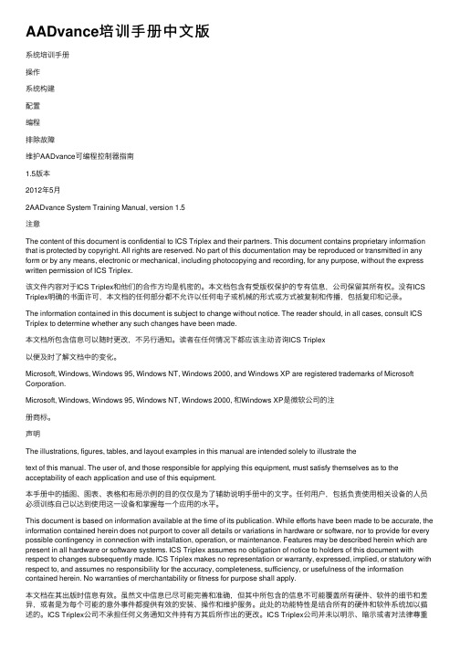
V out
Piston
Core
Coil
Connector
V in
Load Cell
A force transducer or the load cell provides an electrical signal proportional to the amount of force being applied to the specimen being tested. A force sensor has highstrength metal columns with strain gages bonded to it. Load cells use DC conditioners
100 kN Force
Sensor
Load Cell
Sensor Terms: Full-Scale and Range
Full Scale is the maximum allowable value that a measuring device can handle. It is always specified with the device. Ex. Full-scale load for load cells. Range is a voltage amplification of a smaller physical amount.
A phonograph is analog, a music CD is digital
Sensor Conditioner (Calibrated Analog) A to D Converter Digital-Computer Realm
MTS Digital controllers communicate between the computer and the analog devices via Analog to Digital Converters (A2D) and (D2A) The A2D location (and your need to identify it) will vary depending on MTS electronics model, controller model, and type of sensor conditioner. For example, 493 Universal Conditioner has a built-in A2D. But Auxiliary (external conditioner) analog inputs get connected only through an A2D card.
What is a Control Channel?
A control channel commands an axis of actuator movement. Normally, there is one actuator per control channel.
What is a Control Mode?
793 System Operation and Control Pyramid
Test Control
BTW MPT
Your Tests: Procedure, Processes, Control options
Machine Operational Adjustments (Parameter Sets) Software looks for Hardware Components in the test system
Load Unit Front View
Load Unit Rear View
MTS 252 Two Stage Servovalve
Electrical stage creates pressure imbalance which shifts spool
Manifold Spacer
Actuator
Sensor Terms: Feedback/Input
Feedback/Input is the output of a sensor whose output is proportional to its mechanical input. For example, the feedback from a force sensor indicates the amount of force that it is sensing.
MTS 256 Three Stage Servovalve
Accumulator
Dampens hydraulic pressure spikes most noticeable with high frequency, large displacements, high flow
SENSORS AND SIGNALS
Extensometers
An extensometer is a sensor attached to a specimen that measures a dimensional change (gage length or strain) that occurs in the specimen while being tested.
Hardware Overview
» HYDRO-MECHANICAL COMPONENTS » SENSORS AND SIGNALS » CLOSED LOOP CONTROL
Hydraulic Service Manifold With electrically operated valves, the HSM makes hydraulic oil available to the Servovalve. HSM can be mounted on the loadframe or as a stand-alone.
The sensor signal providing information used to control the actuator. Only one control mode can be active at a time per control channel.
Typical Sensors
dc or encoder
Sensor Conditioners in MTS 793 Software
» We select the conditioner in Station Builder » Identified as AC (LVDT) or DC (Load Cell) » The sensor must be calibrated to its conditioner to make a sensor/conditioner pair » Assign the Calibration File in Station Manager
Sensors (Transducers) are used to measure a physical property
LVDT (Linear Variable Differential Transformer)
• Output proportional to position • Transformer with primary and 2 secondary coils. • Displacing core increases mutual inductance between primary and one secondary. • Phase of the output signal indicates direction of displacement. • Excitation is AC
System Components
Closed Loop Control System
Hydraulic Fluid System
Servo Valve Command Closed loop co Command
MTS Controller
Sensor feedback
Hydraulic Power Unit HPU Pump provides fluid flow for the actuator. Temperature and oil level shut off switches protect the pump The Servovalve is the valve that moves the actuator exactly as much as required by the command. It is run by the electronic controller and directs the hydraulic oil to move the actuator in either direction The Actuator applies movement or force to the test specimen. It is what we control with the MTS system software. An actuator will be designed for specific purposes based on maximum speeds, frequencies, or forces. They also have a variety of specimen attachments, sensor locations, and mounting positions.