UXE04140H0AR100中文资料
UXE04140H0AC100中文资料
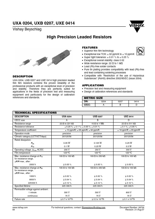
For technical questions, contact: ff3cresistors@Document Number: 28726UXA 0204, UXB 0207, UXE 0414Vishay BeyschlagHigh Precision Leaded ResistorsDESCRIPTIONUXA 0204, UXB 0207 and UXE 0414 high precision leaded thin film resistors combine the proven reliability of the professional products with an exceptional level of precision and stability. Therefore they are perfectly suited for applications in the fields of precision test and measuring equipment and particularly for the design of calibration references and standards.FEATURES•Superior thin film technology•Exceptional low TCR: ± 02 ppm/K to ± 10 ppm/K •Super tight tolerance: ± 0.01 % to ± 0.25 %•Exceptional overall stability: class 0.02•Wide resistance range: 22 Ω to 1 M Ω•Lead (Pb)-free solder contacts•Pure tin plating provides compatibility with lead (Pb)-free and lead containing soldering processes•Compatible with “Restriction of the use of Hazardous Substances” (RoHS) directive 2002/95/EC (issue 2004)APPLICATIONS•Precision test and measuring equipment•Design of calibration references and standardsMETRIC SIZEDIN:020*********CECC:ABDTECHNICAL SPECIFICATIONSDESCRIPTION UXA 0204UXB 0207UXE 0414CECC size AB DResistance range 22 Ω to 221 k Ω10 Ω to 1 M Ω22 Ω to 511 k ΩResistance tolerance ± 0.25 %; ± 0.1 %; ± 0.05 %; ± 0.01 %± 0.1 %; ± 0.05 %Temperature coefficient ± 10ppm/K; ± 05ppm/K; ± 02ppm/K ± 10ppm/K; ± 05ppm/KOperation modeprecision precision precision Climatic category (LCT/UCT/days)20/125/5620/125/5620/125/56Rated dissipation:P 850.05W 0.125 W 0.25 W P 700.1 W 0.25W 0.5W Operating voltage, U max AC/DC 200 V 250 V 300 V Film temperature125°C 125°C 125°C Max. resistance change at P 70for resistance range, ΔR /R max., after:100 Ωto 100 k Ω100 Ωto 250 k Ω100 Ωto 100 k Ω2000h≤ 0.05 %≤ 0.05 %≤ 0.05 %Max. resistance change at P 85for resistance range, ΔR /R max., after:100 Ωto 100 k Ω100 Ωto 250 k Ω100 Ωto 100 k Ω1000h ≤ 0.02 %≤ 0.02 %≤ 0.02 %8000h ≤ 0.04 %≤ 0.04 %≤ 0.04 %225000h≤ 0.12 %≤ 0.12 %≤ 0.12 %Specified lifetime225 000h225 000h225 000hPermissible voltage against ambient :1 minute 300V 500V 800V continuous75V 75V 75V Failure rate≤ 0.7 x 10⁻⁹/h≤ 0.3 x 10⁻⁹/h≤ 0.1 x 10⁻⁹/hDocument Number: 28726For technical questions, contact: ff3cresistors@UXA 0204, UXB 0207, UXE 0414High Precision Leaded ResistorsVishay Beyschlag12NC INFORMATIONComponents may be ordered by using either a simple clear text ordering code, see “Type Description and Ordering Code” or Vishay BCcomponents’ unique 12NC.Numeric Ordering Code (12NC)•The resistors have a 12-digit Part Number starting with 2312.•The subsequent 4digits indicate the resistor type,specification and packaging; see the 12NC Part Number table.•The remaining 4digits indicate the resistance value:–The first 3digits indicate the resistance value.–The last digit indicates the resistance decade in accordance with the 12NC Indicating Resistance Decade table.Last Digit of 12NC Indicating Resistance Decade12NC ExampleThe Part Number of a UXA 0204 resistor, value 47 k Ω and TCR 10 with ± 0.1 % tolerance, supplied on bandolier in a box of 1000 units is: 2312 662 34703.Note:(1) Readable 12NC coding of resistance values is restricted to values with three significant digits. For resistance values with more than three significant digits, a non readable sequential number will be issued by the factory for each requested combination of resistance value and tolerance.RESISTANCE DECADELAST DIGIT10 Ωto 99.9 Ω9100 Ωto 999 Ω11 k Ω to 9.99 k Ω210 k Ωto 99.9 k Ω3100k Ω to 999 k Ω412NC PART NUMBER - resistor type and packagingDESCRIPTIONORDERING CODE 2312........BANDOLIER IN BOX BANDOLIER IN BOX BANDOLIER ON REEL BANDOLIER ON REEL BANDOLIER ON REEL TYPETCRTOL.CU 100 units C1 1000 units R1 1000 units R2 2500 units RP 5000 units UXA 0204± 10 ppm/K± 0.25 %562 2....662 2....462 2....--± 0.1 %562 3....662 3....462 3....--± 0.05 %562 4....662 4....462 4....--± 0.01 %562 7....662 7....462 7....--(1)562 91...662 91...462 91...--± 05 ppm/K± 0.25 %563 2....663 2....463 2....--± 0.1 %563 3....663 3....463 3....--± 0.05 %563 4....663 4....463 4....--± 0.01 %563 7....663 7....463 7....--(1)563 91...663 91...463 91...--± 02 ppm/K± 0.25 %564 2....664 2....464 2....--± 0.1 %564 3....664 3....464 3....--± 0.05 %564 4....664 4....464 4....--± 0.01 %564 7....664 7....464 7....--(1)564 91...664 91...464 91...--UXB 0207± 10 ppm/K± 0.25 %572 2....672 2....472 2....-577 2....± 0.1 %572 3....672 3....472 3....-577 3....± 0.05 %572 4....672 4....472 4....-577 4....± 0.01 %572 7....672 7....472 7....-577 7. (1)572 91...672 91...472 91...-577 91...± 05 ppm/K± 0.25 %573 2....673 2....473 2....-578 2....± 0.1 %573 3....673 3....473 3....-578 3....± 0.05 %573 4....673 4....473 4....-578 4....± 0.01 %573 7....673 7....473 7....-578 7. (1)573 91...673 91....473 91...-578 91...± 02 ppm/K± 0.25 %574 2....674 2....474 2....-579 2....± 0.1 %574 3....674 3....474 3....-579 3....± 0.05 %574 4....674 4....474 4....-579 4....± 0.01 %574 7....674 7....474 7....-579 7. (1)574 91...674 91...474 91...-579 91...UXE 0414± 10 ppm/K± 0.1 %592 3....692 3....-597 3....-± 0.05 %592 4....692 4....-597 4....-(1)592 91...692 91...-597 91...-± 05 ppm/K± 0.1 %593 3....693 3....-598 3....-± 0.05 %593 4....693 4....-598 4....-(1)593 91...693 91...-598 91...- For technical questions, contact: ff3cresistors@Document Number: 28726UXA 0204, UXB 0207, UXE 0414Vishay BeyschlagHigh Precision Leaded ResistorsNotes:(1) Please refer to table PACKAGING, see next page.Products can be ordered using either the Product Description or the 12NC. The PART NUMBER is shown to facilitate the introduction of a unified part numbering system.DIMENSIONSPART NUMBER AND PRODUCT DESCRIPTION UX SERIESPart Numbering: UXB02070F1001AC100MODEL/SIZE SPECIAL CHARACTERTCRVALUETOLERANCE PACKAGINGSPECIALUXA0204UXB0207UXE04140 = neutralH = ± 2 ppm/K G = ± 5 ppm/K F = ± 10 ppm/K3 digit value 1 digit multiplier MULTIPLIER 9 = *10-1 2 = *1020 = *100 3 = *1031 = *1014 = *104T = ± 0.01 %A = ± 0.05 %B = ± 0.1 %C = ± 0.25 %C1CU R1R2RPup to 2 digits 00 = standardProduct Description: UXB 0207-10 0.05 % C1 1K0UXB 0207100.05 %C11K0MODEL SIZE TCR TOLERANCE PACKAGING (1)RESIST ANCE VALUEUXA UXB UXE020*********± 2 ppm/K ± 5 ppm/K ± 10 ppm/K± 0.01 %± 0.05 %± 0.1 %± 0.25 %C1CU R1R2RP1K0 = 1.0 k Ω47K = 47 k Ω50R5 = 50.5 ΩDIMENSIONS - leaded resistor types, mass and relevant physical dimensionsTYPE D max (mm)L max (mm)d nom (mm)I min (mm)M min (mm)MASS (mg)UXA 0204 1.6 3.60.529.0 5.0125UXB 0207 2.5 6.30.628.07.5220UXE 04144.011.90.831.015.0750SCRIPT MARKING - printed resistance value and letter coding for TCR and toleranceRESISTANCE VALUETOL.(%)LETTER CODETCR (ppm/K)LETTER CODEClear text code for value± 0.25C ± 10B ± 0.1B ± 05A ± 0.05A ± 02T ± 0.01T−−B 0200F 17UX 00A C 110Document Number: 28726For technical questions, contact: ff3cresistors@UXA 0204, UXB 0207, UXE 0414High Precision Leaded ResistorsVishay BeyschlagNotes:(1) Resistance values to be selected from the E192 series, for other values please contact the factory.(2) TCR 10 and TCR 05 are specified over the temperature range from - 20°C to + 85°C.(3) TCR 02 is specified over the temperature range from 0°C to + 60°C.DESCRIPTIONProduction is strictly controlled and follows an extensive set of instructions established for reproducibility. A homogeneous film of metal alloy is deposited on a high grade ceramic body (85 % Al 2O 3) and conditioned to achieve the desired temperature coefficient. Nickel plated steel termination caps are firmly pressed on the metallized rods.Special laser devices are used repeatedly to achieve the target value by slowly and smoothly cutting a helical groove in the resistive layer without damaging the ceramics. A further conditioning is applied in order to stabilise the trimming result. Connecting wires of electrolytic copper plated with pure tin are welded to the termination caps. The resistors are covered by protective coating designed for electrical, mechanical and climatic protection.The terminations receive a final pure tin on nickel plating. Script marking designates the resistance value plus coded TCR and tolerance.The result of the determined production is verified by an accelerated ageing (burn-in) and extensive testing procedure performed on 100 % of the individual resistors.Only accepted products are stuck directly on the adhesive tapes in accordance with IEC 60286-1.ASSEMBLYThe resistors are suitable for processing on automatic insertion equipment and cutting and bending machines.E xcellent solderability is proven, even after extended storage. They are suitable for automatic soldering using wave or dipping. The encapsulation is resistant to all cleaning solvents commonly used in the electronics industry,including alcohols, esters and aqueous solutions. The suitability of conformal coatings, if applied, shall be qualified by appropriate means to ensure the long-term stability of the whole system.APPROVALSWhere applicable, the resistors are tested in accordance with CECC 40101-806 which refers to EN 60115-1 and EN 140100.Vishay B EYSCHLAG has achieved "Approval of Manufacturer" in accordance with EN 100114-1PACKAGINGMODEL REELBOXBANDOLIER ON REELCODE PIECES/BOXCODE UXA 1000R11001000CU C1UXB 10005000R1RP 1001000CU C1UXE2500R21001000CU C1TEMPERATURE COEFFICIENT AND RESISTANCE RANGEDESCRIPTIONRESISTANCE VALUE (1)TCRTOLERANCE UXA 0204UXB 0207UXE 0414± 10 ppm/K (2)± 0.25 %22 Ω to 221 k Ω10 Ω to 1 M Ω-± 0.1 %43 Ω to 221 k Ω10 Ω to 1 M Ω22 Ω to 511k Ω± 0.05 %100 Ω to 180 k Ω24 Ω to 301 k Ω100 Ω to 301k Ω± 0.01 %200 Ω to 150 k Ω24 Ω to 301 k Ω-± 05 ppm/K (2)± 0.25 %47 Ω to 150 k Ω10 Ω to 1 M Ω-± 0.1 %47 Ω to 150 k Ω10 Ω to 1 M Ω47 Ω to 301k Ω± 0.05 %100 Ω to 150 k Ω24Ω to 221 k Ω100 Ω to 301k Ω± 0.01 %200 Ω to 150 k Ω24 Ω to 221 k Ω-± 02 ppm/K (3)± 0.25 %100 Ω to 100 k Ω100 Ω to 150 k Ω-± 0.1 %100 Ω to 100 k Ω100 Ω to 150 k Ω-± 0.05 %150 Ω to 100 k Ω150 Ω to 150 k Ω-± 0.01 %200 Ω to 100 k Ω200 Ω to 150 k Ω- For technical questions, contact: ff3cresistors@Document Number: 28726UXA 0204, UXB 0207, UXE 0414Vishay BeyschlagHigh Precision Leaded ResistorsFUNCTIONAL DESCRIPTIONDerating - Precision OperationTemperature RiseDocument Number: 28726For technical questions, contact: ff3cresistors@UXA 0204, UXB 0207, UXE 0414High Precision Leaded ResistorsVishay BeyschlagTESTS AND REQUIREMENTSE ssentially all tests are carried out in accordance with the following specifications:E N 140000/IE C 60115-1, Generic specification (includes tests)E N 140100/IE C 60115-2, Sectional specification (includes schedule for qualification approval)CECC 40101-806, Detail specification (includes schedule for conformance inspection)Most of the components are approved in accordance with the uropean CE CC-system, where applicable. The Test Procedures and Requirements table contains only the most important tests. For the full test schedule refer to the documents listed above. The testing also covers most of the requirements specified by EIA/IS-703 and JIS-C-5202.The tests are carried out in accordance with IEC 60 068 and under standard atmospheric conditions in accordance withIE C 60068-1, 5.3. Climatic category LCT/UCT/56 (rated temperature range: Lower Category Temperature, Upper Category Temperature; damp heat, long term, 56 days) is valid.Unless otherwise specified the following values apply:Temperature: 15 °C to 35 °C Relative humidity: 45 % to 75 %Air pressure: 86 kPa to 106 kPa (860 mbar to 1060 mbar).For testing the components are mounted on a test board in accordance with IE C 60115-1, 4.31 unless otherwise specified.In the Test Procedures and Requirements table only the tests and requirements are listed with reference to the relevant clauses of IEC 60115-1 and IEC 60068-2; a short description of the test procedure is also given.TEST PROCEDURES AND REQUIREMENTSIEC 60115-1CLAUSEIEC 60068-2TEST METHODTESTPROCEDUREREQUIREMENTSPERMISSIBLE CHANGE (ΔR )Stability for product types:UXA 0204100 Ω to 100 k Ω22Ω to < 100Ω;> 100 k Ω to 221 k Ω -UXB 0207100 Ω to 250 k Ω40.2Ω to < 100 Ω;> 250k Ω to 301 k Ω10Ω to < 40.2 Ω;> 301 k Ω to 1 M ΩUXE 0414100 Ω to 100 k Ω22Ω to < 100 Ω;> 100k Ω to 511 k Ω-4.5-resistance (ΔR /R )± 0.25 %; ± 0.1 %; ± 0.05 %; ± 0.01 %4.8.4.2-temperature coefficientat 20/LCT/20 °C and 20/UCT/20 °C± 10 ppm/K; ± 05 ppm/K; ± 02 ppm/K4.25.1-enduranceroom temperature;U = orU = U max ;1.5 h on; 0.5 h off 70°C; 2000 h ± (0.05 %R +0.01Ω)± (0.05 %R +0.01Ω)± (0.05 %R +0.01Ω)85°C; 1000 h ± (0.02 %R +0.01Ω)± (0.03 %R +0.01Ω)±(0.04 %R +0.01Ω)85°C; 8000 h± (0.04 %R +0.01Ω)± (0.06 %R +0.01Ω)± (0.08 %R +0.01Ω)P 70 x R For technical questions, contact: ff3cresistors@Document Number: 28726UXA 0204, UXB 0207, UXE 0414Vishay BeyschlagHigh Precision Leaded Resistors4.25.3-endurance atupper category temperature 125°C; 1000 h ± (0.04 % R +0.01Ω)± (0.06 %R +0.01Ω)± (0.08 %R +0.01Ω)4.24 3 (Ca)damp heat,steady state (40± 2)°C; 56days; (93 ± 3) %RH± (0.04 %R +0.01Ω)± (0.05 %R +0.01Ω)± (0.06 %R +0.01Ω)4.23climatic sequence:4.23.22 (Ba)dry heat 125°C; 16h 4.23.330 (Db)damp heat, cyclic55°C; 24h;90% to 100%RH;1 cycle4.23.4 1 (Aa)cold - 55 °C; 2h 4.23.513 (M)low air pressure 8.5kPa;2h;15 °C to 35°C 4.23.630 (Db)damp heat, cyclic55°C; 5days;95% to 100%RH;5 cycles ± (0.04 %R +0.01 Ω)no visible damage± (0.05 %R +0.01Ω)no visible damage± (0.06 %R +0.01Ω)no visible damage4.13-short time overload room temperature;U = 2.5 x or U = 2x U max ; 5 s ± (0.01 %R +0.01Ω)no visible damage ± (0.01 %R +0.01Ω)no visible damage ± (0.02 %R +0.01Ω)no visible damage4.1914 (Na)rapid change of temperature 30minutes at LCT and 30minutes at UCT;5cycles ± (0.01 %R +0.01Ω)no visible damage ± (0.01 %R +0.01Ω)no visible damage ± (0.02 % R +0.01Ω)no visible damage4.2945 (XA)component solvent resistanceisopropyl alcohol + 23 °C; toothbrushmethod marking legible;no visible damage4.18.220 (Tb)resistance to soldering heat unmounted components; (260± 5)°C; (10± 1)s ± (0.01 % R +0.01Ω)no visible damage ± (0.01 %R +0.01Ω)no visible damage ± (0.02 %R +0.01Ω)no visible damage4.1720 (T a)solderability + 235°C; 2 s solderbath methodgood tinning (Š 95 % coverage, no visible damage)TEST PROCEDURES AND REQUIREMENTSIEC 60115-1CLAUSEIEC 60068-2TEST METHODTESTPROCEDUREREQUIREMENTSPERMISSIBLE CHANGE (ΔR )Stability for producttypes:UXA 0204100 Ω to 100 k Ω22Ω to < 100Ω;> 100 k Ω to 221 k Ω -UXB 0207100 Ω to 250 k Ω40.2Ω to < 100 Ω;> 250k Ω to 301 k Ω10Ω to < 40.2 Ω;> 301 k Ω to 1 M ΩUXE 0414100 Ω to 100 k Ω22Ω to < 100 Ω;> 100k Ω to 511 k Ω-P 70 x RDocument Number: 28726For technical questions, contact: ff3cresistors@UXA 0204, UXB 0207, UXE 0414High Precision Leaded ResistorsVishay Beyschlag4.226 (B4)vibration6 h; 10 Hz to 2000 Hz 1.5 mm or 196 m/s 2± (0.01 %R +0.01Ω)± (0.01 %R +0.01Ω)± (0.02 %R +0.01Ω)4.1621 (Ua 1)21 (Ub)21 (Uc)robustness ofterminations tensile, bending andtorsion ± (0.01 %R +0.01Ω)± (0.01 %R +0.01Ω)±(0.02%R +0.01Ω)4.7-voltage proofU RMS = 100 V; 60 sno flashover or breakdownTEST PROCEDURES AND REQUIREMENTSIEC 60115-1CLAUSEIEC 60068-2TEST METHODTESTPROCEDUREREQUIREMENTSPERMISSIBLE CHANGE (ΔR )Stability for product types:UXA 0204100 Ω to 100 k Ω22Ω to < 100Ω;> 100 k Ω to 221 k Ω -UXB 0207100 Ω to 250 k Ω40.2Ω to < 100 Ω;> 250k Ω to 301 k Ω10Ω to < 40.2 Ω;> 301 k Ω to 1 M ΩUXE 0414100 Ω to 100 k Ω22Ω to < 100 Ω;> 100k Ω to 511 k Ω-Legal Disclaimer NoticeVishay Document Number: NoticeSpecifications of the products displayed herein are subject to change without notice. Vishay Intertechnology, Inc., or anyone on its behalf, assumes no responsibility or liability for any errors or inaccuracies.Information contained herein is intended to provide a product description only. No license, express or implied, by estoppel or otherwise, to any intellectual property rights is granted by this document. Except as provided in Vishay's terms and conditions of sale for such products, Vishay assumes no liability whatsoever, and disclaims any express or implied warranty, relating to sale and/or use of Vishay products including liability or warranties relating to fitness for a particular purpose, merchantability, or infringement of any patent, copyright, or other intellectual property right. The products shown herein are not designed for use in medical, life-saving, or life-sustaining applications. Customers using or selling these products for use in such applications do so at their own risk and agree to fully indemnify Vishay for any damages resulting from such improper use or sale.。
中英文对照新普利斯消防报警主机4100U说明
中英文对照新普利斯消防报警主机4100U说明苏金明联系电话187********Simplex 4100UUniversal Fire Alarm PlatformSimplex 4100U 通用消防报警系统Product OverviewThe Simplex? 4100U Fire Detection and Alarm Platform is a high-end, next-generation distributed network system that combines superior fire protection and information management with lower costs of installation, maintains and ownership.产品概况:Simplex? 4100U火灾自动探测和报警系统是一个高效,新一代的分布式网络系统,包含高等级的火灾保护,信息管理和低成本的安装,维护。
The 4100U builds upon the field-proven performance of the industry-leading Simplex? 4100 Series fire detection systems. The 4100U features expanded point capacity, digital voice communications, advanced built-in diagnostics, dual operating software, and other enhancements. Built-in compatibility with existing 4100 and 4120 network systems allows easy upgrade to 4100U technology.新的4100U更新延续了原有的Simplex? 4100系列产品,扩展了地址容量,增加数码广播,先进的自我诊断功能,冗余的操作系统软件以及其他的增加。
霍尼韦尔空气净化电子样本
600×442×162mm
16.4kg(运输) 14kg(安装)
UL 认证
F58G 空调箱适配型电子空气净化机
特性:
• 每个单元最大处理容量2000cfm(3400m3/h) • 多个单元可组成排列的空气净化机 • 指示灯可显示正常运行及故障情形 • 可与楼宇管理系统连接使用 • 电镀的机箱可防止生锈 • 测试按钮检查系统运行 • 预过滤网保护电子单元不受大颗粒污染 • 可有效去除悬浮在空气中直径为0.3μ的微粒 • 可与紫外线灯配套应用 • 发生误操作或电子单元需要清洗时,电子继电器将停止工作 • 电子单元在相当范围内负载时,固态电源供应组合可自我调
性能参数表
型号 电子单元数量 处理风量 安装方式 面板 / 格栅形式
组成
电源 运行环境 尺寸 重量 认证
F52G1012
F52G2002
1
1000cfm (1700m3/h)
回风口型
百叶
固态电源供应组合, 电子单元,预过滤网,格栅
电子单元,预过滤网,格栅
220V/50Hz
无电源供应
40oF-125oF (4oC-52oC)
740×485×273mm
31.5kg(运输) 29.5kg(安装)
18.5kg(运输) 16kg(安装)
UL 认证
CE 认证
F57A/B 嵌入式电子空气净化机
特性:
• 三速电机驱动循环风机 F57A额定处理风量可达875cfm (1500m3/h) F57B额定处理风量可达460cfm (782m3/h)
做为整体过敏症治疗方案中的一部分,Honeywell电子空气净化机的应用可以减轻过敏症和其它呼吸问题给患 者带来的伤害。然而,并不是所有类型的空气净化机都能达到此处理效果。
海外规格仕样书第4版(中文)
4.在机铭板上标示出以下内容 ・制造者名 ・制造年月 ・形式以及model编号 ・定格电源电压(电压、位相、周波数、最大负荷电流、etc) 在电源上不可以用「AC200V」表示,而要用「~200V」表示 ・气压(定格压力) ・原产地表示(MADE IN JAPAN等) 注)FA标准机铭板: 4—710—156—01(大—11) 带孔、by三立产业 EN60204 UL1740
8.盖子、马达框架、trans core、电装品筐体、以及接续管等的金属部, 如果和地线或金属接触,会导致和物品本身的导通。
EN60204、UL1740
7/28
要求事项
1.电源切断装置要使用得到认可的漏电断路器、自动断路器、线路保护器 EN60204、UL1740 2.主断路器的定格要遵循以下事项。 EN60204、UL1740 a)电流容量:最大负荷电流的115%以上,或者使用的导线的要求容许电流以下 (14配线以及电路——参照17) b)切断容量:在机器上使用的马达中,最大马达的 rotor rock电流+其他装置的 最大负荷电流以上 3.电力引入线(一次电源)要直接和断路器连接 EN60204、UL1740 4.电源切断装置遵循一下事项。 EN60204、UL1740 (a)安装把手,方便从外部操作 (b)把手的中心高度在0.6~1.9以内 (c)要有OFF锁定机能.(可以上锁的构造) (d)门关上时要有ON/OFF的明确指示 (e)ON/OFF可以用「O」也可以用「I」来表示 (f)接地导线以外所有的相要同时切断 (g)主断路器上如果没有OFF锁定机能,要在负荷侧设定带钥匙的主开关。
贵社 check
本社 check
备注
① 外 观 以 及 构 造 的 规 定
4/28
sun fire x4140、x4240 和 x4440 服务器产品说明书
Sun Microsystems, Inc.请将有关本文档的意见和建议提交至:/hwdocs/feedbackSun Fire™ X4140、X4240 和 X4440服务器产品说明文件号码 820-5228-112008 年 7 月,修订版 A版权所有 © 2008 Sun Microsystems, Inc., 4150 Network Circle, Santa Clara, California 95054, U.S.A. 保留所有权利。
未出版 - 保留美国版权法规定的所有权利。
本产品包含 SUN MICROSYSTEMS, INC. 的机密信息和商业机密。
未经 SUN MICROSYSTEMS, INC. 的事先明确书面许可,不得使用、公开或进行复制。
本发行版本可能包含由第三方开发的内容。
Sun、Sun Microsystems、Sun 徽标、Java、Solaris、Sun Fire 4140、Sun Fire 4240 和 Sun Fire 4440 是 Sun Microsystems, Inc. 在美国和其它国家/地区的商标或注册商标。
AMD Opteron 和 Opteron 是 Advanced Micro Devices, Inc. 的商标。
Intel 是 Intel Corporation 的注册商标。
本产品受美国出口控制法律制约,并应遵守其他国家/地区的进出口法律。
严禁将本产品直接或间接地用于核设施、导弹、生化武器或海上核设施,也不能直接或间接地出口给核设施、导弹、生化武器或海上核设施的最终用户。
严禁出口或转口到美国禁运的国家/地区以及美国禁止出口清单中所包含的实体,包括但不限于被禁止的个人以及特别指定的国家/地区的公民。
对任何使用 CPU 备件或更换件的使用仅限于对遵照美国出口法律出口的产品中的 CPU 进行修复或一对一更换。
除非经过美国政府授权,否则,严禁将 CPU 用于产品升级。
ET4000中文资料
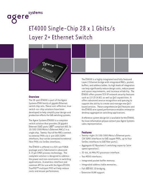
OverviewThe 28-port E T4000 is part of the Agere Systems E T4K family of gigabit E thernet switch chip sets. These cost-effective, true switch-on-chip solutions have beendeveloped to help simplify your design and production efforts for Gb E switching systems.The Agere Systems E T4000 is a complete switch solution that provides 28 gigabit E thernet (Gb E ) ports (I EEE ® compliant 802.3z 10/100/1000 Mbits/s E thernet MACs) in a single chip. Twenty-four of the MACs connect to external PHYs via 6-pin LVDS SGMII interfaces, four can be connected to external fiber PHYs via SerDes interfaces.The E T4000 is offered in a 525-pin FCBGA package and is fabricated in advanced 0.13 µm CMOS process technology. The complete solution is designed to address the power and size constraints in switching applications. A seamless interface and common API for use with the Agere E T1081TruePHY ™ multiport PHY will help reduce costs and ensure performance.E T4000 offers proven TCP/IP network security features such as L2/L3/L4 ACL as well as QoS capabilities. It offers advanced service recognition and queuing to support the ability to create and manage new QoS-based services. These comprehensive QoS features and the E T4000 wire speed performance enables enterprise desktop aggregation switching applications.A reference system design kit is available for the E T4000,for more information please contact your Agere Systems sales representative.Features•Twenty-eight 10/100/1000 Mbits/s E thernet ports (24 SGMII interfaces to Gb E copper PHYs, up to four SerDes interfaces to Gb E fiber ports).•Aggregate 42 Mpackets/s switching capacity (wire speed operation).•32-bit, 66 MHz PCI processor interface.•Two MDIO interfaces.•Integrated packet buffer memory.•Integrated address table memories.•Full I EEE 802.1D bridging.•E xtensive VLAN support.E T4000 Single-Chip 28 x 1 Gbits/s Layer 2+ E thernet Switch•L2/L3/L4 classification for access control list (ACL) and quality of service (QoS).•Supporting IPv4 and IPv6•Advanced traffic management functions.•Link aggregation and mirroring.•Advanced 0.13 µm CMOS technology.•525-pin FCBGA package.ApplicationsThe Agere Systems E T4000 chip set solutions are used to create competitive Layer 2+ gigabit E thernet desktop switches. They can be used for a 24-port port gigabit E thernet switch in standalone configuration, or with the addition of four fiber ports in standalone configuration, or in high-density gigabit E thernet fabric switches.For additional information, contact your Agere Systems Account Manager or the following:INT E RN E T: E -MAIL:docmaster@N. AM E RICA:Agere Systems Inc., Lehigh Valley Central Campus, Room 10A-301C, 1110 American Parkway N E , Allentown, PA 18109-91381-800-372-2447, FAX 610-712-4106 (In CANADA: 1-800-553-2448, FAX 610-712-4106)ASIA: CHINA: (86) 21-54614688 (Shanghai), (86) 755-25881122 (Shenzhen)JAPAN: (81) 3-5421-1600 (Tokyo), KOR E A: (82) 2-767-1850 (Seoul), SINGAPOR E : (65) 6778-8833, TAIWAN: (886) 2-2725-5858 (Taipei)E UROP E :Tel. (44) 1344 296 400Agere Systems Inc. reserves the right to make changes to the product(s) or information contained herein without notice. No liability is assumed as a result of their use or application.Agere, Agere Systems, the Agere logo, and TruePHY are trademarks of Agere Systems Inc.Copyright © 2004 Agere Systems Inc.All Rights Reserved June 2004BC04-023GSWCFeatures (continued)System DiagramI EEE is a registered trademark of the Institute of E lectrical and E lectronics E ngineers, Inc.24 Port Switch-24 10/100/1000M Copper Ports -4 Gb E SFP PortsSerDes。
Schneider Electric XUSL4E14F031N 产品数据手册说明书

T h e i n f o r m a t i o n p r o v i d e d i n t h i s d o c u m e n t a t i o n c o n t a i n s g e n e r a l d e s c r i p t i o n s a n d /o r t e c h n i c a l c h a r a c t e r i s t i c s o f t h e p e r f o r m a n c e o f t h e p r o d u c t s c o n t a i n e d h e r e i n .T h i s d o c u m e n t a t i o n i s n o t i n t e n d e d a s a s u b s t i t u t e f o r a n d i s n o t t o b e u s e d f o r d e t e r m i n i n g s u i t a b i l i t y o r r e l i a b i l i t y o f t h e s e p r o d u c t s f o r s p e c i f i c u s e r a p p l i c a t i o n s .I t i s t h e d u t y o f a n y s u c h u s e r o r i n t e g r a t o r t o p e r f o r m t h e a p p r o p r i a t e a n d c o m p l e t e r i s k a n a l y s i s , e v a l u a t i o n a n d t e s t i n g o f t h e p r o d u c t s w i t h r e s p e c t t o t h e r e l e v a n t s p e c i f i c a p p l i c a t i o n o r u s e t h e r e o f .N e i t h e r S c h n e i d e r E l e c t r i c I n d u s t r i e s S A S n o r a n y o f i t s a f f i l i a t e s o r s u b s i d i a r i e s s h a l l b e r e s p o n s i b l e o r l i a b l e f o r m i s u s e o f t h e i n f o r m a t i o n c o n t a i n e d h e r e i n .Product data sheetCharacteristicsXUSL4E14F031NXUSL type 4 - Finger protection - Std sensingrange - Hp = 310 mm, R=14mmProduct availability: Non-Stock - Not normally stocked in distribution facilityMainRange of product Preventa Safety detection Product or component typeSafety light curtain type 4Device short name XUSL4EOutput type2 safety outputs OSSD solid-state PNP arc suppres-sion)Product specific applica-tionFor finger protection [R] Resolution 0.55 in (14 mm)[Sn] nominal sensing distance3.28…19.69 Ft (1…6 m) by cabling 0.00…9.84 ft (0…3 m) by cabling [Hp] Height protected 12.20 in (310 mm)Number of beams 30Type of start / restart Manual Automatic External Device Moni-toring (EDM)Selected by wiringComplementaryDetection system Transmitter-receiver system Response time 5.5 msKit compositionAdjustable mounting bracket(s)1 receiver(s)1 transmitter(s)1 user guide with certificate of conformity on CD-ROM [EAA] effective aperture angle 2.5 ° at 3 mEmissionIR LED 0.000037402 in (950 nm)[Us] rated supply voltage 24 V DC +/- 20 %SupplyPower supply IEC 61496-1Power supply IEC 60204-1[Ie] rated operational current 2 ACurrent consumption42 mA no-load transmitter 83 mA no-load receiver 42 mA transmitter900 mA with maximum load receiver Output current limits 0.4 A safety outputs OSSD Output voltage 24 V Output circuit type DC Maximum voltage drop <0.5 VLocal signalling 1 multi-colour LED transmitter 2 dual colour LEDs receiverElectrical connection 1 male connector M12 5 pins transmitter 1 male connector M12 8 pins receiverFunction availableTestMuting through external safety module XPSLCMUT1160LED display of operating modes and faults Marking CEMaterialAluminium casingPolycarbonate front panel Polypropylene end caps Housing colourRed RAL 3000Fixing mode By fixing bracketsNet weight 1.54 lb(US) (0.7 kg)Offer type Standard distanceEnvironmentDirectives89/336/EEC - electromagnetic compatibility2002/95/EC - RoHS directive98/37/EEC - machinery89/655/EEC - work equipment2002/96/EC - WEEE directiveProduct certifications CULusCETÜVSafety level (correctly wired)Type 4 IEC 61496-1SIL 3 IEC 61508SILCL 3 IEC 62061Category 4 EN/ISO 13849-1PL = e EN/ISO 13849-1Optical characteristic Resistance to light disturbance EN/IEC 61496-2Mission time20 year(s)Safety reliability data PFHd = 1.27E-8 1/h IEC 61508Ambient air temperature for operation-10…55 °C (14…131 °F)-4…131 °F (-20…55 °C)Ambient air temperature for storage-31…158 °F (-35…70 °C)-25…70 °C (-13…158 °F)Relative humidity0…95 % without condensationIP degree of protection IP65IP67Shock resistance10 gn 16 ms IEC 61496-1Vibration resistance0.35 +/- 0.05 mm 10…55 Hz)IEC 61496-1Ordering and shipping detailsCategory22455 - LIGHT CURTAINS - XUSLDiscount Schedule DS2GTIN00785901735632Package weight(Lbs) 1.58 kg (3.49 lb(US))Returnability YesCountry of origin ITOffer SustainabilitySustainable offer status Green Premium productREACh Regulation REACh DeclarationEU RoHS Directive Pro-active compliance (Product out of EU RoHS legal scope)EU RoHS Decla-rationToxic heavy metal free YesMercury free YesRoHS exemption information YesEnvironmental Disclosure Product Environmental ProfileCircularity Profile End Of Life InformationContractual warrantyWarranty18 monthsDimensions Drawings DimensionsBrackets DimensionsMounting and Clearance Mounting and Clearance(1)Insert(2)Bracket(3)Washer(4)Spring washer(5)NutConnections and SchemaWiring DiagramsTransmitter Connections(1)+24 Vdc(2)Configuration_0(3)0 Vdc(4)Configuration_1(5)FEReceiver Connections(1)OSSD1(2)+ 24 V(3)OSSD2(4)Configuration_A(5)K1_K2 Feeback/Restart(6)Configuration_B(7)0 Vdc(8)FEReceiver Configurations and Operating ModesAutomatic Start/RestartWithout External Device Monitoring (EDM) feedback loopWith External Device Monitoring (EDM) feedback loopManual Start/RestartWithout External Device Monitoring (EDM) feedback loop(1)RestartWith External Device Monitoring (EDM) feedback loop(1)RestartConnecting to a Safety Interface1 :Click on Download & Documents2 :Click on Application solutionsTo have all connection schematics concerning our safety module, select "download and document" and download the file "Safety lightcurtains association with safety interfaces"。
STPS140U中文资料
STPS140A/U®July 1998 - Ed: 6BPOWER SCHOTTKY RECTIFIERI F(AV) 1 A V RRM 40 V V F (max)0.5 VMAIN PRODUCT CHARACTERISTICSVERY SMALL CONDUCTION LOSSES NEGLIGIBLE SWITCHING LOSSES LOW FORWARD VOLTAGE DROP SURFACE MOUNTED DEVICE FEATURES AND BENEFITSSingle chip Schottky rectifier suited for Switch-mode Power Supplies and high frequency DC to DC converters.Packaged in SMA and SMB(*), this device is in-tended for surface mounting and used in low volt-age, high frequency inverters, free wheeling and polarity protection applications.(*) in accordance with DO214AAand DO21AC JEDECDESCRIPTIONSMB STPS140USymbol ParameterValue Unit V RRM Repetitive peak reverse voltage40V I F(RMS)RMS forward current7A I F(AV)Average forward current δ = 0.5 SMA T L = 130°C 1ASMBT L = 135°C I FSM Surge non repetitive forward current tp = 10 ms Sinusoidal 60A I RRM Repetitive peak reverse current tp = 2 µs F = 1kHz1A I RSM Non repetitive peak reverse current tp = 100µs square1A T stg Storage temperature range - 65 to + 150°CTj Maximum junction temperature 150dV/dtCritical rate of rise of reverse voltage10000V/µs ABSOLUTE RATINGS (limiting values)SMA STPS140A 1/6Symbol ParameterValue Unit R th (j-l)Junction to leadSMA 30°C/WSMB25THERMAL RESISTANCES Symbol Tests Conditions Tests Conditions Min.Typ.Max.Unit I R *Reverse leakage currentTj = 25°C V R = 40V12µA Tj = 100°C0.252mA V F **Forward voltage dropTj = 25°C I F = 1 A 0.55VTj = 125°C I F = 1 A 0.430.5Tj = 25°C I F = 2 A 0.65Tj = 125°CI F = 2 A0.530.6STATIC ELECTRICAL CHARACTERISTICS Pulse test :* tp = 5 ms, δ < 2 %** tp = 380 µs, δ < 2%To evaluate the maximum conduction losses use the following equation :P = 0.4 x I F(AV) + 0.10 x I F 2(RMS)0.00.20.40.60.81.01.20.00.10.20.30.40.50.60.7IF(av) (A)PF(av)(W)= 0.2δ= 0.5δ= 1δδ= 0.05= 0.1δTδ=tp/TtpFig. 1: Average forward power dissipation versus average forward current.02550751001251500.00.20.40.60.81.01.2Tamb(°C)IF(av)(A)Rth(j-a)=Rth(j-l)SMARth(j-a)=100°C/W S(Cu)=1.5cm²SMBRth(j-a)=80°C/W S(Cu)=1.5cm²Tδ=tp/TtpFig. 2: Average forward current versus ambient temperature (δ=0.5).STPS140A/U2/61E-31E-21E-11E+0012345678t(s)IM(A)T a=25°CT a=50°CT a=100°CI Mtδ=0.5Fig. 3-1: Non repetivesurge peak forward current versus overload duration (maximum values) (SMB).1E-31E-21E-11E+0012345678T a=25°CT a=50°C T a=100°Ct(s)IM(A)I Mtδ=0.5Fig. 3-2: Non repetivesurge peak forward current versus overload duration (maximum values) (SMA).1E-21E-11E+01E+11E+21E+30.00.10.20.30.40.50.60.70.80.91.0tp(s)Zth(j-a)/Rth(j-a)Single pulse Printed circuit board:SCu=1.5cm (e=35µm)2= 0.1δ= 0.2δ= 0.5δTδ=tp/TtpFig. 4-1: Relative variation of thermal impedance junction to ambient versus pulse duration (SMB).1E-21E-11E+01E+11E+20.00.10.20.30.40.50.60.70.80.91.0Zth(j-a)/Rth(j-a)Single pulse= 0.1δ= 0.2δ= 0.5δTδ=tp/Ttptp(s)Printed circuit board:SCu=1.5cm (e=35µm)2Fig. 4-2: Relative variation of thermal impedancejunction to ambient versus pulse duration (SMA).05101520253035401E-21E-11E+01E+11E+21E+3VR(V)IR(µA)Tj=125°CTj=75°CTj=25°C Fig. 5: Reverse leakage current versus reversevoltage applied (typical values).125102050102050100200C(pF)F=1MHz Tj=25°CVR(V)Fig. 6: Junction capacitance versus reverse voltage applied (typical values)STPS140A/U3/60.00.10.20.30.40.50.60.70.80.9 1.01E-21E-11E+01E+1VFM(V)IFM(A)Tj=125°CFig. 7: Forward voltage drop versus forward current (maximum values).1234520406080100120S(Cu) (cm²)Rth(j-a) (°C/W)P=1.5WFig. 8-1: Thermal resistance junction to ambient versus copper surface under each lead (Epoxy printed circuit board, copper thickness: 35µm)(SMB).12345020406080100120140P=1.5WS(Cu) (cm²)Rth(j-a) (°C/W)Fig. 8-2: Thermal resistance junction to ambient versus copper surface under each lead (Epoxy printed circuit board, copper thickness: 35µm)(SMA).STPS140A/U4/6PACKAGE MECHANICAL DATA SMAECLE1DA1A2bREF.DIMENSIONSMillimeters Inches Min.Max.Min.Max.A11.902.700.0750.106A20.050.200.0020.008b 1.25 1.650.0490.065c0.150.410.0060.016E4.805.600.1890.220E1 3.95 4.600.1560.181D2.25 2.950.0890.116L0.751.600.0300.063Marking: S140FOOT PRINT (in millimeters)2.40 1.651.45 1.45STPS140A/U5/6Information furnished is believed to be accurate and reliable. However, STMicroelectronics assumes no responsibility for the consequences of use of such information nor for any infringement of patents or other rights of third parties which may result from its use. No license is granted by implication or otherwise under any patent or patent rights of STMicroelectronics. Specifications mentioned in this publication are subject to change without notice. This publication supersedes and replaces all information previously supplied.STMicroelectronics products are not authorized for use as critical components in life support devices or systems without express written ap-proval of STMicroelectronics.The ST logo is a registered trademark of STMicroelectronics © 1999 STMicroelectronics - Printed in Italy - All rights reserved.STMicroelectronics GROUP OF COMPANIESAustralia - Brazil - China - Finland - France - Germany - Hong Kong - India - Italy - Japan - MalaysiaMalta - Morocco - Singapore - Spain - Sweden - Switzerland - United Kingdom - U.S.A.PACKAGE MECHANICAL DATA SMB PlasticECLE1DA1A2bREF.DIMENSIONSMillimeters Inches Min.Max.Min.Max.A11.902.450.0750.096A20.050.200.0020.008b 1.95 2.200.0770.087c0.150.410.0060.016E5.10 5.600.2010.220E1 4.05 4.600.1590.181D3.30 3.950.1300.156L0.751.600.0300.063FOOT PRINT (in millimeters)Marking: G141.522.75 2.31.52STPS140A/U6/6。
- 1、下载文档前请自行甄别文档内容的完整性,平台不提供额外的编辑、内容补充、找答案等附加服务。
- 2、"仅部分预览"的文档,不可在线预览部分如存在完整性等问题,可反馈申请退款(可完整预览的文档不适用该条件!)。
- 3、如文档侵犯您的权益,请联系客服反馈,我们会尽快为您处理(人工客服工作时间:9:00-18:30)。
For technical questions, contact: ff3cresistors@Document Number: 28726UXA 0204, UXB 0207, UXE 0414Vishay BeyschlagHigh Precision Leaded ResistorsDESCRIPTIONUXA 0204, UXB 0207 and UXE 0414 high precision leaded thin film resistors combine the proven reliability of the professional products with an exceptional level of precision and stability. Therefore they are perfectly suited for applications in the fields of precision test and measuring equipment and particularly for the design of calibration references and standards.FEATURES•Superior thin film technology•Exceptional low TCR: ± 02 ppm/K to ± 10 ppm/K •Super tight tolerance: ± 0.01 % to ± 0.25 %•Exceptional overall stability: class 0.02•Wide resistance range: 22 Ω to 1 M Ω•Lead (Pb)-free solder contacts•Pure tin plating provides compatibility with lead (Pb)-free and lead containing soldering processes•Compatible with “Restriction of the use of Hazardous Substances” (RoHS) directive 2002/95/EC (issue 2004)APPLICATIONS•Precision test and measuring equipment•Design of calibration references and standardsMETRIC SIZEDIN:020*********CECC:ABDTECHNICAL SPECIFICATIONSDESCRIPTION UXA 0204UXB 0207UXE 0414CECC size AB DResistance range 22 Ω to 221 k Ω10 Ω to 1 M Ω22 Ω to 511 k ΩResistance tolerance ± 0.25 %; ± 0.1 %; ± 0.05 %; ± 0.01 %± 0.1 %; ± 0.05 %Temperature coefficient ± 10ppm/K; ± 05ppm/K; ± 02ppm/K ± 10ppm/K; ± 05ppm/KOperation modeprecision precision precision Climatic category (LCT/UCT/days)20/125/5620/125/5620/125/56Rated dissipation:P 850.05W 0.125 W 0.25 W P 700.1 W 0.25W 0.5W Operating voltage, U max AC/DC 200 V 250 V 300 V Film temperature125°C 125°C 125°C Max. resistance change at P 70for resistance range, ΔR /R max., after:100 Ωto 100 k Ω100 Ωto 250 k Ω100 Ωto 100 k Ω2000h≤ 0.05 %≤ 0.05 %≤ 0.05 %Max. resistance change at P 85for resistance range, ΔR /R max., after:100 Ωto 100 k Ω100 Ωto 250 k Ω100 Ωto 100 k Ω1000h ≤ 0.02 %≤ 0.02 %≤ 0.02 %8000h ≤ 0.04 %≤ 0.04 %≤ 0.04 %225000h≤ 0.12 %≤ 0.12 %≤ 0.12 %Specified lifetime225 000h225 000h225 000hPermissible voltage against ambient :1 minute 300V 500V 800V continuous75V 75V 75V Failure rate≤ 0.7 x 10⁻⁹/h≤ 0.3 x 10⁻⁹/h≤ 0.1 x 10⁻⁹/hDocument Number: 28726For technical questions, contact: ff3cresistors@UXA 0204, UXB 0207, UXE 0414High Precision Leaded ResistorsVishay Beyschlag12NC INFORMATIONComponents may be ordered by using either a simple clear text ordering code, see “Type Description and Ordering Code” or Vishay BCcomponents’ unique 12NC.Numeric Ordering Code (12NC)•The resistors have a 12-digit Part Number starting with 2312.•The subsequent 4digits indicate the resistor type,specification and packaging; see the 12NC Part Number table.•The remaining 4digits indicate the resistance value:–The first 3digits indicate the resistance value.–The last digit indicates the resistance decade in accordance with the 12NC Indicating Resistance Decade table.Last Digit of 12NC Indicating Resistance Decade12NC ExampleThe Part Number of a UXA 0204 resistor, value 47 k Ω and TCR 10 with ± 0.1 % tolerance, supplied on bandolier in a box of 1000 units is: 2312 662 34703.Note:(1) Readable 12NC coding of resistance values is restricted to values with three significant digits. For resistance values with more than three significant digits, a non readable sequential number will be issued by the factory for each requested combination of resistance value and tolerance.RESISTANCE DECADELAST DIGIT10 Ωto 99.9 Ω9100 Ωto 999 Ω11 k Ω to 9.99 k Ω210 k Ωto 99.9 k Ω3100k Ω to 999 k Ω412NC PART NUMBER - resistor type and packagingDESCRIPTIONORDERING CODE 2312........BANDOLIER IN BOX BANDOLIER IN BOX BANDOLIER ON REEL BANDOLIER ON REEL BANDOLIER ON REEL TYPETCRTOL.CU 100 units C1 1000 units R1 1000 units R2 2500 units RP 5000 units UXA 0204± 10 ppm/K± 0.25 %562 2....662 2....462 2....--± 0.1 %562 3....662 3....462 3....--± 0.05 %562 4....662 4....462 4....--± 0.01 %562 7....662 7....462 7....--(1)562 91...662 91...462 91...--± 05 ppm/K± 0.25 %563 2....663 2....463 2....--± 0.1 %563 3....663 3....463 3....--± 0.05 %563 4....663 4....463 4....--± 0.01 %563 7....663 7....463 7....--(1)563 91...663 91...463 91...--± 02 ppm/K± 0.25 %564 2....664 2....464 2....--± 0.1 %564 3....664 3....464 3....--± 0.05 %564 4....664 4....464 4....--± 0.01 %564 7....664 7....464 7....--(1)564 91...664 91...464 91...--UXB 0207± 10 ppm/K± 0.25 %572 2....672 2....472 2....-577 2....± 0.1 %572 3....672 3....472 3....-577 3....± 0.05 %572 4....672 4....472 4....-577 4....± 0.01 %572 7....672 7....472 7....-577 7. (1)572 91...672 91...472 91...-577 91...± 05 ppm/K± 0.25 %573 2....673 2....473 2....-578 2....± 0.1 %573 3....673 3....473 3....-578 3....± 0.05 %573 4....673 4....473 4....-578 4....± 0.01 %573 7....673 7....473 7....-578 7. (1)573 91...673 91....473 91...-578 91...± 02 ppm/K± 0.25 %574 2....674 2....474 2....-579 2....± 0.1 %574 3....674 3....474 3....-579 3....± 0.05 %574 4....674 4....474 4....-579 4....± 0.01 %574 7....674 7....474 7....-579 7. (1)574 91...674 91...474 91...-579 91...UXE 0414± 10 ppm/K± 0.1 %592 3....692 3....-597 3....-± 0.05 %592 4....692 4....-597 4....-(1)592 91...692 91...-597 91...-± 05 ppm/K± 0.1 %593 3....693 3....-598 3....-± 0.05 %593 4....693 4....-598 4....-(1)593 91...693 91...-598 91...- For technical questions, contact: ff3cresistors@Document Number: 28726UXA 0204, UXB 0207, UXE 0414Vishay BeyschlagHigh Precision Leaded ResistorsNotes:(1) Please refer to table PACKAGING, see next page.Products can be ordered using either the Product Description or the 12NC. The PART NUMBER is shown to facilitate the introduction of a unified part numbering system.DIMENSIONSPART NUMBER AND PRODUCT DESCRIPTION UX SERIESPart Numbering: UXB02070F1001AC100MODEL/SIZE SPECIAL CHARACTERTCRVALUETOLERANCE PACKAGINGSPECIALUXA0204UXB0207UXE04140 = neutralH = ± 2 ppm/K G = ± 5 ppm/K F = ± 10 ppm/K3 digit value 1 digit multiplier MULTIPLIER 9 = *10-1 2 = *1020 = *100 3 = *1031 = *1014 = *104T = ± 0.01 %A = ± 0.05 %B = ± 0.1 %C = ± 0.25 %C1CU R1R2RPup to 2 digits 00 = standardProduct Description: UXB 0207-10 0.05 % C1 1K0UXB 0207100.05 %C11K0MODEL SIZE TCR TOLERANCE PACKAGING (1)RESIST ANCE VALUEUXA UXB UXE020*********± 2 ppm/K ± 5 ppm/K ± 10 ppm/K± 0.01 %± 0.05 %± 0.1 %± 0.25 %C1CU R1R2RP1K0 = 1.0 k Ω47K = 47 k Ω50R5 = 50.5 ΩDIMENSIONS - leaded resistor types, mass and relevant physical dimensionsTYPE D max (mm)L max (mm)d nom (mm)I min (mm)M min (mm)MASS (mg)UXA 0204 1.6 3.60.529.0 5.0125UXB 0207 2.5 6.30.628.07.5220UXE 04144.011.90.831.015.0750SCRIPT MARKING - printed resistance value and letter coding for TCR and toleranceRESISTANCE VALUETOL.(%)LETTER CODETCR (ppm/K)LETTER CODEClear text code for value± 0.25C ± 10B ± 0.1B ± 05A ± 0.05A ± 02T ± 0.01T−−B 0200F 17UX 00A C 110Document Number: 28726For technical questions, contact: ff3cresistors@UXA 0204, UXB 0207, UXE 0414High Precision Leaded ResistorsVishay BeyschlagNotes:(1) Resistance values to be selected from the E192 series, for other values please contact the factory.(2) TCR 10 and TCR 05 are specified over the temperature range from - 20°C to + 85°C.(3) TCR 02 is specified over the temperature range from 0°C to + 60°C.DESCRIPTIONProduction is strictly controlled and follows an extensive set of instructions established for reproducibility. A homogeneous film of metal alloy is deposited on a high grade ceramic body (85 % Al 2O 3) and conditioned to achieve the desired temperature coefficient. Nickel plated steel termination caps are firmly pressed on the metallized rods.Special laser devices are used repeatedly to achieve the target value by slowly and smoothly cutting a helical groove in the resistive layer without damaging the ceramics. A further conditioning is applied in order to stabilise the trimming result. Connecting wires of electrolytic copper plated with pure tin are welded to the termination caps. The resistors are covered by protective coating designed for electrical, mechanical and climatic protection.The terminations receive a final pure tin on nickel plating. Script marking designates the resistance value plus coded TCR and tolerance.The result of the determined production is verified by an accelerated ageing (burn-in) and extensive testing procedure performed on 100 % of the individual resistors.Only accepted products are stuck directly on the adhesive tapes in accordance with IEC 60286-1.ASSEMBLYThe resistors are suitable for processing on automatic insertion equipment and cutting and bending machines.E xcellent solderability is proven, even after extended storage. They are suitable for automatic soldering using wave or dipping. The encapsulation is resistant to all cleaning solvents commonly used in the electronics industry,including alcohols, esters and aqueous solutions. The suitability of conformal coatings, if applied, shall be qualified by appropriate means to ensure the long-term stability of the whole system.APPROVALSWhere applicable, the resistors are tested in accordance with CECC 40101-806 which refers to EN 60115-1 and EN 140100.Vishay B EYSCHLAG has achieved "Approval of Manufacturer" in accordance with EN 100114-1PACKAGINGMODEL REELBOXBANDOLIER ON REELCODE PIECES/BOXCODE UXA 1000R11001000CU C1UXB 10005000R1RP 1001000CU C1UXE2500R21001000CU C1TEMPERATURE COEFFICIENT AND RESISTANCE RANGEDESCRIPTIONRESISTANCE VALUE (1)TCRTOLERANCE UXA 0204UXB 0207UXE 0414± 10 ppm/K (2)± 0.25 %22 Ω to 221 k Ω10 Ω to 1 M Ω-± 0.1 %43 Ω to 221 k Ω10 Ω to 1 M Ω22 Ω to 511k Ω± 0.05 %100 Ω to 180 k Ω24 Ω to 301 k Ω100 Ω to 301k Ω± 0.01 %200 Ω to 150 k Ω24 Ω to 301 k Ω-± 05 ppm/K (2)± 0.25 %47 Ω to 150 k Ω10 Ω to 1 M Ω-± 0.1 %47 Ω to 150 k Ω10 Ω to 1 M Ω47 Ω to 301k Ω± 0.05 %100 Ω to 150 k Ω24Ω to 221 k Ω100 Ω to 301k Ω± 0.01 %200 Ω to 150 k Ω24 Ω to 221 k Ω-± 02 ppm/K (3)± 0.25 %100 Ω to 100 k Ω100 Ω to 150 k Ω-± 0.1 %100 Ω to 100 k Ω100 Ω to 150 k Ω-± 0.05 %150 Ω to 100 k Ω150 Ω to 150 k Ω-± 0.01 %200 Ω to 100 k Ω200 Ω to 150 k Ω- For technical questions, contact: ff3cresistors@Document Number: 28726UXA 0204, UXB 0207, UXE 0414Vishay BeyschlagHigh Precision Leaded ResistorsFUNCTIONAL DESCRIPTIONDerating - Precision OperationTemperature RiseDocument Number: 28726For technical questions, contact: ff3cresistors@UXA 0204, UXB 0207, UXE 0414High Precision Leaded ResistorsVishay BeyschlagTESTS AND REQUIREMENTSE ssentially all tests are carried out in accordance with the following specifications:E N 140000/IE C 60115-1, Generic specification (includes tests)E N 140100/IE C 60115-2, Sectional specification (includes schedule for qualification approval)CECC 40101-806, Detail specification (includes schedule for conformance inspection)Most of the components are approved in accordance with the uropean CE CC-system, where applicable. The Test Procedures and Requirements table contains only the most important tests. For the full test schedule refer to the documents listed above. The testing also covers most of the requirements specified by EIA/IS-703 and JIS-C-5202.The tests are carried out in accordance with IEC 60 068 and under standard atmospheric conditions in accordance withIE C 60068-1, 5.3. Climatic category LCT/UCT/56 (rated temperature range: Lower Category Temperature, Upper Category Temperature; damp heat, long term, 56 days) is valid.Unless otherwise specified the following values apply:Temperature: 15 °C to 35 °C Relative humidity: 45 % to 75 %Air pressure: 86 kPa to 106 kPa (860 mbar to 1060 mbar).For testing the components are mounted on a test board in accordance with IE C 60115-1, 4.31 unless otherwise specified.In the Test Procedures and Requirements table only the tests and requirements are listed with reference to the relevant clauses of IEC 60115-1 and IEC 60068-2; a short description of the test procedure is also given.TEST PROCEDURES AND REQUIREMENTSIEC 60115-1CLAUSEIEC 60068-2TEST METHODTESTPROCEDUREREQUIREMENTSPERMISSIBLE CHANGE (ΔR )Stability for product types:UXA 0204100 Ω to 100 k Ω22Ω to < 100Ω;> 100 k Ω to 221 k Ω -UXB 0207100 Ω to 250 k Ω40.2Ω to < 100 Ω;> 250k Ω to 301 k Ω10Ω to < 40.2 Ω;> 301 k Ω to 1 M ΩUXE 0414100 Ω to 100 k Ω22Ω to < 100 Ω;> 100k Ω to 511 k Ω-4.5-resistance (ΔR /R )± 0.25 %; ± 0.1 %; ± 0.05 %; ± 0.01 %4.8.4.2-temperature coefficientat 20/LCT/20 °C and 20/UCT/20 °C± 10 ppm/K; ± 05 ppm/K; ± 02 ppm/K4.25.1-enduranceroom temperature;U = orU = U max ;1.5 h on; 0.5 h off 70°C; 2000 h ± (0.05 %R +0.01Ω)± (0.05 %R +0.01Ω)± (0.05 %R +0.01Ω)85°C; 1000 h ± (0.02 %R +0.01Ω)± (0.03 %R +0.01Ω)±(0.04 %R +0.01Ω)85°C; 8000 h± (0.04 %R +0.01Ω)± (0.06 %R +0.01Ω)± (0.08 %R +0.01Ω)P 70 x R For technical questions, contact: ff3cresistors@Document Number: 28726UXA 0204, UXB 0207, UXE 0414Vishay BeyschlagHigh Precision Leaded Resistors4.25.3-endurance atupper category temperature 125°C; 1000 h ± (0.04 % R +0.01Ω)± (0.06 %R +0.01Ω)± (0.08 %R +0.01Ω)4.24 3 (Ca)damp heat,steady state (40± 2)°C; 56days; (93 ± 3) %RH± (0.04 %R +0.01Ω)± (0.05 %R +0.01Ω)± (0.06 %R +0.01Ω)4.23climatic sequence:4.23.22 (Ba)dry heat 125°C; 16h 4.23.330 (Db)damp heat, cyclic55°C; 24h;90% to 100%RH;1 cycle4.23.4 1 (Aa)cold - 55 °C; 2h 4.23.513 (M)low air pressure 8.5kPa;2h;15 °C to 35°C 4.23.630 (Db)damp heat, cyclic55°C; 5days;95% to 100%RH;5 cycles ± (0.04 %R +0.01 Ω)no visible damage± (0.05 %R +0.01Ω)no visible damage± (0.06 %R +0.01Ω)no visible damage4.13-short time overload room temperature;U = 2.5 x or U = 2x U max ; 5 s ± (0.01 %R +0.01Ω)no visible damage ± (0.01 %R +0.01Ω)no visible damage ± (0.02 %R +0.01Ω)no visible damage4.1914 (Na)rapid change of temperature 30minutes at LCT and 30minutes at UCT;5cycles ± (0.01 %R +0.01Ω)no visible damage ± (0.01 %R +0.01Ω)no visible damage ± (0.02 % R +0.01Ω)no visible damage4.2945 (XA)component solvent resistanceisopropyl alcohol + 23 °C; toothbrushmethod marking legible;no visible damage4.18.220 (Tb)resistance to soldering heat unmounted components; (260± 5)°C; (10± 1)s ± (0.01 % R +0.01Ω)no visible damage ± (0.01 %R +0.01Ω)no visible damage ± (0.02 %R +0.01Ω)no visible damage4.1720 (T a)solderability + 235°C; 2 s solderbath methodgood tinning (Š 95 % coverage, no visible damage)TEST PROCEDURES AND REQUIREMENTSIEC 60115-1CLAUSEIEC 60068-2TEST METHODTESTPROCEDUREREQUIREMENTSPERMISSIBLE CHANGE (ΔR )Stability for producttypes:UXA 0204100 Ω to 100 k Ω22Ω to < 100Ω;> 100 k Ω to 221 k Ω -UXB 0207100 Ω to 250 k Ω40.2Ω to < 100 Ω;> 250k Ω to 301 k Ω10Ω to < 40.2 Ω;> 301 k Ω to 1 M ΩUXE 0414100 Ω to 100 k Ω22Ω to < 100 Ω;> 100k Ω to 511 k Ω-P 70 x RDocument Number: 28726For technical questions, contact: ff3cresistors@UXA 0204, UXB 0207, UXE 0414High Precision Leaded ResistorsVishay Beyschlag4.226 (B4)vibration6 h; 10 Hz to 2000 Hz 1.5 mm or 196 m/s 2± (0.01 %R +0.01Ω)± (0.01 %R +0.01Ω)± (0.02 %R +0.01Ω)4.1621 (Ua 1)21 (Ub)21 (Uc)robustness ofterminations tensile, bending andtorsion ± (0.01 %R +0.01Ω)± (0.01 %R +0.01Ω)±(0.02%R +0.01Ω)4.7-voltage proofU RMS = 100 V; 60 sno flashover or breakdownTEST PROCEDURES AND REQUIREMENTSIEC 60115-1CLAUSEIEC 60068-2TEST METHODTESTPROCEDUREREQUIREMENTSPERMISSIBLE CHANGE (ΔR )Stability for product types:UXA 0204100 Ω to 100 k Ω22Ω to < 100Ω;> 100 k Ω to 221 k Ω -UXB 0207100 Ω to 250 k Ω40.2Ω to < 100 Ω;> 250k Ω to 301 k Ω10Ω to < 40.2 Ω;> 301 k Ω to 1 M ΩUXE 0414100 Ω to 100 k Ω22Ω to < 100 Ω;> 100k Ω to 511 k Ω-Legal Disclaimer NoticeVishay Document Number: NoticeSpecifications of the products displayed herein are subject to change without notice. Vishay Intertechnology, Inc., or anyone on its behalf, assumes no responsibility or liability for any errors or inaccuracies.Information contained herein is intended to provide a product description only. No license, express or implied, by estoppel or otherwise, to any intellectual property rights is granted by this document. Except as provided in Vishay's terms and conditions of sale for such products, Vishay assumes no liability whatsoever, and disclaims any express or implied warranty, relating to sale and/or use of Vishay products including liability or warranties relating to fitness for a particular purpose, merchantability, or infringement of any patent, copyright, or other intellectual property right. The products shown herein are not designed for use in medical, life-saving, or life-sustaining applications. Customers using or selling these products for use in such applications do so at their own risk and agree to fully indemnify Vishay for any damages resulting from such improper use or sale.。