PM3离线嗅探说明
日本三和PM3笔记本式万用表中文说明书
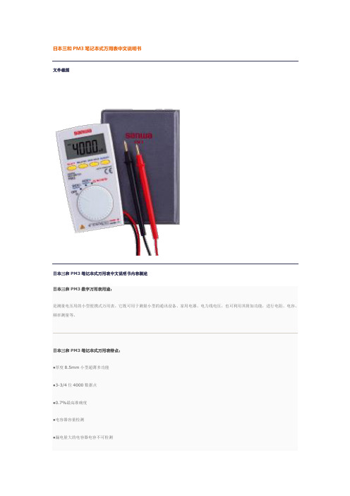
文件截图
日本三和PM3笔记本式万用表中文说明书内容概述
日本三和PM3数字万用表用途:
是测量电压用的小型便携式万用表。它既可用于测量小型的通讯设备、家用电器、电力线电压,也可利用其附加功能,进行电阻、电容、频率测量等。
日本三和PM3笔记本式万用表特点:
●厚度8.5mm小型超薄多功能
●背光及控制带LED的蜂鸣器
日本三和PM3笔记本式万用表特性:
●显示:数值4000
●抽样率:数值3次/秒
●安全规格:IEC1010 CAT. II DC/AC500V MAX.
日本三和PM3笔记本式万用表技术参数
PM3
测量量程
最高准确度
分辨率
输入电阻
直流电压
400m/4/40/400/500V
±(0.7%+3)
±(0.7%+5)
0.1Ω
占空比
0.1-99%
通断
10Ω-120Ω以下有蜂鸣音开路电压:约0.4V
二极管测试
开路电压约1.5V
频率特征
40-400HZ
内置电池
纽扣式锂电池C8*W56*D11.5mm/约85g
附件
手册型护套(C-PM3),使用说明书
0.1mv
DCV
10M-100MΩ
ACV
10M-11MΩ
交流电压
4/40/400/500V
±(2.3%+10)
0.001v
电阻
400/4K/40K/400K/4M/40MΩ
±(2.0%+5)
0.1Ω
电容器容量
4n/40n/400n/4μ/40μ/200μF
±(5.0%+10)
PM3操作说明

PM3主监控前面板图PM3主监控操作说明✧ 前面板如图所示:✧ 键功能定义: F1- F4 : 对应LCD 显示的功能,在不同状态有不同的定义。
设 置 : 在系统设置状态和系统操作状态用于改变状态设定,如:模块有无、 模块开关机、均浮充等。
清 除 : 在系统设置和系统操作状态输入数据错误时清除输入数据,以便重新输入。
“↑↓”: 在系统设置和系统操作状态改变光标位置。
确 认 : 在出现告警时用于告警确认,在系统操作状态用于下载操作数据。
复 位 : 复位系统监控,复位时不影响系统监控工作状态。
数字 键 : 在系统设置和系统操作时输入数据。
✧ 基本操作说明:系统操作采用菜单式分层结构,同时配有基本操作提示,因而操作简单、清晰、方便。
系统上电时显示公司信息和当前时间,显示界面如下,在此状态按任意键进入系统信息显示,如不按键2分钟后自动进入系统信息显示。
12:00:00深圳市汇业达通讯技术有限公司系统信息显示界面如下:该页面显示系统当前状态和合母、控母及电池的基本信息以及当前时间,按“F3”键进入主菜单显示,再按“F3”键返回公司信息显示。
合母: 0.0 V 12:00:00控母: 0.0 V 0.0 A电池: 0.0 V 0.0 A 菜单容量: 81 % 浮充返回主菜单显示如下:该页面显示系统主菜单,按数字“1”键进入信息查询菜单,按数字“2”键进入系统设置,需输入密码,输入正确可进入系统设置,错误则返回主菜单,按数字“3”键进入系统操作,需输入密码,输入正确可进入系统操作,错误则返回主菜单,按数字“4”键进入放电计量,按数字“5”键进入系统配置,需输入密码,密码正确可进入系统配置,错误则返回主菜单1. 信息查询 5. 系统配置2. 系统设置3. 系统操作返回4. 放电计量信息查询说明:信息查询菜单显示如下:该页面显示信息查询菜单,按数字键“1”进入当前信息显示,信息包括交流配电信息,直流馈电信息和模块工作信息。
PM-3 用户手册说明书

PM-3 Planar Magnetic HeadphonesUser ManualContentsImportant Safety Information ‐‐‐‐‐‐‐‐‐‐‐‐‐‐‐‐‐‐‐‐‐‐‐‐‐‐‐‐‐‐‐‐‐‐‐‐‐‐‐‐‐‐‐‐‐‐‐‐‐‐‐‐‐ 2 Introduction ‐‐‐‐‐‐‐‐‐‐‐‐‐‐‐‐‐‐‐‐‐‐‐‐‐‐‐‐‐‐‐‐‐‐‐‐‐‐‐‐‐‐‐‐‐‐‐‐‐‐‐‐‐‐‐‐‐‐‐‐‐‐‐‐‐‐‐‐‐‐‐‐‐‐‐‐ 3 Feature Highlights ‐‐‐‐‐‐‐‐‐‐‐‐‐‐‐‐‐‐‐‐‐‐‐‐‐‐‐‐‐‐‐‐‐‐‐‐‐‐‐‐‐‐‐‐‐‐‐‐‐‐‐‐‐‐‐‐‐‐‐‐‐‐‐‐‐‐‐‐ 4 Using Your Headphones ‐‐‐‐‐‐‐‐‐‐‐‐‐‐‐‐‐‐‐‐‐‐‐‐‐‐‐‐‐‐‐‐‐‐‐‐‐‐‐‐‐‐‐‐‐‐‐‐‐‐‐‐‐‐‐‐‐‐‐‐‐ 5 Specifications ‐‐‐‐‐‐‐‐‐‐‐‐‐‐‐‐‐‐‐‐‐‐‐‐‐‐‐‐‐‐‐‐‐‐‐‐‐‐‐‐‐‐‐‐‐‐‐‐‐‐‐‐‐‐‐‐‐‐‐‐‐‐‐‐‐‐‐‐‐‐‐‐‐‐‐ 7Important Safety InformationBefore using your headphones, make sure to lower the volume level on your headphone amplifier or portable device. Prolonged exposure to high volumes may result in temporary or even permanent hearing loss.Be aware of your surroundings. Using headphones may diminish your ability to hear important ambient sounds. Exercise caution particularly at railroad tracks, crosswalks, or any environment where motor vehicles or bicycles are present.It is always recommended to lower the volume level prior to connecting or disconnecting your headphones.Do not leave your headphones or cables in an area where people or pets might trip over them.Always supervise children who are using these headphones.IntroductionCongratulations! You are now the proud owner of a pair of truly portable closed‐back planar magnetic headphones.The OPPO PM‐3 utilizes a planar magnetic driver that is developed from the driver in our EISA award‐winning PM‐1 headphones. Technological breakthroughs achieved during the PM‐1’s development, such as the 7‐layer double‐side voice coil diaphragm design and FEM‐optimized neodymium magnet system, have enabled OPPO to reduce the weight of the planar magnetic drivers while maintaining excellent sound quality and high sensitivity. The PM‐3 driver’s smaller size and high sensitivity make it especially suitable for portable use, and this driver would not have been possible without the breakthroughs achieved in the PM‐1’s driver design.In the PM‐3’s planar magnetic driver, sound is generated by a very thin and light diaphragm which is driven in a symmetric pull‐push manner, and the magnetic system and conductor patterns have been optimized for maximum sensitivity and consistency. This allows the diaphragm to generate very stable and linear piston‐like vibrations, ensuring phase coherence and high resolution performance with minimal distortion. Featuring a light weight closed back design and easily driven with any smartphone or portable music player, the PM‐3 headphones will enable you to enjoy your favorite music anywhere while being isolated from outside noise.We are proud of the work we have put into these headphones, and we hope they bring you years of enjoyment.Feature Highlights∙Unique planar magnetic driver with FEM‐optimized neodymium magnet system∙7‐layer double‐side voice coil diaphragm∙Excellent sound quality∙High sensitivity and consistency∙Lightweight for portable use∙Comfortable fit for long‐term listening∙Closed‐back noise isolation design∙Selvedge denim carrying case∙Detachable high quality cable∙Optional headphone cable with inline mic and remote controlUsing Your HeadphonesTwo headphone cables have been included with your OPPO PM‐3.The 3 meter main cable terminates with a 3.5 mm connector and a screw‐on 6.35 mm adapter. It is suitable for connecting the PM‐3 to a headphone amplifier, AV receiver, or integrated amplifier. The screw‐on 6.35 mm adapter can be removed if necessary.The 1.2 meter portable cable terminates with a 3.5 mm plug. It can be used to connect the PM‐3 to a portable media player, cell phone, tablet, or other mobile device.Depending on the type of portable cable that you choose when you order the headphones, the cable may have no inline mic and remote control, or have a mic and remote control for Apple devices, or have a mic and remote control for Android devices.For the portable cable with a mic and remote control for Apple devices, the buttons work the same way as buttons on the original Apple EarPods. You can use the buttons to answer phone calls, start or stop music playback, or skip music tracks. Please refer to your Apple device’s user manual for details of these functions.For the portable cable with a mic and remote control for Android devices, the center button allows you to answer or end a call. Additional operations, such as double‐click or press‐and‐hold, may be possible depending on your mobile device. Please consult the user manual of your mobile device for details.Storing Your HeadphonesAfter each use, it is recommended that you place the headphones on a headphone stand. For carrying the headphones with you or for storage, you may remove the cable and fold the headphones flat to put in the selvedge denim carrying case.Caring for Your HeadphonesIn order to clean the headphones, we recommend using a clean, lint‐free cloth. Do not use harsh chemical cleaners or solvents. If necessary, you may lightly dampen the cloth with clean water.The ear pads are made of durable synthetic leather and are not designed to be detached by the end user. Should your headphones require service, please contact OPPO Digital or your place of purchase.SpecificationsHeadphone Specifications Model Name PM‐3Acoustic Principle Closed‐backEar Coupling CircumauralNominal Impedance 26 OhmSensitivity 102 dB in 1 mWClamping Pressure 5 NCables 3m detachable cable (3.5mm & 6.35 mm) 1.2 m detachable cable (3.5 mm)Cable Connectors Output: 3.5mm stereo jackInput: 6.35 mm stereo jack, 3.5 mm stereo jackWeight 320 g (without cable)Accessories Carrying case User ManualDriver SpecificationsDriver Type Planar MagneticDriver Size (Round) 55 mm diameterMagnet System Symmetric push‐pull neodymium Frequency Response InFree‐Field10 – 50,000 HzLong‐Term Max InputPower500 mW according to IEC 60268‐7 Pulse Max Input Power 2 WCE markThis product complies with European Low Voltage (2006/95/CE), Electromagnetic Compatibility (2004/108/EC) and Environmentally‐Friendly Design of Energy‐Related Products (2009/125/EC) Directives when used and installed according to this instruction manual.WEEE symbolCorrect Disposal of This Product. (Waste Electrical & Electronic Equipment) Applicable in the European Union and other European countries with separate collection systems.This marking on the product, accessories or literature indicates that the product and its electronic accessories should not be disposed of with other household waste at the end of their working life. To prevent possible harm to the environment or human health from uncontrolled waste disposal, please separate these items from other types of household waste and recycle them responsibly to promote the sustainable reuse of material resources.。
PMS3XXX颗粒物传感器中文说明书V2.0
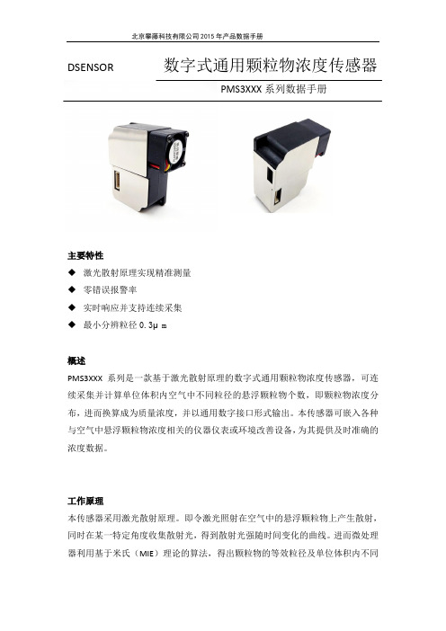
DSENSOR数字式通用颗粒物浓度传感器PMS3XXX系列数据手册主要特性◆激光散射原理实现精准测量◆零错误报警率◆实时响应并支持连续采集◆最小分辨粒径0.3μm概述PMS3XXX系列是一款基于激光散射原理的数字式通用颗粒物浓度传感器,可连续采集并计算单位体积内空气中不同粒径的悬浮颗粒物个数,即颗粒物浓度分布,进而换算成为质量浓度,并以通用数字接口形式输出。
本传感器可嵌入各种与空气中悬浮颗粒物浓度相关的仪器仪表或环境改善设备,为其提供及时准确的浓度数据。
工作原理本传感器采用激光散射原理。
即令激光照射在空气中的悬浮颗粒物上产生散射,同时在某一特定角度收集散射光,得到散射光强随时间变化的曲线。
进而微处理器利用基于米氏(MIE)理论的算法,得出颗粒物的等效粒径及单位体积内不同粒径的颗粒物数量。
传感器各功能部分框图如图1所示图1 传感器功能框图技术指标如表1所示表1 传感器技术指标数字接口定义图2 接口示意图注:产品型号后缀为P的系列有PWM输出输出结果主要输出为单位体积内各浓度颗粒物质量浓度单位为:微克/立方米。
输出分为主动输出和被动输出两种状态。
传感器上电后默认状态为主动输出,即传感器主动向主机发送串行数据,时间间隔为200~800ms,空气中颗粒物浓度越高,时间间隔越短。
主动输出又分为两种模式:平稳模式和快速模式。
在空气中颗粒物浓度变化较小时,传感器输出为平稳模式,即每三次输出同样的一组数值,实际数据更新周期约为2s。
当空气中颗粒物浓度变化较大时,传感器输出自动切换为快速模式,每次输出都是新的数值,实际数据更新周期为200~800ms。
PWM输出:PMS3XXXP系列产品带有PWM输出,PWM周期为1秒,低电平时间长度代表PM2.5浓度(大气环境下),每1ms低电平代表1ug/m³。
例如低电平时间长度为210ms,则代表此时PM2.5质量浓度值(大气环境)为210ug/m³典型电路连接图3 典型电路连接示意图电路设计应注意1.PMSXXXX需要5V供电,这是因为风机需要5V驱动。
LED-580F系列使用说明书V1.1(中文)

PMV D3定位器使用入门
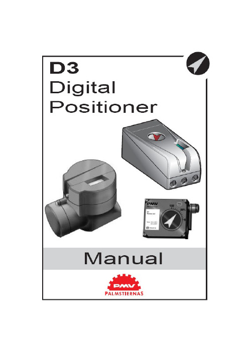
PMV D3数字阀门定位器使用手册1. 简介PMV D3是一种数字式阀门定位器,主要用于阀门调节。
单作用、双作用执行器上均可安装,也适用于直行程和角行程两种型式。
它还可以选装反馈、限位开关、压力表等部件。
这些部件是在发货之前就装配好的,交货后也可定制。
反馈和限位开关部件包括4-20mA反馈和下列三者之一——双机械触点、双簧片开关、双电感式传感器(DIN 19234)。
安全使用的特殊设计PMV D3I(本安型)的封装由铝组成,应避免应用中发生外界物体对其的任何碰撞或摩擦。
2. 存储(略)3.设计PMV D3定位器包括:·电路板,附有微处理器、HART模块、Profibus、Foundation Fieldbus(基金会现场总线)、显示,等等;·阀块;·带电位差计的位置反馈;·电气连接的密封隔离。
按钮和显示屏位于铝盖下方,由O型环密封。
下图为移去盖子后的PMV D3。
4. 不同型号的PMV D3PMV D3通用型PMV D3数字定位器极易使用,它含有五个按钮的用户接口和LCD显示屏。
通信方式有4-20mAHART、基金会现场总线和Profibus PA。
全部PMV D3定位均能可含有反馈、Fail Freeze(失效保护,当掉电时保持失效前的阀位)、270度旋转(对于外部行程)和压力计。
PMV D3 防爆型PMV D3数字定位器还可加上防爆外壳。
防爆型具备所有通用型的性能特点,也含有五个按钮的用户接口和LCD显示屏,也可以通过HART、基金会现场总线和Profibus进行通信。
但是防爆型增加了压力计接口和就地图形化LCD显示器。
ATEX:EEx d ⅡB + h2T6(Ta+65℃),T5(Ta+80℃) Ⅱ 2GDPMV D3 本安型易爆炸危险场所可使用本安型PMV D3数字定位器。
本安型具备前两种型号定位器的所有性能特点。
ATEX:EEx ia ⅡC T4 Ta=-30……80℃Ⅱ 1GDCSA, FM Class I Div.1 Grps B, C, D, Class ⅡDiv.1 Grps E, F, G, T6, T5.PMV D3 遥控安装该型适合安装于一些特殊应用场合,如振动、高(或低)温腐蚀环境、难以接近或进入场合等。
PFM3流量监测仪操作手册说明书
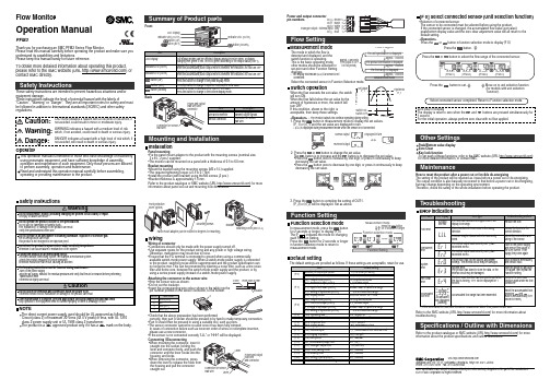
Flow MonitorOperation ManualPFM3Safety InstructionsSafety InstructionsSummary of Product partsMounting and Installationbutton (UP) button (SET)button (DOWN)Indicator LED (OUT2)Indicator LED (OUT1)LCD DisplayCAUTION indicates a hazard with a low level of risk which, if not avoided, could result in minor or moderate injury.Caution:Warning:Danger:WARNING indicates a hazard with a medium level of risk which, if not avoided, could result in death or serious injury.DANGER indicates a hazard with a high level of risk which, if not avoided, will result in death or serious injury.LCD DisplayDisplays the flow value, setting mode, and error indication.Four display modes can be selected: display always in red or green, or displaychanging from green to red, or red to green, according to the output status (OUT1).Indicator LED (OUT1)Indicates the output status of OUT1. LED is ON (Green) when OUT1 is ON.When the accumulated pulse output mode is selected, the indicator LED will turn OFF.Indicator LED (OUT2)Indicates the output status of OUT2. LED is ON (Red) when OUT2 is ON.When the accumulated pulse output mode is selected, the indicator LED will turn OFF.button (UP)Selects the mode or increases the ON/OFF set value.Press this button to change to the peak display mode.button (SET)Press this button to change to another mode and to set a value.ItemDescriptionThank you for purchasing an SMC PFM3 Series Flow Monitor.Please read this manual carefully before operating the product and make sure you understand its capabilities and limitations.Please keep this manual handy for future reference.To obtain more detailed information about operating this product,please refer to the SMC website (URL ) or contact SMC directly.These safety instructions are intended to prevent hazardous situations and/or equipment damage.These instructions indicate the level of potential hazard with the labels of"Caution", "Warning" or "Danger". They are all important notes for safety and must be followed in addition to International standards (ISO/IEC) and other safety regulations.OperatorThis operation manual is intended for those who have knowledge of machinery using pneumatic equipment, and have sufficient knowledge of assembly,operation and maintenace of such equipment. Only those persons are allowed to perform assembly, operation and maintenance.Read and understand this operation manual carefully before assembling,operating or providing maintenance to the product.Do not operate the product outside of the specifications.Do not use for flammable or harmful fluids.Fire, malfunction, or damage to the product can result.Verify the specifications before use.Do not disassemble, modify (including changing the printed circuit board) or repair.An injury or failure can result.Do not operate in an atmosphere containing flammable, explosive or corrosive gas.Fire or an explosion can result.This product is not designed to be explosion proof.Do not use the product in a place where static electricity is a problem.Otherwise it can cause failure or malfunction of the system.If using the product in an interlocking circuit:•Provide a double interlocking system, for example a mechanical system.•Check the product regularly for proper operation.Otherwise malfunction can result, causing an accident.The following instructions must be followed during maintenance :•Turn off the power supply•Stop the air supply, exhaust the residual pressure and verify that the air is released before performing maintenance workOtherwise an injury can result.After maintenance is complete, perform appropriate functional inspections and leak tests.Stop operation if the equipment does not function properly or there is a leakage of fluid.Do not touch the terminals and connectors while the power is on.Otherwise electric shock, malfunction or damage to the product can result.WarningCautionNOTEThe direct current power supply used should be UL approved as follows.Circuit (class 2) of maximum 30 Vrms (42.4 V peak) or less, with UL 1310class 2 power supply unit or UL 1585 class 2 transformer.The product is a approved product only if it has a mark on the body.button (DOWN)Selects the mode or decreases the ON/OFF set value.Press this button to change to the bottom display mode.Mounting screw (M3 x 5 L)BracketInstallationPanel mounting•Fix the panel mount adapter to the product with the mounting screws (nominal size:3 x 8 L, 2 pcs.) supplied.•The monitor can be mounted on a panel with a thickness of 0.5 to 6.0 mm.Bracket mounting•Mount the bracket using the mounting screws (M3 x 5 L) supplied.•The required tightening torque is 0.5 to 0.7 Nm.•Install the product (with bracket) using the M4 screws (2 pcs.).•Bracket thickness is approximately 1.6 mm.Refer to the product catalogue or SMC website (URL ) for more information about panel cut-out and mounting hole dimensions.<Operation>∗: The Product outputs will continue operating during setting.1. Press the button in measurement mode to display the set values.[P_1] or [n_1] and the set value are displayed in turn.∗: [LLL] is displayed during measurement mode when the sensor is not connected.2. Press the or button to change the set value.The button is to increase and the button is to decrease the set value.•Press the button once to increase by one digit, or press it continuously to keep increasing the set value.•Press the button once to decrease by one digit, or press it continuously to keep decreasing the set value.3. Press the button to complete the setting of OUT1.[P_2] or [n_2] will be displayed. Set as above.FLOW/minDisplayed in turnNormal output Reversed outputFLOW /min FLOW /minFLOW/minFlow SettingMeasurement modeThe mode in which the flow is detected and displayed, and the switch function is operating.This is the basic operating mode;other modes should be selected for set-point and other Function Setting changes.∗: The display will indicate [LLL] if a sensor is not connected.Power is suppliedapprox. 1 secondapprox. 1 secondapprox. 1 secondThe unit specification is displayedThe product identification is displayedThe flow range is displayedMeasurement mode(The output is OFF for this period)approx. 3 seconds Switch operationWhen the flow exceeds the set value, the switch will turn ON.When the flow falls below the set value by the amount of hysteresis or more, the switch will turn OFF.If this condition, shown to the right, is acceptable, then keep these settings.Switch ON Switch OFFSet value P_1Time [s]F l o w [L /m i n ]Hysteresis H_1Other SettingsPeak/Bottom value display Zero ClearKey lock functionTo set each of these functions, refer to the SMC website (URL )for more detailed information, or contact SMC.TroubleshootingError indicationFlow errorThe flow has exceeded the upper limit of the display flow range.Reduce the flow.Error nameError displayError typeTroubleshooting method Overcurrent errorThe switch output load current (OUT1) has exceeded 80 mA.The switch output load current (OUT2) has exceeded 80 mA.Turn off the power supply and remove the cause of the over current. Then supply the power again.System errorThe product has lost the factory adjustment settings. The internal circuit may be damaged.Stop operation immediately and contact SMC.Zero clear errorPerform the zero clearfunction again under no flow conditions.Accumulated flow errorAccumulated flow displayed (flashing)Accumulated flow range has been exceeded.The zero clear function has been performed while the fluid is flowing. "Er4" will be displayed for 1second.System error.The product has failed to store the data, or the internal circuit may be damaged.Turn the power off and turn it on again, then repeat the Function Setting.There is a flow of 5% or more in the wrong direction.Ensure the flow is in the correct direction.Reset the accumulated flow.(pressing andbuttons simultaneously for 1second or more)Note: Specifications are subject to change without prior notice and any obligation on the part of the manufacturer.© 2011 SMC Corporation All Rights ReservedAkihabara UDX 15F , 4-14-1, Sotokanda, Chiyoda-ku, Tokyo 101-0021, JAP AN Phone: +81 3-5207-8249 Fax: +81 3-5298-5362URL Function selection modeIn measurement mode, press the button for 2 seconds or longer, to display [F 0].The [F ] indicates the mode for changing each Function Setting.Press the button for 2 seconds or longer in function selection mode to return to measurement mode.Function SettingMeasurement modeFunction selection modeFunction SettingPress the button for 2 seconds or longerMounting screwsPanel mount adapter (can be rotated 90 degrees for mounting).Front protective cover (option)A sensor may be disconnected or incorrectly wired.Check the connection and wiring of the sensor.Power and output lead wire and connectorConnector for sensor lead wireFrontBackPower and output lead wire and connector Cable to supply power and transmit output signals.Sensor connectorConnector for sensor lead wire.ItemDescriptionAttaching the connector to the sensor wire •Strip the sensor wire as shown.•Do not cut the insulator.•Insert the corresponding wire colour shown in the table into the pin number printed on the sensor connector, to the bottom.WiringWiring of connector•Connections should only be made with the power supply turned off.•Use separate routes for the product wiring and any power or high voltage wiring.Otherwise, malfunction may result due to noise.•Ensure that the FG terminal is connected to ground when using a commerciallyavailable switch-mode power supply. When a switch-mode power supply is connected to the product, switching noise will be superimposed and the product specification can no longer be met. This can be prevented by inserting a noise filter, such as a line noise filter and ferrite core, between the switch-mode power supply and the product, or by using a series power supply instead of a switch-mode power supply.more than 20 mmCover InsulatorA12Pin no.Brown (DC+)NC Wire colour 34Blue (DC−)Black (IN (1 to 5 V))•Check that the above preparation has been performedcorrectly, then part A shown should be pressed in by hand to make temporary connection.•Part A should then be pressed in using a suitable tool, such as pliers.•The sensor connector cannot be re-used once it has been fully crimped.In cases of connection failure such as incorrect order of wires or incomplete insertion,please use a new connector.•If the sensor is not connected correctly “LLL” or “HHH” will be displayed.Connecting / Disconnecting•When mounting the connector, insert it straight into the socket, holding thelever and connector body, and push the connector until the lever hooks into the housing, and locks.•When removing the connector, press down the lever to release the hook from the housing and pull the connector straight out.Power and output lead wireand connectorConnector for sensor lead wireLeverLever1DC(-) BlueDC(+) Brown OUT1 BlackOUT2 WhiteAnalogue output / External input Grey2345Power and output connector pin numbers [F 0] Select connected sensor (Unit selection function)•Selection of connected sensorThe sensor to be connected must be selected before using the product.If the connected sensor is changed, the accumulated flow value (set value),peak/bottom display value and the zero clear adjustment value will all return to the default setting.Press the or button to select the flow range of the connected sensor.10 L/min (PFM510)25 L/min (PFM525)50 L/min (PFM550)100 L/min (PFM511)Press thebutton to set.Move on to unit selection function (for models with unit selection function).Select connected sensor completed. Return to Function selection mode.Default settingThe default settings are provided as follows. If these settings are acceptable, retain for use.Item[oU1] Output mode (OUT1)[1ot ] Reversed output (OUT1)[H_1] Setting of hysteresis (OUT1)[CoL] Display colour Default setting[HYS ] Hysteresis mode [1_P ] Normal output[3] 3% of rated flow range[SoG ] ON: Green OFF: Red [oU2] Output mode (OUT2)[2ot ] Reversed output (OUT2)[P_2] Input of set value (OUT2)[H_2] Setting of hysteresis (OUT2)[HYS ] Hysteresis mode [2_P ] Normal outputMedium value of rated flow range [3] 3% of rated flow range [FLU] Operating fluid [r EF] Reference condition [A ir ] dry air, N 2[Anr .] Standard condition [P_1] Input of set value (OUT1)Medium value of rated flow range [eES] Response time [dSP] Display mode [1.00] 1 second[ inS] Instantaneous flow[Un i ]Unit selection function [ L] L/minSelection of connected sensor [10] 10 L/min (PFM510)[F 0][F 1][F 2][F 3][F 4][F 5][F 6][F 7][F 8][F 9][F10][F11][F12][F13][F98][F99][ inP ] External input [ r_r ] Accumulated flow external reset [dr E] Display resolution [PrS] Auto-preset[1E2] 100-split [oFF] Manual [EEP ] Accumulated value hold [AFL] Analogue output filter [oFF] OFF [on ] With filter [Eco ] Power saving mode [oFF] Unused [P in] Security code [ALL] Setting of all functions [oFF] Unused [oFF] Unused [ in i ] Reset to the default settings[oFF] Unused∗: If the error cannot be reset after the above measures are taken, then please contact SMC.Specifications / Outline with DimensionsRefer to the product catalogue or SMC website (URL ) for more information about the product specifications and outline dimensions.Refer to the SMC website (URL ) for more information about troubleshooting.Select the connected sensor in Function Selection mode.Zero clear of DisplayThe display is reset to zero when the and buttons are pressed simultaneously for 1 second.For the initial operation, always perform zero clear with no flow applied.MaintenanceHow to reset the product after a power cut or forcible de-energizingThe setting of the product will be retained as it was before a power cut or de-energizing.The output condition is also basically recovered to that before a power cut or de-energizing,but may change depending on the operating environment.Therefore, check the safety of the whole installation before operating the product.<Operation>Press the orbutton in function selection mode to display [F 0].Press thebutton.。
PM3--使用教程

PM3 操作
设备连接示意图:
-------------------------------
设备连接电脑之后,设备管理器可以查看
打开PM3
查看电压命令:hw tu
读卡号命令:hf 14a read
(方上卡片)位置正确的话可以正常读出卡号。
读不出可以移动卡的位置
如果已经确定是全加密卡。
直接爆破命令:
hf mf mifare
卡片连接天线正确的话,命令行会出现数据窗口。
同时电路板的蓝色灯闪烁。
成功爆破密码:
破解全部扇区的密码,并且保存密码文件
命令:hf mf nested 1 0 a 密码 d
密码出来之后。
如果出现00000000的情况,可以在爆破1次。
(先保存好得到的密码文件.然后手动把密码加进去)
密码文件可以用 16进制软件查看。
(密码排列顺序。
先是全部A密码然后全部B密码)
生成dump文件,一定要先手动替换掉0000的数据
(也就是 FFFFFFFFF)
生成DUMP 命令。
hf mf dump
会在同目录生成 dumpdata.bin 这个文件.
这个就是 dump文件。
可以直接修改文件后缀
.bin 为 .dump。
- 1、下载文档前请自行甄别文档内容的完整性,平台不提供额外的编辑、内容补充、找答案等附加服务。
- 2、"仅部分预览"的文档,不可在线预览部分如存在完整性等问题,可反馈申请退款(可完整预览的文档不适用该条件!)。
- 3、如文档侵犯您的权益,请联系客服反馈,我们会尽快为您处理(人工客服工作时间:9:00-18:30)。
在使用一下操作之前,先将PM3固件换成离线侦测固件
1.使用命令行进行离线嗅探准备工作
a)准备移动电源一只,双口USB一根,副口接入移动电源,Mini口接入设备,设
备可正常供电;
b)主口接入电脑USB接口,在电脑上可以识别到PM3设备;
2.嗅探指令发出
a)打开\PM3发布资料\官方软件固件\pm3-bin-2.0.0\win32(client+GUI)下PM3指令
台.bat
b)在终端输入hf14a snoop(此时,设备的黄色灯亮起[A灯亮])
c)然后关闭PM3指令台;
3.拔出连接电脑的主口,移动电源保持通电,将PM3高频天线放置读卡机之上,让读卡
机正常读卡。
(如果Reader正常工作,Proxmark3就能监听到正常通信数据,此时绿色(LED_B)灯亮。
保持嗅探状态多读取几次,板子上红色(LED_C)灯与绿色(LED_B)灯会交替变亮,等到绿(LED_B)、黄(LED_A)灯都是亮的状态时可以停止嗅探。
)
4.移动电源保持通电,将USB线主口重新接入电脑,按下板子上的按钮。
(短按一下就OK
了。
)此时板子上的LED灯都灭掉。
等待3~5秒,待USB重新加载后,进入打开PM3指令台,输入hf list14a
5.找到60或者61开头的数据
a)60代表使用的是A密码,
b)61代表使用的是B密码,
c)后面一个数据03是十六进制的块区号,这里03代表读取的是第3块,即0扇区。
d)那么这里计算出的密码将是0扇区A密码
6.计算密码
a)找到UID号,可以通过中文软件读出卡的UID号。
找到60或者61开头的数据,
然后打开crapto1gui【嗅探卡片和读卡机解密】.exe,填入对应的数据,如图所示
b)计算出秘钥
7.对比秘钥,用中文软件进行破解,可以发现PRNG找到的秘钥与计算出的秘钥一致。
(演示所使用的卡是可以被直接破解的,实际使用的卡是不能被直接破解,所以破解全卡看第八步)
8.破解全卡
a)打开中文软件,点击知一密求全密,输入对应的扇区号,密码,密码类型
b)解出全秘钥c)。