MCH0805KDS中文资料
Vishay BCcomponents 0805型号多层抗谱电阻说明书

MLV0805E30403T MLV0805E32503TMLV0805E3Vishay BCcomponentsSMD 0805 Multilayer VaristorFEATURES•Surface mount multilayer surge suppressor •Inherent bidirectional clamping •Excellent energy / volume ratio •Suitable for reflow soldering•Material categorization:for definitions of compliance please see /doc?99912APPLICATIONSOver-voltage and transient voltage protection:•Data lines and I/O port protection •Protection against ESD transients•On-board protection of IC’s and transistors •Modem protection •LCD protectionDESCRIPTIONSize 0805 (2012M) multilayer chip varistor with NiSn terminations.PACKAGINGAvailable in 8 mm paper tape, component pitch 4 mm on 180 mm reels containing 4000 pieces.Notes•Sinusoidal voltage assumed as normal operating condition.If a non-sinusoidal voltage is present, the crest voltage x 0.707 should be used for type selection •Breakdown voltage at a current of 1 mA, measured according to 4.5 of IEC 61051-1•Parts are not recommended for automotive applicationsQUICK REFERENCE DATAPARAMETERVALUEUNITMaximum continuous voltage DC 5.6 to 38.0V AC4.0 to 30.0V Maximum clamping voltage at 1 A15.5 to 77V Capacitance range (at 1 MHz)80 to 860pF Maximum energy (10/1000 μs)0.1 to 0.3J Maximum peak current 30 to 100A Operating temperature range -55 to 125°C Weight± 0.011gELECTRICAL DATA AND ORDERING INFORMATIONWORKING VOLTAGE BREAKDOWN VOLTAGEMAXIMUM CLAMPING VOLTAGEMAXIMUM PEAK CURRENTMAXIMUM ENERGYTYPICAL CAPACITANCEPART NUMBER V RMS V DC V b V C I P E M C SAP V V V V A J pF MLV0805E31 mA 1 A, 8/20 μs8/20 μs 10/1000 μs1 MHz 4.0 5.67.1 to 9.315.5400.18600403T 7.09.011.0 to 14.020.0400.15850703T 11.014.016.5 to 20.330.0400.12801103T 13.018.023.0 to 28.042.01000.35501305T 25.030.037.0 to 46.065.0300.1802503T 30.038.042.3 to 51.777.0800.32203005TMLV0805E3Vishay BCcomponentsDIMENSIONS in millimetersRECOMMENDED FOOTPRINT in millimetersV/I CHARACTERISTICSL 1W T L 2and L 32.0 ± 0.21.25 ± 0.21.1 max.0.4 ± 0.3CA B C 1.41.23.410-510-410-310-210-1110102110100V o l t a g e (V )Current (A)Legal Disclaimer Notice VishayDisclaimerALL PRODUCT, PRODUCT SPECIFICATIONS AND DATA ARE SUBJECT TO CHANGE WITHOUT NOTICE TO IMPROV E RELIABILITY, FUNCTION OR DESIGN OR OTHERWISE.V ishay Intertechnology, Inc., its affiliates, agents, and employees, and all persons acting on its or their behalf (collectively,“Vishay”), disclaim any and all liability for any errors, inaccuracies or incompleteness contained in any datasheet or in any other disclosure relating to any product.Vishay makes no warranty, representation or guarantee regarding the suitability of the products for any particular purpose or the continuing production of any product. To the maximum extent permitted by applicable law, Vishay disclaims (i) any and all liability arising out of the application or use of any product, (ii) any and all liability, including without limitation special, consequential or incidental damages, and (iii) any and all implied warranties, including warranties of fitness for particular purpose, non-infringement and merchantability.Statements regarding the suitability of products for certain types of applications are based on Vishay's knowledge of typical requirements that are often placed on Vishay products in generic applications. Such statements are not binding statements about the suitability of products for a particular application. It is the customer's responsibility to validate that a particular product with the properties described in the product specification is suitable for use in a particular application. Parameters provided in datasheets and / or specifications may vary in different applications and performance may vary over time. All operating parameters, including typical parameters, must be validated for each customer application by the customer's technical experts. Product specifications do not expand or otherwise modify Vishay's terms and conditions of purchase, including but not limited to the warranty expressed therein.Hyperlinks included in this datasheet may direct users to third-party websites. These links are provided as a convenience and for informational purposes only. Inclusion of these hyperlinks does not constitute an endorsement or an approval by Vishay of any of the products, services or opinions of the corporation, organization or individual associated with the third-party website. Vishay disclaims any and all liability and bears no responsibility for the accuracy, legality or content of the third-party website or for that of subsequent links.Except as expressly indicated in writing, Vishay products are not designed for use in medical, life-saving, or life-sustaining applications or for any other application in which the failure of the Vishay product could result in personal injury or death. Customers using or selling Vishay products not expressly indicated for use in such applications do so at their own risk. Please contact authorized Vishay personnel to obtain written terms and conditions regarding products designed for such applications. No license, express or implied, by estoppel or otherwise, to any intellectual property rights is granted by this document or by any conduct of Vishay. Product names and markings noted herein may be trademarks of their respective owners.© 2022 VISHAY INTERTECHNOLOGY, INC. ALL RIGHTS RESERVEDMLV0805E30403T MLV0805E32503T。
M80C85资料
GENRAL DESCRIPTIONThe MSM80C85AH is a complete 8-bit parallel; central processor implemented in silicon gate C-MOS technology and compatible with MSM80C85A.It is designed with higher processing speed (max.5 MHz) and lower power consumption compared with MSM80C85A and power down mode is provided, thereby offering a high level of system integration.The MSM80C85AH uses a multiplexed address/data bus. The address is split between the 8-bit address bus and the 8-bit data bus. The on-chip address latch : of a MSM81C55-5 memory product allows a direct interface with the MSM80C85AH.FEATURES•Power down mode (HALT-HOLD)•Low Power Dissipation: 50mW(Typ)•Single + 3 to + 6 V Power Supply•–40 to + 85°C, Operating Temperature •Compatible with MSM80C85A •0.8 m s instruction Cycle (V CC = 5V)•On-Chip Clock Generator (with External Crystal)•On-Chip System Controller; Advanced Cycle Status Information Available for Large System Control•Bug operation in MSM80C85AH is fixed•Four Vectored interrupt (One is non-maskable) Plus the 8080A-compatible interrupt.•Serial, In/Serial Out Port•Decimal, Binary and Double Precision Arithmetic •Addressing Capability to 64K Bytes of Memory •TTL Compatible•40-pin Plastic DIP(DIP40-P-600-2.54): (Product name: MSM80C85AHRS)•44-pin Plastic QFJ(QFJ44-P-S650-1.27): (Product name: MSM80C85AHJS)•44-pin Plastic QFP(QFP44-P-910-0.80-2K): (Product name: MSM80C85AHGS-2K)MSM80C85AHRS/GS/JS8-Bit CMOS MICROPROCESSORE2O0009-27-X2元器件交易网FUNCTIONAL BLOCK DIAGRAMINTR INTA 5.5 6.57.5TRAP SID SODRSTX1X2CLK OUT READY RD WR ALE S0S1IO / M HOLD HLDA RESET IN RESET OUT A15 - A8Address BusAD7- ADAddress/Data BusPIN CONFIGURATION (TOP VIEW)40 pin Plastic DIPA 8HOLD HLDA CLK(OUT)RESET IN READY IO/M S 1RD WR ALE S 0A 15A 14A 13A 12A 11A 10A 9V CC 39383736353433READY IO/M S 1RD WR NC ALE TRAP RST7.5RST6.5RST5.5INTR NC INTA 18192021222324A D 4N C A D 5A D 6A D 7G N D A 865432144S I DS O DR E S E T X 2X 1N C7891011121332313029S 0A 15A 14AD 0AD 1AD 2AD 314151617A 13V C C25262728A 9A 10A 11A 1243424140H O L D H L D AC L K (O R E S E T I NTRAP RST7.5RST6.5RST5.5INTR INTA AD 0A D 4A D 5A D 6A D 7G N D V C C A 8AD 1AD 2AD 3NC A 9A 10A 11N CMSM80C85AH FUNCTIONAL PIN DEFINITIONThe following describes the function of each pin:A 0 - A 7(Input/Output)3-state A 8 - A 15(Output, 3-state)Multiplexed Address/Data Bus: Lower 8-bits of the memory address (or I/O address) appear on the bus during the first clock cycle (T state) of a machine cycle. It then becomes the data bus during the second and third clock cycles.Address Bus: The most significant 8-bits of the memory address or the 8-bits of the I/O address, 3-stated during Hold and Halt modes and during RESET.Symbol FunctionALE (Output)Address Latch Enable: It occurs during the first clock state of a machine cycle and enables address to get latched into the on-chip latch peripherals. The falling edge of ALE is set to guarantee setup and hold times for the address information. The falling edge ALE can also be used to strobe the status information ALE is never 3-state.S 0 , S 1 , IO/M (Output)Machine cycle status:IO/M S 1 S 0 States S 1 can be used as an advanced R/W status. IO/M , S 0 and S 1 become valid at the beginning ofa machine cycle and remain stable throughout the cycle. The falling edge of ALE may be used to latch the state of these lines.RD(Output, 3-state)READ control: A low level on RD indicates the selected memory or I/O device is to be read thatthe Data Bus is available for the data transfer, 3-stated during Hold and Halt modes and during RESET.WR(Output, 3-state)WRITE control: A low level on WR indicates the data on the Data Bus is to be written into the selected memory or I/O location. Data is set up at the trailing edge of WR , 3-stated during Hold and Halt modes and during RESET.READY (Input)If READY is high during a read or write cycle, it indicates that the memory or peripheral is ready to send or receive data. If READY is low, the cpu will wait an integral number of clock cycles for READY to go high before completing the read or write cycle READY must conform to specified setup and hold times.HOLD (Input)HLDA (Output)HOLD ACKNOWLEDGE: Indicates that the cpu has received the HOLD request and that it will relinquish the bus in the next clock cycle. HLDA goes low after the Hold request is removed. The cpu takes the bus one half clock cycle after HLDA goes low.HOLD indicates that another master is requesting the use of the address and data buses.The cpu, upon receiving the hold request, will relinquish the use of the bus as soon as the completion of the current bus transfer. Internal processing can continue. The processor can regain the bus only after the HOLD is removed. When the HOLD is acknowledged, the Address, Data, RD , WR , and IO/M lines are 3-stated. And status of power down is controlled by HOLD.INTR (Output)INTERRUPT REQUEST: Is used as a general purpose interrupt. It is sampled on during the next to the last clock cycle of an instruction and during Hold and Halt states. If it is active, the Program Counter (PC) will be inhibited from incrementing and an INTA will be issued. During this cycle a RESTART or CALL instruction can be inserted to jump to the interrupt service routine. The INTR is enabled and disabled by software. It is disabled by Reset and immediately after an interrupt is accepted. Power down mode is reset by INTR.INTA (Output)INTERRUPT ACKNOWLEDGE: Is used instead of (and has the same timing as) RD during the instruction cycle after an INTR is accepted.RST 5.5RST 6.5RST 7.5(Input)RESTART INTERRUPTS: These three inputs have the same timing as INTR except they cause an internal RESTART to be automatically inserted.The priority of these interrupts is ordered as shown in Table 1. These interrupts have a higher priority than INTR. In addition, they may be individually masked out using the SIM instruction. Power down mode is reset by these interrupts.TRAP (Input)Trap interrupt is a nonmaskable RESTART interrupt. It is recognized at the same timing as INTR or RST 5.5 - 7.5. It is unaffected by any mask or Interrupt Disable. It has the highest priority of any interrupt. (See Table 1.) Power down mode is reset by input of TRAP.001100101110101Memory write Memory read I/O write I/O readOpcode fetchIO/M S 1 S 0 States 1...10¥¥10¥¥Interrupt Acknowledge Halt = 3-stateHold (high impedance)Reset ¥ = unspecifiedName Address Branched To (1)When Interrupt OccursType TriggerRST 7.53CH 34H Rising edge (latched).High level unitl sampled.RST 6.5RST 5.52CH (2)High level until sampled.High level until sampled.INTRTRAP Priority 2345124H Rising edge and high level unit sampled.Table 1 Interrupt Priority, Restart Address, and SensitivityNotes:(1)The processor pushes the PC on the stack before branching to the indicatedaddress.(2)The address branched to depends on the instruction provided to the cpuwhen the interrupt is acknowledged.RESET IN (Input)Sets the Program Counter to zero and resets the Interrupt Enable and HLDA flip-flops and release power down mode. The data and address buses and the control lines are 3-stated during RESET and because of the asynchronous nature of RESET IN, the processor's internal registers and flags may be altered by RESET with unpredictable results. RESET IN is a Schmitt-triggered input, allowing connection to an R-C network for power-on RESET delay. The cpu is held in the reset condition as long as RESET IN is applied.Symbol FunctionRESET OUT (Output)Indicated cpu is being reset. Can be used as a system reset. The signal is synchronized to the processor clock and lasts an integral number of clock periods.X 1, X 2(Input)X 1 and X 2 are connected to a crystal to drive the internal clock generator. X 1 can also be an external clock input from a logic gate. The input frequency is divided by 2 to give the processor's internal operating frequency.SID (Input)Serial input data line. The data on this line is loaded into accumulator bit 7 whenever a RIM instruction is executed.SOD (Output)Serial output data line. The output SOD is set or reset as specified by the SIM instruction.V CC + 5 Volt supply GNDGround Reference.CLK (Output)Clock Output for use as a system clock. The period of CLK is twice the X 1, X 2 input period.FUNCTIONAL DESCRIPTIONThe MSM80C85AH is a complete 8-bit parallel central processor. It is designed with silicon gate C-MOS technology and requires a single +5 volt supply. Its basic clock speed is 5 MHz, thus improving on the present MSM80C85A's performance with higher system speed and power down mode. Also it is designed to fit into a minimum system of two IC's: The CPU (MSM80C85AH), and a RAM/IO (MSM81C55-5)The MSM80C85AH has twelve addressable 8-bit register pairs. Six others can be used interchangeably as 8-bit registers or 16-bit register pairs. The MSM80C85AH register set is as follows:PC 16-bit address 8-bit ¥ 6 or 16-bits ¥ 3BC, DE, HL SP 16-bit address 5 flags (8-bit space)Flags or FProgram CounterACC or A 8-bits Accumulator Mnemonic ContentsRegisterGeneral-Purpose Registers; data pointer (HL)Stack Pointer Flag RegisterThe MSM80C85AH uses a multiplexed Data Bus. The address is spilt between the higher 8-bit Address Bus and the lower 8-bit Address/Data Bus. During the first T state (clock cycle) of a machine cycle the low order address is sent out on the Address/Data Bus. These lower 8-bits may be latched externally by the Address Latch Enable signal (ALE). During the rest of the machine cycle the data bus is used for mamory or I/O data.The MSM80C85AH provides RD , WR , S 0, S 1, and IO/M signals for bus control. An Interrupt Acknowledge signal (INTA ) is also provided. Hold and all Interrupts are synchronized with the processor's internal clock. The MSM80C85AH also provides Serial Input Data (SID) and Serial Output Data (SOD) lines for a simple serial interface.In addition to these features, the MSM80C85AH has three maskable, vector interrupt pins, one nonmaskable TRAP interrupt and power down mode with HALT and HOLD.INTERRUPT AND SERIAL I/OThe MSM80C85AH has 5 interrupt inputs: INTR, RST 5.5 RST 6.5, RST 7.5, and TRAP. INTR is identical in function to the 8080A INT. Each of the three RESTART inputs, 5.5, 6.5, and 7.5, has a programmable mask. TRAP is also a RESTART interrupt but it is nonmaskable.The three maskable interrupts cause the internal execution of RESTART ( saving the program counter in the stack branching to the RESTART address) it the interrupts are enable and if the interrupt mask is not set. The nonmaskable TRAP causes the internal execution of a RESTART vector independent of the state of the interrupt enable or masks. (See Table 1.)There are two different types of inputs in the restart interrupt. RST 5.5 and RST 6.5 are high level-sensitive like INTR (and INT on the 8080A) and are recognized with the same timing as INTR. RST 7.5 is rising edge-sensitive.For RST 7.5, only a pulse is required to set an internal flip-flop which generates the internal interrupt request. The RST 7.5 request flip-flop remains set until the request is serviced. Then it is reset automatically, This flip-flop may also be reset by using the SIM instruction or by issuing a RESET␣IN to the MSM80C85AH. The RST 7.5 internal flip-flop will be set by a pulse on the RST 7.5 pin even when the RST 7.5 interrupt is masked out.The interrupts are arranged in a flixed priority that determines which interrupt is to be recognized if more than one is pending, as follows: TRAP-highest priority, RST 7.5, RST 6.5, RST 5.5, INTR-lowest priority. This priority scheme does not take into account the priority of a routine that was started by a higher priority interrupt. RST 5.5 can interrupt an RST 7.5 routine if the interrupt are re-enabled before the end of the RST 7.5 routine.The TRAP interrupt is useful for catastrophic evens such as power failure or bus error. The TRAP input is recognized just as any other interrupt but has the highest priority. It is not affected by any flag or mask. The TRAP input is both edge and level sensitive. The TRAP input must go high and remain high until it is acknowledged. It will not be recognized again until it goes low, then high again. This avoids any false triggering due to noise or logic glitches. Figure 3 illustrates the TRAP interrupt request circuitry within the MSM80C85AH. Note that the servicing of any interrupt (TRAP, RST 7.5, RST 6.5, RST 5.5,INTR) disables all future interrupts (except TRAPs) until an El instruction is executed.The TRAP interrupt is special in that it disables interrupts, but preserves the previous interrupt enable status. Performing the first RIM instruction following a TRAP interrupt allows you to determine whether interrupts were enabled or disabled prior to the TRAP. All subsequent RIM instructions provide current interrupt enable status. Performing a RIM instruction following INTR or RST 5.5-7.5 will provide current interrupt Enable status, revealing that Interrupts are disabled.The serial I/O system is also controlled by the RIM and SIM instructions. SID is read by RIM, and SIM sets the SOD data.AcknowledgeFigure 3 Trap and RESET IN CircuitDRIVING THE X 1 AND X 2 INPUTSYou may drive the clock inputs of the MSM80C85AH with a crystal, or an external clock source.The driving frequency must be at least 1 MHz, and must be twice the desired internal clock frequency; hence, the MSM80C85AH is operated with a 6 MHz crystal (for 3 MHz clock). If a crystal is used, it must have the following characteristics:Parallel resonance at twice the clock frequency desired C L (load capacitance) £ 30 pF C S (shunt capacitance) £ 7 pFR S (equivalent shunt resistance) £ 75 ohms Drive level: 10 mWFrequency tolerance: ±0.05% (suggested)Note the use of the capacitors between X 1, X 2 and ground. These capacitors are required to assure oscillator startup at the correct frequency.Figure 4 shows the recommended clock driver circuits. Note in B that a pull-up resistor is required to assure that the high level voltage of the input is at least 4 V.For driving frequencies up to and including 6 MHz you may supply the driving signal to X, and leave X 2 open-circuited (Figure 4B). To prevent self-oscillation of the MSM80C85AH, be sure that X 2 is not coupled back to X 1 through the driving circuit.Note:Since the constant values may vary depending on oscillator, consult the manufacturer of the oscillator used when designing a circuit.Figure 4 Clock Driver Circuits* X 2 Left Floating33 pF Capacitor required for crystal frequency 10 to 6.25 MHz 50 pF Capacitor required for crystal frequency 6.25 to 4 MHz 100 pF Capacitor required for crystal frequency <4 MHzA. Quartz Crystal Clock DriverB. 1 - 10 MHz Input Frequency External Clock Drive CircuitBASIC SYSTEM TIMINGThe MSM80C85AH has a multiplexed Data Bus. ALE is used as a strobe to sample the lower 8-bits of address on the Data Bus. Figure 5 shows an instruction fetch, memory read and I/O write cycle (as would occur during processing of the OUT instruction). Note that during the I/ O write and read cycle that the I/O port address is copied on both the upper and lower half of the address.There are seven possible types of machine cycles. Which of these seven takes place is defined by the status of the three status lines (IO/M, S1, S0) and the three control signals (RD, WR,and INTA). (See Table 2.) The status line can be used as advanced controls (for device selection, for example), since they become active at the T1 state, at the outset of each machine cycle. Control lines RD and WR become active later, at the time when the transfer of data is to take place, so are used as command lines.A machine cycle normally consists of three T states, with the exception of OPCODE FETCH, which normally has either four or six T states (unless WAIT or HOLD states are forced by the receipt of READY or HOLD inputs). Any T state must be one of ten possible states, shown in Table 3.Table 2 MSM80C85AH Machine Cycle ChartTable 3 MSM80C85AH Machine State Chart0= Logic "0"1= Logic "1"TS = High Impedance ¥= UnspecifiedNotes:(1) ALE not generated during 2nd and 3rd machine cycles of DAD instruction.(2) IO/M = 1 during T 4 - T 6 of INA machine cycle.A AD IO/Figure 5 MSM80C85AH Basic System TimingPOWER DOWN ModeThe MSM80C85AH is compatible with the MSM80C85A in function and POWER DOWN mode. This reduces power consumption further.There are two methods available for starting this POWER DOWN mode. One is through software control by using the HALT command and the other is under hardware control by using the pin HOLD. This mode is released by the HOLD, RESET, and interrupt pins (TRAP, RST7.5, RST6.5 RST5.5, or INTR). (See Table 4.)Since the sequence of HALT, HOLD, RESET, and INTERRUPT is compatible with MSM80C85A, every the POWER DOWN mode can be used with no special attention.Start by means of Halt command Start by means of HOLD pin Released by using pins RESET and INTERRUPT (not by pin HOLD) Released by using RESET and HOLD pins (not by interrupt pins)Table 4 POWER DOWN Mode Releasing Method(1) Start by means of HALT command (See Figures 6 and 7.)The POWER DOWN mode can be started by executing the HALT command.At this time, the system is put into the HOLD status and therefore the POWER DOWN mode cannot be released even when the HOLD is released later.In this case, the POWER DOWN mode can be released by means of the RESET or interrupt.(2) Start by means of HOLD pin (See Figure 8.)During the execution of commands other than the HALT, the POWER DOWN mode is started when the system is put into HOLD status by means of the HOLD pin.Since no interrupt works during the execution of the HOLD, the POWER DOWN mode cannot be released by means of interrupt pins. In this case, the POWER DOWN mode can be released either by means of the RESET pin or by releasing the HOLD status by means of HOLD pin.CLK (OUT)ALEAD 0-7CPU MODE RESET INFigure 6 Started by HALT and Released by RESET INCLK (OUT)ALEHOLD CPU MODEHLDAFigure 8 Started and Released by HOLDCLK (OUT)ALECPU MODERST5.5Figure 7 Started by HALT and Released by RST5.5ABSOLUTE MAXIMUM RATINGS–55 - +150MSM80C85AHRS Power Supply Voltage V CC –0.5 - 7V Input Voltage V IN –0.5 - V CC +0.5V Output Voltage V OUT –0.5 - V CC +0.5V Storage Temperature T STG °CPower DissipationP D0.7WParameter Units Symbol With respect to GND—Ta = 25°CCondition LimitsMSM80C85AHGS MSM80C85AHJS1.01.0OPERATING RANGELimits Power Supply Voltage V CC 3 - 6V Operating TemperatureT OP–40 - +85°CParameterUnit Symbol RECOMMENDED OPERATING CONDITIONSDC CHARACTERISTICS"L"V ILR —–0.3+0.8Typ.Power Supply Voltage V CC 5V T OP +25"L" Input Voltage V IL —"H" Output Voltage V IH —Min.4.5–40–0.32.2Max.5.5+85+0.8V CC +0.3ParameterUnit Symbol °C V V Operating Temperature V V IHR—3.0V CC +0.3VRESET IN Input Voltage "H"RESET IN Input VoltageTyp.Max."L" Output Voltage V OL —0.4V "H" Output Voltage V OH ——V ——V Parameter Unit Symbol Min.—3.0V CC - 0.4I OL = 2.5 mA I OH = –2.5 mA I OH = –100 m A ConditionsV CC = 4.5 V - 5.5 V Ta = –40°C - +85°C Input Leak Current I LI —10m A Output Leak CurrentI LO—10m A –10–100 £ V IN £ V CC 0 £ V OUT £ V CC T cyc = 200 ns C L = 0 pF at reset Operating SupplyCurrentI CC1020mA 510mA——T cyc = 200 nsC L = 0 pF at power down modeAC CHARACTERISTICSParameter Symbol Condition Min.Max.UnitCLY Cycle Period t CYCt CYC=200 nsCL=150 pF 2002000nsCLY Low Time t140—ns CLY High Time t270—ns CLY Rise and Fall Time t r, t f—30nsX1 Rising to CLK Rising t XKR25120nsX1 Rising to CKK Falling t XKF30150nsA8~15 Valid to Leading Edge of Control (1)t AC115—ns AD0~7 Valid to Leading Edge of Control t ACL115—ns AD0~15 Valid Data in t AD—350ns Address Float After Leading Edge of RD INTA t AFR—0nsA8~15 Valid Before Trailing Edge of ALE (1)t AL50—ns AD0~7 Valid Before Trailing Edge of ALE t ALL50—ns READY Valid from Address Valid t ARY—100ns Address (A8~15) Valid After Control t CA60—ns Width of Control Law (RD, WR, INTA)t CC230—ns Trailing Edge of Control to Leading Edges of ALE t CL25—ns Data Valid to Trailing Edge of WR t DW230—ns HLDA to Bus Enable t HABE—150ns Bus Float After HLDA t HABF—150ns HLDA Valid to Trailing Edge of CLK t HACK40—ns HOLD Hold Time t HDH0—ns HOLD Step Up Time to Trailing Edge of CLK t HDS120—ns INTR Hold Time t INH0—ns INTR, RST and TRAP Setup Time to Falling Edge of CLK t INS150—ns Address Hold Time After ALE t LA50—ns Trailing Edge of ALE to Leading Edge of Control t LC60—ns ALE Low During CLK High t LCK50—ns ALE to Valid Data During Read t LDR—270ns ALE to Valid Data During Write t LDW—140ns ALE Width t LL80—ns ALE to READY Stable t LRY—30ns Trailing Edge of RD to Re-enabling of Address t RAE90—ns RD (or INTA) to Valid Data t RD—150ns Control Trailing Edge to Leading Edge of Next Control t RV220—ns Data Hold Time After RD INTA (7)t RDH0—ns READY Hold Time t RYH0—ns READY Setup Time to Leading Edge of CLK t RYS100—ns Data Valid After Trailing Edge of WR t WD60—ns LEADING Edge of WR to Data Vaild t WDL—20ns(Ta = –40°C ~ 85°C, V CC = 4.5 V ~ 5.5 V)Notes:(1)A 8 - A 15 address Specs apply to IO/M , S 0 and S 1.(2)Test condition: t CYC =200 ns C L =150 pF(3)For all output timing where C L =150 pF use the following correction factors:25 pF £ C L < 150 pF : –0.10ns/pF 150 pF < C L £ 200 pF : +0.30ns/pF(4)Output timings are measured with purely capacitive load.(5)All timings are measured to output voltage V L =0.8 V, V H =2.2 V, and 1.5 Vwith 10 ns rise and fall time on inputs.(6)To calculate timing specifications at other values of t CYC use Table 7.(7)Data hold time is guaranteed under all loading conditions.2.40.45Input Waveform for A.C. Tests:(1/2)T - 50t AL Min (Ta = -40°C - +85°C, V CC = 4.5 V - 5.5 V, C L = 150 pF)(1/2)T - 50t LA Min (1/2)T - 20t LL Min (1/2)T - 50t LCK Min (1/2)T - 40t LC Min (5/2+N)T - 150t AD Max (3/2+N)T - 150t RD Max (1/2)T - 10t RAE Min (1/2)T - 40t CA Min (3/2+N)T -70t DW Min (1/2)T - 40t WD Min (3/2+N)T - 70t CC Min (1/2)T - 75t CL Min (3/2)T - 200t ARY Max (1/2)T - 60t HACK Min (1/2)T + 50t HABF Max (1/2)T + 50(2/2)T - 85t HABE Max t AC Min (1/2)T - 60t 1Min (1/2)T - 30t 2Min (3/2)T - 80t RV Min t LDRMax——————————————————————MSM80C85AH Table 7 Bus Timing Specification as a T CYC DependentNote:N is equal to the total WAIT states.T = t CYC(2+N)T -130X1 INPUTCLKOUTPUTFigure 6 Clock Timing Waveform READ OPERATIONCLKA8-A15 AD0-AD7ALE RD / INTA T1T2T3T1WRITE OPERATIONCLK T1A8-A15AD0-AD7ALEWRT2T3T1CLKA 8~A 15AD 0~AD 7ALERD / INTAREADYT 1T 2T WAIT T 3T 1Note: READY must remain stable during setup and hold times.Figure 7 MSM80C85AH Bus Timing, With and Without WaitRead operation with Wait Cycle (Typical)–same READY timing applies to WRITE operationCLK HOLDHLDA BUSFigure 8 MSM80C85AH Hold TimingHOLD OPERATIONNOTE: (1) IO/M is also floating during this time.Figure 9 MSM80C85AH Interrupt and Hold TimingMOVE, LOAD, AND STORE MOVr1 r2MOV M r MOV r M MVI r MVI M LXI B LXI D LXI H LXI SP STAX B STAX D LDAX B LDAX D STA LDA SHLD LHLD XCHG MnemonicDescriptionInstruction Code (1)Clock (2)Cycles000000000000000001111000000000000001D 1D D 10011000011111D 1D D 10101010111000D 0D D 00000001101011S S 1110000000000000S S 1110000111111111S S 0001111000000001D 7D 6D 5D 4D 3D 2D 1D 0477710101010107777131316164Move register to register Move register to memory Move memory to register Move immediate register Move immediate memory Load immediate register Pair B & C Load immediate register Pair D & E Load immediate register Pair H & L Load immediate stack pointer Store A indirect Store A indirect Load A indirect Load A indirect Store A direct Load A direct Store H & L direct Load H & L direct Exchange D & E H & L registers STACK OPS PUSH B PUSH D PUSH H PUSH PSW POP B POP D POP H POP PSW XTHL SPHL 111111111111111111110011001111010101010100000000011111000000000000001011111111111212121210101010166Push register Pair B & C on stack Push register Pair D & E on stack Push register Pair H & L on stack Push A and Flags on stackPop register Pair B & C off stack Pop register Pair D & E off stack Pop register Pair H & L off stack Pop A and Flags off stack Exchange top of stack H & L H & L to stack pointer JUMP JMP JC JNC JZ JNZ JP JM JPE JPO PCHL 11111111111111111111000001111101100110000101001101000000000011111111101000000001107/107/107/107/107/107/107/107/106Jump unconditional Jump on carry Jump on no carry Jump on zero Jump on no zero Jump on positive Jump on minus Jump on parity even Jump on parity oddH & L to program counter CALL CALL CC CNC CZ CNZ CP CM CPE CPO111111111111111111000001111011001100110100110111111111000000000100000000189/189/189/189/189/189/189/189/18Call unconditional Call on carry Call on no carry Call on zero Call on no zero Call on positive Call on minus Call on parity even Call on parity oddTable 8 Instruction Set SummaryRETURN RET RC RNC RZ RNZ RP RM RPE RPO Mnemonic DescriptionInstruction Code (1)Clock (2)Cycles 111111111111111111000001111011001100110100110000000000000000000100000000D 7D 6D 5D 4D 3D 2D 1D 0106/126/126/126/126/126/126/126/12ReturnReturn on carry Return on no carry Return on zero Return on no zero Return on positive Return on minus Return on parity even Return on parity odd RESTART RST11A A A 11112Restart INPUT/OUTPUT IN OUT11110011100011111010Input OutputINCREMENT AND DECREMENT INR r DCR r INR M DCR M INX B INX D INX H INX SP DCX B DCX D DCX H DCX SP 000000000000000000000000D D 1100110011D D 1101010101D D 000000111111110000000000001111111101011111111144101066666666Increment register Decrement register Increment memory Decrement memory Increment B & C registers Increment D & E registers Increment H & L registers Increment stack pointer Decrement B & C Decrement D & E Decrement H & L Decrement stack pointer ADD ADD r ADC r ADD M ADC M ADI ACI DAD B DAD D DAD H DAD SP 11111100000000110000000000001100000001010101011111S S 11110000S S 11110000S S 0000111144777710101010Add register to AAdd register to A with carry Add memory to AAdd memory to A with carry Add immediate to AAdd immediate to A with carry Add B & C to H & L Add D & E to H & L Add H & L to H & LAdd stack pointer to H & LSUBTRACT SUB r SBB r SUB M SBB M SUI SBI111111000011000000111111010101S S 1111S S 1111S S 0000447777Subtract register from ASubtract register from A with borrow Subtract memory from ASubtract memory from A with borrow Subtract immediate from ASubtract immediate from A with borrowTable 8 Instruction Set Summary cont'd。
MT5C1008CW-15L中文资料

MARKING
-12 (contact factory) -15 -20 -25 -35 -45 -55* -70*
• Package(s)• Ceramic DIP (400 mil) Ceramic DIP (600 mil) Ceramic LCC Ceramic LCC Ceramic Flatpack Ceramic SOJ Ceramic SOJ
24
OE\
23
A10
22
CE\
21
DQ8
20
DQ7
19
DQPin LCC (ECA)
A12 A14 A160 NC VCC A15 CE2
NC 1
A16 2 A14 3 A12 4
A7 5 A6 6 A5 7 A4 8 A3 9 A2 10 A1 11 A0 12 DQ1 13 DQ2 14 DQ3 15 VSS 16
MODE
OE\
CE1\
CE2
MX25L8005M2C-15G中文资料
- pause the chip without diselecting the chip
• PACKAGE
- 8-pin SOP (150mil) - 8-pin SOP (200mil)
- 8-pin PDIP (300mil) - 8-land SON/WSON (6x5mm), 8-land SON is not recommended for new design - 8-land USON (4x4mm) - All Pb-free devices are RoHS Compliant
To provide user with ease of interface, a status register is included to indicate the status of the chip. The status read command can be issued to detect completion status of a program or erase operation via WIP bit.
- Serial Data Input
• SO Output
- Serial Data Output
P/N: PM1237 1
REV. 2.2, OCT. 23, 2008
元器件交易网
MX25L8005
• WP# pin
- Hardware write protection
Clock Generator
Output Buffer
SO
P/N: PM1237
REV. 2.2, OCT. 23, 2008 3
元器件交易网
MX25L8005
VJ0805Q1R8CFBAT中文资料

GENERAL SPECIFICATIONS
NOTE: Electrical characteristics @ + 25°C unless otherwise specified. Capacitance Range: 1.0pF to 680pF. Temperature Coefficient of Capacitance (TCC): 0 ± 30PPM/°C from - 55°C to + 125°C. Dissipation Factor (DF): 0.1% maximum @ 1.0 Vrms and 1kHz for values > 1000pF. 0.1% maximum @ 1.0 Vrms at 1MHz for values ≤ 1000pF. Insulation Resistance (IR): @ + 25°C and rated voltage 100,000 Megohms minimum or 1000 ohm-farads, whichever is less. @ + 125°C and rated voltage 10,000 Megohms minimum or 100 ohm-farads, whichever is less. Dielectric Withstanding Voltage (DWV): 250% of rated voltage for 5 ± 1 seconds, 50 milliamps current maximum.
RESONANT FREQUENCY (GHz)
TEMPERATURE COEFFICIENT OF CAPACITANCE 2.0 1.5 1.0 0.5 0.0 - 0.5 - 1.0 - 1.5 - 2.0 -75 -50 -25 0 25 50 75 100 125 TEMPERATURE °C Q vs FREQUENCY - VJ0805, 50V 10000 10pF 1000 1 HIGH Q SERIES RESONANT FREQUENCY - HIGH Q 10
1708055资料

Extract from the onlinecatalogMKKDS 1/ 5-3,81Order No.: 1708055The figure shows a 10-position version of the producthttp://eshop.phoenixcontact.de/phoenix/treeViewClick.do?UID=1708055Printed circuit terminal block, nominal current: 8 A, rated voltage: 160 V, pitch: 3.81 mm, no. of positions: 5, mounting: Soldering, type of connection: Screw connection, connection direction from the conductor to the PCB: 0°http://Please note that the data givenhere has been taken from theonline catalog. For comprehensiveinformation and data, please referto the user documentation. TheGeneral Terms and Conditions ofUse apply to Internet downloads. Technical dataDimensions / positionsHeight16.2 mmPitch 3.81 mmDimension a15.24 mmNumber of positions5Pin dimensions0,5 x 0,9 mm Hole diameter 1.1 mm Screw thread M 2 Tightening torque, min0.22 NmTechnical dataInsulating material group IRated surge voltage (III/3) 2.5 kV Rated surge voltage (III/2) 2.5 kV Rated surge voltage (II/2) 2.5 kV Rated voltage (III/2)200 V Rated voltage (II/2)400 V Connection in acc. with standard EN-VDE Nominal current I N8 A Nominal voltage U N160 V Nominal cross section 1 mm2 Maximum load current10 A Insulating material PA Inflammability class acc. to UL 94V0 Stripping length 5 mmConnection dataConductor cross section solid min.0.14 mm2 Conductor cross section solid max. 1.5 mm2 Conductor cross section stranded min.0.14 mm2 Conductor cross section stranded max. 1 mm2 Conductor cross section stranded, with ferrule0.25 mm2 without plastic sleeve min.Conductor cross section stranded, with ferrule0.5 mm2 without plastic sleeve max.Conductor cross section stranded, with ferrule0.25 mm2 with plastic sleeve min.Conductor cross section stranded, with ferrule0.5 mm2 with plastic sleeve max.Conductor cross section AWG/kcmil min.26 Conductor cross section AWG/kcmil max162 conductors with same cross section, solid min.0.14 mm22 conductors with same cross section, solid max.0.5 mm22 conductors with same cross section, stranded0.14 mm2min.2 conductors with same cross section, stranded0.2 mm2max.Certificates / ApprovalsCSANominal voltage U N300 VNominal current I N10 AAWG/kcmil28-16CULNominal voltage U N300 VNominal current I N10 AAWG/kcmil30-16ULNominal voltage U N300 VNominal current I N10 AAWG/kcmil30-16Certification CB, CCA, CSA, CUL, GOST, SEV, ULAccessoriesItem Designation DescriptionMarking1051993B-STIFT Marker pen, for manual labeling of unprinted Zack strips, smear-proof and waterproof, line thickness 0.5 mm0804109SK 3,81/2,8:FORTL.ZAHLEN Marker card, printed horizontally, self-adhesive, 10-section markerstrip, 14 identical decades marked 1-10, 11-20 etc. up to 91-(99)100, sufficient for 140 terminal blocks0805056SK 3,81/2,8:SO Marker card, special printing, self-adhesive, labeled acc. tocustomer requirements, 14 identical marker strips per card, max.25-position labeling per strip, color: White0803883SK U/2,8 WH:UNBEDRUCKT Unprinted marker cards, DIN A4 format, pitch as desired, self-adhesive, with 50 stamped marker strips, 185 mm strip length, canbe labeled with the CMS system or manually with the M-PENTools1205037SZS 0,4X2,5Screwdriver, bladed, matches all screw terminal blocks up to 1.5mm² connection cross section, blade: 0.4 x 2.5 mmDrawingsDrilling diagramDimensioned drawingAddressPHOENIX CONTACT GmbH & Co. KGFlachsmarktstr. 832825 Blomberg,GermanyPhone +49 5235 3 00Fax +49 5235 3 41200http://www.phoenixcontact.de© 2008 Phoenix ContactTechnical modifications reserved;。
MT5C1008C-20中文资料

MARKING
-12 (contact factory) -15 -20 -25 -35 -45 -55* -70*
• Package(s)• Ceramic DIP (400 mil) Ceramic DIP (600 mil) Ceramic LCC Ceramic LCC Ceramic Flatpack Ceramic SOJ Ceramic SOJ
Input High (Logic 1) Voltage
VIH
2.2 VCC+0.5
V
1
Input Low (Logic 0) Voltage
VIL
-0.5
0.8
V
1, 2
Input Leakage Current Output Leakage Current
0V<VIN<VCC
ILI
-10
10
µA
32-Pin Flat Pack (F)
32-Pin LCC (EC) 32-Pin SOJ (DCJ)
NC
1
A16
2
A14
3
A12
4
A7
5
A6
6
A5
7
A4
8
A3
9
A2
10
A1
11
A0
12
DQ1
13
DQ2
14
DQ3
15
VSS
16
32
VCC
31
A15
30
CE2
29
WE\
28
A13
27
A8
26
A9
25
A11
*Stresses at or greater than those listed under "Absolute Maximum Ratings" may cause permanent damage to the device. This is a stress rating only and functional operation of the device at these or any other conditions above those indicated in the operation section of this specification is not implied. Exposure to absolute maximum rating conditions for extended periods will affect reliability. Refer to page 17 of this datasheet for a technical note on this subject. ** Junction temperature depends upon package type, cycle time, loading, ambient temperature and airflow, and humidity.
0805电阻规格书

0805电阻规格书一、产品名称0805电阻二、产品特点1. 体积小,适用于高密度电路板;2. 额定功率高,可达到0.125W;3. 精度高,可达到±0.1%;4. 稳定性好,长时间使用不易失效。
三、主要参数1. 额定功率:0.125W;2. 额定电压:100V;3. 阻值范围:1Ω~10MΩ;4. 精度等级:±0.1%、±0.25%、±0.5%、±1%、±5%等;5. 耐温范围:-55℃~+155℃。
四、外观尺寸0805尺寸为2mm×1.25mm×0.8mm。
五、包装形式1. 卷装:适用于自动化生产线上的贴装工艺,每卷长度为100m~200m,数量根据客户需求而定。
2. 装袋:适用于手工贴装或小批量生产,每袋数量根据客户需求而定。
六、应用领域0805电阻广泛应用于各种电子设备中,如手机、平板电脑、笔记本电脑等消费类电子产品以及工业自动化控制、通讯设备等领域。
七、质量保证1. 产品符合国际电子行业标准;2. 产品通过ISO9001质量管理体系认证;3. 产品经过严格的品质检测,确保符合客户的要求和标准。
八、售后服务1. 提供完善的售后服务,解决客户在使用过程中遇到的问题;2. 在保证产品质量的前提下,提供优惠的价格和灵活的交货期。
九、注意事项1. 在使用0805电阻时,应注意其额定功率和额定电压,以免超出其承受范围而损坏;2. 在存储0805电阻时,应避免潮湿和高温环境;3. 在使用0805电阻时,应注意其极性;4. 在焊接0805电阻时,应注意温度和时间控制。
十、结语本规格书详细介绍了0805电阻的特点、主要参数、外观尺寸、包装形式、应用领域等方面,并对产品质量保证和售后服务进行了说明。
同时也提醒用户在使用过程中需注意事项。
我们将以优质的产品和服务为您提供全面支持。
- 1、下载文档前请自行甄别文档内容的完整性,平台不提供额外的编辑、内容补充、找答案等附加服务。
- 2、"仅部分预览"的文档,不可在线预览部分如存在完整性等问题,可反馈申请退款(可完整预览的文档不适用该条件!)。
- 3、如文档侵犯您的权益,请联系客服反馈,我们会尽快为您处理(人工客服工作时间:9:00-18:30)。
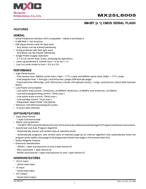
MCH0211 OhmCraft’s revolutionary fine line, thick film technology, called FineFilm, provides an entirely new level of stability and voltage ratings in chip resistors. Our MCH series of resistors meets the same high standards as our HVC series, but with the added feature of an extended temperature range.
♦Voltage Ratings to 40,000 Volts ♦Ohmic Values to 1,000 Gigohms ♦Ultra High Stability ♦Tight Tolerances ( to 0.1% ) ♦Low TCR and VCR ♦Very Low noise ♦Extended Temperature Range (-55ºC to +125ºC) ♦Custom Configurations
The usual hybrid technologies for manufacturing resistors depend upon composite materials that have limitations. Traditional thick-film methods severely limit performance characteristics and thin-film methods are limited in attainable ohmic values. The FineFilm method of manufacturing offers the best characteristics of both methods, plus adds many unique features. FineFilm resistors feature a longer, high-aspect ratio trace of lower resistivity film. The combination of long line, high-aspect ratio, and higher conductivity film, give FineFilm Note 1: Other standard & custom case sizes are available including: 0403, 0502, 0504, 1004, 1210 & 2510 Note 2: The continuous maximum voltage applied cannot exceed the maximum power rating. Maximum Continuous Voltage: FineFilm high voltage chip resistors offer voltage ratings that are much higher than conventional screen printed resistors of the same size and resistive value. MCH Series Military Grade High Voltage Chip Resistors Ratings Case Size1 0402 0503 0603 0805 1005 1206 1505 2010 2208 2512 3512 Max. Power (W) 0.040 0.050 0.060 0.200 0.250 0.330 0.330 1.000 0.750 2.000 3.000 Max. Voltage2 (V) (In air) 300 350 400 600 750 1000 1200 1700 2000 2500 3500 Max. Voltage (V) (Potted) 4000 6000 6000 10K 13K 16K 19K 30K 35K 40K 50K Resistance Range (ohms) 1K-20G 1K-200G 1K-300G 1K-350G 1K-450G 1K-500G 5K-750G 10K-1T 5K-1.5T 10K-2.0T 10K-2.0T Maximum Continuous Voltage Ratings050010001500200025003000350004020503060308051005120615052010220825123512Max. VoltageOhmCraftConventional resistors unmatched design efficiency, versatility, linearity, stability and low noise. The FineFilm method allows control of process parameters to very tight tolerances. The result is chip resistors with outstanding stability and high voltage ratings.
Using the same method, a complete line of FineFilm leaded resistors, dividers and networks are manufactured. For information on those products, please refer to the appropriate data sheets.
元器件交易网www.cecb2b.comMCH0211
L = Length W = Width T = Thickness D = Pad dimension
How to build a part number…. Type Case size TCR1 Value2 Tolerance3 Termination MCH High Voltage Chip See dimension table above E = + 25ppm/ºC H = + 50ppm/ºC K = + 100ppm/ºC L = + 200ppm/ºC Resistance value expressed as a four digit number where the first three num-bers are the signifi-cant value, and the forth number is the number of zeros. B = + 0.1 % C = + 0.25 % D = + 0.5 % F = + 1.0 % G = + 2.0% J = + 5.0 % K = + 10 % N = + 15 % L = + 20 % M = + 30 % P = + 50 % B = Solderable wrap-around
(solder coated with nickel barrier) S = Solderable single surface
(flip-chip) G = Wire Bond able (gold)
U = Bondable wraparound
(gold)
Example: For a High Voltage, 125 Meg-ohm resistor with case size of 0805,
a TCR of + 50 ppm/C, a +1% tolerance, and wrap-around solderable terminations - the part number would be: MCH0805H1256FB
RHOPOINT COMPONENTSHurst Green, Oxted, Surrey, RH8 9AXTel: +44 (0) 1883 717988 Fax: +44 (0) 1883 712938Email: sales@rhopointcomponents.comWeb: www.rhopointcomponents.com
Dimensions Wrap-around Type B & U terminations
Case Size ? Length (L) (mils) Width (W) (mils) Thickness (T) Max. (mils) Pad (D) (mils)
0402 40 + 5 20 + 3 20 10 (+ 5) 0403 40 + 5 30 + 5 20 10 (+ 5) 0502 50 (+10,-5) 25 + 5 20 10 (+ 5) 0503 55 (+10,-5) 30+ 5 20 6 (+ 2) 0504 50 (+10,-5) 40+ 5 20 6 (+ 2) 0603 63 (+10,-5) 31 + 5 20 10 (+10,-5) 0805 79 (+10,-5) 50 + 5 25 10 (+10,-5) 1004 100 (+10,-5) 40 + 5 25 15 (+10,-5) 1005 100 (+10,-5) 50 + 5 25 15 (+10,-5) 1206 126 (+10,-5) 63 + 5 30 15 (+10,-5) 1210 126 (+10,-5) 98 + 5 30 15 (+10,-5) 1505 150 (+10,-5) 50 + 5 30 15 (+10,-5) 2010 200 (+10,-5) 100 + 5 30 20 (+10,-5) 2208 225 (+10,-5) 75 + 5 30 20(+10,-5) 2510 250 (+10,-5) 100 + 5 30 20 (+10,-5) 2512 250 (+10,-5) 125 + 5 30 20 (+10,-5) 3512 350 (+10,-5) 125 + 5 30 20 (+10,-5)
Bondable Type G & S terminations
Note 1: TCR measured from –55ºC to +125ºC. Note 2: Value is dependent on case size. Note 3: Tolerance is dependent on case size & value.