131P474X2600S02中文资料
士林SS2系列变频器说明书_中文版V1.03
前言感谢您长期对本公司产品的使用与支持。
本公司研发团队与国内研究机构及世界大厂长期技术合作下,不断致力于各项产品的研发,在FA相关产品方面士林电机已达国际水准。
凭借多年推广变频器的努力与广纳客户的需求,经过严密的规划与设计,推出SS2-021/SS2-023/SS2-043系列变频调速器。
在产品的开发过程、成品的验证与产品的制造,皆经过严密且有系统的控管。
士林电机的产品品质绝对值得客户的信赖,也是您最佳的选择。
客户如有特殊用途,请与我们联络。
对于客户的委托,我们会以最坚强的专业背景与最严谨的态度,在最短时间内为客户设计专用的变频调速器,以满足客户特殊的需求。
为充分发挥产品应有的优异性能与维护人员及设备的安全,在使用前请详细阅读本使用手册,并且妥善保存,以备日后调校与保养时使用。
目录1.说明书导读 (1)2.交货检查 (2)2.1铭牌说明 (2)2.2型号说明 (2)2.3订货代号说明 (2)3.士林变频器介绍 (3)3.1电气规格 (3)3.2一般规格(变频器特性) (5)3.3外形尺寸 (7)3.4各部分名称 (9)3.5安装与配线 (11)3.6外围配备选择 (24)4.基本操作 (30)4.1变频器的操作模式 (30)4.2各模式下的基本操作程序 (34)4.3运转 (38)5.参数说明 (40)5.1转矩补偿(P.0,P.46) (40)5.2输出频率范围(P.1,P.2,P.18) (41)5.3基底频率、基底电压(P.3,P.19,P.47) (41)5.4多段速运行(P.4~P.6,P.24~P.27,P.142~P.149) (42)5.5加减速时间(P.7,P.8,P.20,P.21,P.44,P.45) (44)5.6电子热动电驿容量(P.9) (45)5.7直流制动(P.10,P.11,P.12) (45)5.8启动频率(P.13) (46)5.9适用负载选择(P.14,P.98,P.99,P.162~P.169) (47)5.10JOG运行(P.15,P.16) (49)5.11失速防止(P.22,P.23,P.66) (50)5.12输出频率滤波常数(P.28) (51)5.13加减速曲线(P.29) (51)5.14回生制动(P.30,P.70) (53)5.15载波动作选择(P.31) (53)5.16通讯功能(P.32,P.33,P.36,P.48~P.53,P.153,P.154) (54)5.17运转速度显示(P.37) (69)5.182-5端子输入信号与目标频率(P.38,P.73,P.139,P.140,P.141) (69)5.194-5端子输入信号与目标频率(P.17,P.39) (72)5.20多功能输出(P.40,P.85,P.64,P.74,P.120,P.187) (73)5.21输出频率检出范围(P.41) (76)5.22输出频率检出值(P.42,P.43) (77)5.23AM端子(P.54~P.56,P.190,P.191) (77)5.24再启动功能(P.57,P.58,P.150) (78)5.25操作键盘的旋钮设定值锁定操作选择(P.59) (79)5.26输入信号滤波常数(P.60) (80)5.27遥控功能(P.61) (80)5.28零电流检出(P.62,P.63) (82)5.29复归功能(P.65,P.67,P.68,P.69) (83)5.30制动选择(P.71) (84)5.31载波频率(P.72) (85)5.32停止功能选择(P.75) (85)5.33参数写保护(P.77) (86)5.34正反转防止选择(P.78) (86)5.35操作模式选择(P.79) (87)5.36多功能控制端子功能选择(P.80~P.84,P.86) (88)5.37滑差补偿系数(P.89) (91)5.38回避频率(P.91~P.96) (92)5.39程序运行模式(P.100~P.108,P.111~P.118,P.121~P.123,P.131~P.138) (92)5.40操作器监视选择功能(P.110) (95)5.41零速功能(P.151,P.152) (95)5.42过转矩检出(P.155,P.156) (96)5.43外部端子滤波功能(P.157) (96)5.44外部端子上电使能功能(P.158) (96)5.45节能控制(P.159) (97)5.46多功能显示(P.161) (97)5.47PID功能(P.170~P.183,P.223~P.225) (98)5.484-5端子断线处理功能(P.184) (101)5.49比例联动功能(P.185) (101)5.50变频器程序版本号(P.188) (102)5.51出厂设定功能(P.189) (102)5.522-5端子输入信号(P.192~P.195) (103)5.534-5端子输入信号(P.196~P.199) (104)5.54齿隙补偿功能(P.229~P.233) (105)5.55摆频功能(P.234~P.239) (106)5.56辅助频率功能(P.240) (107)5.57启动前有直流制动功能(P.242~P.244) (107)5.58冷却风扇停车方式功能选择(P.245) (108)5.59工频-变频运行功能(P.247~P.250) (108)5.60SCP短路保护功能(P.287) (110)5.61异警记录参数(P.288~P.291) (111)5.62累积运行时间功能(P.292,P.293) (111)5.63密码保护功能(P.294,P.295) (112)5.64马达控制模式(P.300,P.301) (112)5.65马达参数(P.302~P.309) (114)5.66滑差补偿增益(P.320) (115)5.67转矩补偿滤波(P.321) (115)5.68参数拷贝功能(P.994,P.995)(需购买DU06操作器) (115)5.69异警记录清除(P.996) (116)5.70变频器重置(P.997) (116)5.71参数还原为默认值(P.998,P.999) (116)6.维护与检查 (117)6.1日常检查项目 (117)6.2定期检查(停机检查)项目 (117)6.3部分零件的定期更换 (117)6.4测量变频器的绝缘电阻 (118)6.5测量电机的绝缘电阻 (118)6.6IGBT模块测验 (118)附录一参数表 (119)附录二异警代码表 (127)附录三警告代码表 (129)附录四异警现象与对策 (130)附录五可选配件 (131)附录六欧洲规范兼容性说明 (133)修订记录 (135)说明书导读1.说明书导读士林电机SS2系列变频器,为符合市面上大部分的应用层面需求,设计了许多复杂的参数功能,对于初次接触变频器的客户,可能会造成使用上的困扰,因此我们希望读者能够仔细阅读说明书的每一部分,以便充分掌握此变频器的使用方法。
微星P43-C51说明书,简体中文
1
2
DIMM1 DIMM2 DIMM3 DIMM4
DIMM1 DIMM2 DIMM3 DIMM4
已安装 未安装
注意
• 由于DDR3内存不与DDR2内存互换,并且DDR3不向下兼容,所以你应该把DDR3内 存插入DDR3插槽中。
• 在双通道模式下,一定要使用同类型同密度的内存模块,插入不同颜色的内存插槽 中。
注意
过热 温度过高会严重损害CPU和系统,请务必确认所使用的降温风扇始终能够正常工作,保 护CPU以免过热烧毁。确认,您已在CPU和散热片之间涂抹了一层平滑的散热硅胶(或 热胶带) 以增强散热。 更换 CPU 更换CPU时,请先关闭ATX电源供应或从地面拔掉电源插头以确保CPU的安全。 超频 主板设计支持超频。然而,请确认您的配置能够接受这样非常规的设定。在超频时,不 推荐任何超技术规范之外的动作。我们不担保损坏或因为在产品规格之外不规范的操作 导致的风险。
ATX 4-pin 电源接口: JPWR2
此接口用于为CPU提供电源。
2.G1.rGouronudnd
4.+31.+21V2V
注意
• 确认所有接口都已正确的连接到ATX电源适配器上,以确保主板提供稳定的工作电 流。
• 为了系统稳定,强烈建议您使用350瓦(或更大功率)的电源适配器。
Sc-11
▍ MS-7519 主板 后置面板
▶ USB 端口 USB (通用串行总线)端口用于连接USB设备,如键盘,鼠标或其他USB兼容设备。
▶ 1394 端口 (选配) 后置面板 IEEE1394 端口用于连接 IEEE1394 设备。
▶ LAN
标准的RJ-45插孔以连接到局域网(LAN),
黄色
B1213RU中文资料

232 Tosca Drive Stoughton, MA 02072 USA T: (781) 344-8226 F: (781) 344-8481 E: sales@ W:
Physical
Case Size Case Material Weight 2.0 x 1.0 x 0.40 Inches (50.8 x 25.4 x 10.2 mm) Metal with Non-Conductive Base (UL94-V0) 1.13 Oz (32g) Conditions MIL HDBK 217F, 25°C, Gnd Benign Min. Typ. Max. Units 700 kHours UL 1950, EN 60950, IEC 60950 UL, cUL; File No. E245422 Min. -0.7 -0.7 Typ. Max. 42.0 84.0 260.0 5,000 Units VDC °C mW
Parameter Input Start Voltage Input Filter Reverse Polarity Input Current Short Circuit Input Power
Conditions Min. Typ. Max. 24 VDC Input 8.0 8.5 9.0 48 VDC Input 14.0 16.0 18.0 (Pi) Filter (Complies with EN55022 Class “A”) 1.0 3,500 Conditions Dual Output , Balanced Loads Vin = Min to Max Iout = 10% to 100% Over Line, Load & Temp. 120 25% Load Step Change Continuous Conditions 60 Seconds Flash Tested For 1 Sec 500 VDC 100 kHz, 1V Min. 1,500 1,650 1,000 350 Conditions Typ. Max. 150 ±1.5 ±0.01 250 ±2.5 ±0.02 Min. Typ. ±0.5 ±0.5 ±0.1 75 100 15
联想 ThinkPad 13 2nd Gen 和S2 2nd Gen 用户指南
预防问题的常用技巧 . . . . . . . . . . . 61 故障诊断 . . . . . . . . . . . . . . . . 61
计算机停止响应 . . . . . . . . . . . . 61 处理键盘上泼溅的液体 . . . . . . . . . 62 错误消息 . . . . . . . . . . . . . . . 62 蜂鸣声错误 . . . . . . . . . . . . . . 64 内存条问题 . . . . . . . . . . . . . . 65 以太网问题 . . . . . . . . . . . . . . 65 无线局域网问题 . . . . . . . . . . . . 66 蓝牙问题 . . . . . . . . . . . . . . . 67 ThinkPad 指针设备问题 . . . . . . . . . 67 键盘问题 . . . . . . . . . . . . . . . 67 计算机屏幕问题 . . . . . . . . . . . . 68 外接显示器问题 . . . . . . . . . . . . 70 音频问题 . . . . . . . . . . . . . . . 71 指纹读取器问题 . . . . . . . . . . . . 72 电池问题 . . . . . . . . . . . . . . . 72 交流电源适配器问题 . . . . . . . . . . 73 电源问题 . . . . . . . . . . . . . . . 73 电源按钮问题 . . . . . . . . . . . . . 74 引导问题 . . . . . . . . . . . . . . . 74 睡眠与休眠问题 . . . . . . . . . . . . 74 固态驱动器问题 . . . . . . . . . . . . 75 软件问题 . . . . . . . . . . . . . . . 75 USB 问题 . . . . . . . . . . . . . . . 75
启英泰伦 CI1312 数据手册说明书
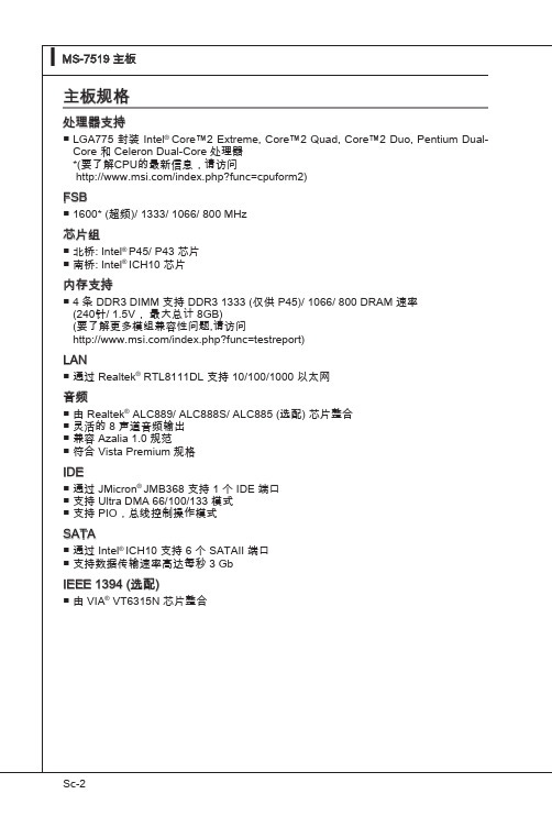
CI1312数据手册高性能神经网络智能语音芯片SOP16长9.9mm宽6.0mm高1.7mm•脑神经网络处理器(BNPU)–BNPU V3,支持DNN\TDNN\RNN\CNN等神经网络及并行矢量运算,可实现语音识别、声纹识别、命令词自学习、语音检测及深度学习降噪等功能•CPU和存储器–CPU主频可达220MHz–内置2MBytes Flash存储器–内置640KBytes SRAM–内置512bit eFuse,可用于应用加密•Audio Codec–高性能低功耗audio ADC,SNR≥95dB–低功耗audio DAC,SNR≥95dB •PWM–支持3路PWM接口•GPIO–5个高速GPIO,响应速率可达20MHz–全部GPIO支持5V输入•复位和电源管理–内置电源管理单元PMU–PMU输入电压范围: 3.6V到5.5V–内置上电复位(POR)–内置电压检测(PVD)•时钟–内置RC振荡器•通讯接口–1路IIC接口–2路UART接口,支持5V通讯,支持最高3Mbps速率•定时器和看门狗–内置4组32位定时器和2组看门狗目录1概述 (3)1.1功能描述 (3)1.2芯片规格 (4)2引脚图和功能描述 (6)2.1引脚图 (6)2.2管脚描述 (7)2.3复用功能 (9)3电气特性 (10)4封装信息 (12)5订购信息 (13)6应用方案 (14)6.1应用参考电路图 (14)6.2应用其它注意事项 (15)1概述1.1功能描述CI1312是启英泰伦研发的新一代高性能神经网络智能语音芯片,集成了启英泰伦自研的脑神经网络处理器BNPU V3和CPU内核,系统主频可达220MHz,内置高达640KByte的SRAM,集成PMU电源管理单元和RC振荡器,集成单通道高性能低功耗Audio Codec和多路UART、IIC、PWM、GPIO等外围控制接口。
芯片仅需少量电阻电容等外围器件就可以实现各类智能语音产品硬件方案,性价比极高。
ISP2312中文资料

S i m p l i f y QThe ISP2312 is a highly integrated single-chip, dual-channel, bus master, Fibre Channel processor that targets storage, clustering, and networking applications. This chip connects a conventional PCI bus or PCI-X bus to a 2-Gb Fibre Channel loop or to a point-to-point Fibre Channel port.The ISP2312 is a fully autonomous device, capable of managing multiple I/O operations and associated data transfers from start to finish without host intervention.The ISP2312 balances the advanced bus speeds and efficiency of PCI-X with exceptional 2-Gb Fibre Channel performance. Fibre Channel support for SCSI, IP, and VI allows the ISP2312 to target a wide spectrum of storage and system area networks (SANs).Features■66/133-MHz, 64-bit, true multifunction PCI-X host bus interface■Backward compatible to standard 33/66-MHz PCI■5-V tolerant PCI interface■Compliance with PCI Local Bus Specification revision 2.2 and PCI-X Specification revision1.0a■Supports Fibre Channel-arbitrated loop (FC-AL), FC-AL-2, point-to-point, and switchedfabric topologies■Supports full-duplex communications in all Fibre Channel topologies■Supports Fibre Channel protocol-SCSI(FCP-SCSI), Fibre Channel Internet protocol(IP), and Fibre Channel-virtual interface(FC-VI) protocol■Compliance with PCI Bus Power Management Interface Specification Revision 1.1(PC99)■Compliance with ANSI SCSI standards for class1, class2, class 3, and intermix FibreChannel service:❒Second Generation FC Generic Services Definition (FC-GS-2), NCITS 288.200x,Project 1134-D, revision5.3❒Third Generation FC Generic Services Definition (FC-GS-3) draft, revision 6.2❒Fibre Channel-Physical and Signaling Interface (FC-PH), X2.230:1994❒SCSI-3 Fibre Channel Protocol(SCSI-FCP), X3.269:1996❒Fibre Channel-Arbitrated Loop-2(FC-AL-2), Project 1133-D, revision 6.5❒Fibre Channel-Private Loop Direct Attach Technical Report (FC-PLDA),NCITS/TR-19:1998❒SCSI-3 Architecture Model (SAM),X3T10/994D/Rev 18❒SCSI-3 Controller Command Set,X3T10/Project 1047D/Rev 6c■Two concurrently operating 2Gbps capable Fibre Channel nodes■Supports up to 400 MBps sustained Fibre Channel data transfer rate■Supports SCSI initiator, initiator/target, and target modes■Onboard, enhanced RISC processor■Onboard 2-Gb serial transceivers■Automatically negotiates the Fibre Channel bit rate(1 or 2 Gb)■Supports PCI dual-address cycle and cache commandsISP2312 Data SheetDual 2-Gb Fibre Channel to 133-MHz PCI-X ControllerM■No host intervention required to execute complete SCSI, IP, or VI operations■Supports multi-ID aliasing in target mode■Supports JTAG boundary scan, full scan, and memory built-in self-test (BIST)■Supports up to 128 KB flash per channel■Supports up to 4 MB SRAM per channel Subsystem OrganizationTo maximize I/O throughput and improve host and Fibre Channel utilization, the ISP2312 incorporates two high-speed, proprietary RISC processors; two Fibre Channel protocol modules (FPMs); integrated frame buffer memory; and a PCI bus, 10-channel, bus master DMA controller. The FPMs and PCI bus DMA controller operate independently and concurrently under the control of the onboard RISC processors for maximum system performance.The complete I/O subsystem solution using the ISP2312 and directly connected hard drives is shown in figure1.Figure 1. I/O Subsystem Design Using the ISP2312PCI-X InterfaceThe ISP2312 PCI-X interface has the following features:■66- or 133-MHz, 64-bit, true multifunction, intelligent bus master PCI-X interface ■33-MHz and 66-MHz 64-bit intelligent bus master conventional PCI interface (PCI 2.2)■64-bit host memory addressing (dual-address cycle)■10-channel DMA controller■32-bit PCI target mode for communication with the host ■Pipelined DMA registers for efficient scatter/gather operations■32-bit DMA transfer counter to support large I/O transfer lengths■Support for PCI-X split transactions■Support for PCI power management■Support for the message signaled interrupt function■Support for flash BIOS PROM■Support for subsystem ID■ 3.3-V and 5.0-V tolerant PCI-X I/O buffersMThe ISP2312 is designed to interface directly to the PCI or PCI-X bus and operate as a 64-bit DMA bus master. This function is accomplished through a PCI bus interface unit (PBIU) containing an onboard DMA controller. The PBIU generates and samples PCI control signals, generates host memory addresses, and facilitates the transfer of data between host memory and the onboard frame buffer. It also allows the host to access the ISP2312 internal registers and communicate with the onboard RISC processors.The ISP2312 onboard DMA controller consists of 10independent DMA channels that initiate transactions on the PCI bus and transfer data between the host memory and frame buffer or the RISC RAM.The PBIU internally arbitrates between the DMA channels and alternately services them. Each DMA channel has a set of DMA registers that are programmed for transfers by the RISC processors. Fibre Channel InterfaceThe ISP2312 provides two onboard 2-Gb transceivers for direct connection to the Fibre Channel ports on copper media.Fibre Channel Protocol ModulesThe ISP2312 FPMs have the following features:■Support for one Fibre Channel port■Support for 1- and 2-Gb serial interfaces■Auto-negotiation to support 1-Gb or 2-Gb devices■Full-duplex data transfer rate up to 400 MBps ■Integrated frame buffer that supports up to a 2112-byte frame payload■8B/10B encoder and decoder with clock skew managementEach FPM transmits and receives data at the full Fibre Channel rate of 106.25 or 212.50 MBps. The on-chip frame buffer includes separate areas for received data and transmit data, as well as areas for managing special frames such as command and response. Each FPM receive path validates and routes frames received from the Fibre Channel to the appropriate area in the frame buffer. The transmit path transmits frames from the frame buffer to the Fibre Channel. Each FPM automatically handles frame delimiters and frame control.RISC ProcessorsThe ISP2312 RISC processors have the following features:■Execution of multiple I/O control blocks from the host memory■Reduced host intervention and interrupt overhead■One interrupt or less per I/O operationOne of the major features of the ISP2312 is its ability to handle complete I/O transactions from start to finish with no host intervention. This high level of integration is accomplished with the onboard RISC processors. The ISP2312 RISC processors control the chip interfaces; execute simultaneous, multiple IOCBs; and maintain the required thread information for each transfer.Multiprotocol SupportThe ISP2312 firmware implements a multitasking host adapter that provides the host system with IP communications, complete SCSI command and data transport capabilities, and VI communications, thus freeing the host system from simultaneous execution of SCSI, IP, and VI traffic. The firmware provides two interfaces to the host system: the command interface and the Fibre Channel transport interface. The single-threaded command interface facilitates debugging, configuration, and error recovery. The multithreaded transport interface maximizes use of the Fibre Channel and host buses.The ISP2312 can operate simultaneously in SCSI initiator and target modes, and supports SCSI, IP, and VI protocols concurrently.Software DriversThe ISP2312 supports a host software interface similar to the QLogic parallel SCSI and single channel Fibre Channel processor families. Existing ISP2300 software drivers for all major operating systems are easily modified to support the ISP2312. The ISP2312 also supports FCP-SCSI, IP, and VI software drivers for most major operating systems.PackagingThe ISP2312 is available in a 388-pin thermally enhanced plastic ball grid array (EPBGA-T) package. The ISP2312 power supply voltages are 2.5 and 3.3, with PCI-X I/O voltages up to 5.M© 2002–2003 QLogic Corporation. All rights reserved worldwide.QLogic is a trademark of QLogic Corporation.All other brand and product names are trademarks or registered trademarks of their respective owners.QLogic Corporation, 26650 Aliso Viejo Parkway, Aliso Viejo, CA 92656, (800) 662-4471 or (949) 389-6000Specifications are subject to change without notice.February 21, 2003。
2SA1312资料

TOSHIBA Transistor Silicon PNP Epitaxial Type (PCT process)2SA1312Audio Frequency Low Noise Amplifier Applications• High voltage: V CEO = −120 V• Excellent h FE linearity: h FE (I C = −0.1 mA)/ h FE (I C = −2 mA)h= 0.95 (typ.)• High h FE: h FE = 200~700• Low noise: NF (2) = 0.2dB (typ.), 3dB (max) at f = 1 kHz • Complementary to 2SC3324 • Small packageAbsolute Maximum Ratings (Ta = 25°C)Characteristics Symbol RatingUnitCollector-base voltage V CBO −120 V Collector-emitter voltage V CEO −120 V Emitter-base voltage V EBO −5 V Collector current I C −100 mABase currentI B−20 mA Collector power dissipation P C 150 mW Junction temperature T j 125 °C Storage temperature rangeT stg−55~125 °CNote: Using continuously under heavy loads (e.g. the application of hightemperature/current/voltage and the significant change in temperature, etc.) may cause this product to decrease in the reliability significantly even if the operating conditions (i.e. operating temperature/current/voltage, etc.) are within the absolute maximum ratings.Please design the appropriate reliability upon reviewing the Toshiba Semiconductor Reliability Handbook (“Handling Precautions”/“Derating Concept and Methods”) and individual reliability data (i.e. reliability test report and estimated failure rate, etc).MarkingUnit: mmJEDEC TO-236MODJEITA SC-59 TOSHIBA 2-3F1AWeight: 0.012 g (typ.)Electrical Characteristics (Ta = 25°C)Characteristics Symbol TestCondition MinTyp.Max Unit Collector cut-off current I CBO V CB=−120 V, I E= 0 ⎯ ⎯−0.1μA Emitter cut-off current I EBO V EB=−5 V, I C= 0 ⎯⎯−0.1μADC current gain h FE(Note)V CE=−6 V, I C=−2 mA 200 ⎯ 700Collector-emitter saturation voltage V CE (sat)I C=−10 mA, I B=−1 mA ⎯⎯−0.3V Transition frequency f T V CE=−6 V, I C=−1 mA ⎯ 100 ⎯ MHz Collector output capacitance C ob V CB=−10 V, I E= 0, f = 1 MHz ⎯ 4 ⎯ pFNF (1) V CE=−6 V, I C=−0.1 mA, f = 100 Hz,Rg = 10 kΩ⎯ 0.5 6Noise figureNF (2) V CE=−6 V, I C=−0.1 mA, f = 1 kHz,Rg = 10 kΩ⎯ 0.2 3dBNote: h FE classification GR (G): 200~400, BL (L): 350~700 ( ) marking symbolRESTRICTIONS ON PRODUCT USE20070701-EN GENERAL •The information contained herein is subject to change without notice.•TOSHIBA is continually working to improve the quality and reliability of its products. Nevertheless, semiconductor devices in general can malfunction or fail due to their inherent electrical sensitivity and vulnerability to physical stress. It is the responsibility of the buyer, when utilizing TOSHIBA products, to comply with the standards of safety in making a safe design for the entire system, and to avoid situations in which a malfunction or failure of such TOSHIBA products could cause loss of human life, bodily injury or damage to property.In developing your designs, please ensure that TOSHIBA products are used within specified operating ranges as set forth in the most recent TOSHIBA products specifications. Also, please keep in mind the precautions and conditions set forth in the “Handling Guide for Semiconductor Devices,” or “TOSHIBA Semiconductor Reliability Handbook” etc.• The TOSHIBA products listed in this document are intended for usage in general electronics applications (computer, personal equipment, office equipment, measuring equipment, industrial robotics, domestic appliances, etc.).These TOSHIBA products are neither intended nor warranted for usage in equipment that requires extraordinarily high quality and/or reliability or a malfunction or failure of which may cause loss of human life or bodily injury (“Unintended Usage”). Unintended Usage include atomic energy control instruments, airplane or spaceship instruments, transportation instruments, traffic signal instruments, combustion control instruments, medical instruments, all types of safety devices, etc.. Unintended Usage of TOSHIBA products listed in his document shall be made at the customer’s own risk.•The products described in this document shall not be used or embedded to any downstream products of which manufacture, use and/or sale are prohibited under any applicable laws and regulations.• The information contained herein is presented only as a guide for the applications of our products. No responsibility is assumed by TOSHIBA for any infringements of patents or other rights of the third parties which may result from its use. No license is granted by implication or otherwise under any patents or other rights of TOSHIBA or the third parties.• Please contact your sales representative for product-by-product details in this document regarding RoHS compatibility. Please use these products in this document in compliance with all applicable laws and regulations that regulate the inclusion or use of controlled substances. Toshiba assumes no liability for damage or losses occurring as a result of noncompliance with applicable laws and regulations.。
2SK1317中文资料(renesas)中文数据手册「EasyDatasheet - 矽搜」

5.瑞萨科技半导体产品不是设计或在设备制造中使用 或根据情况使用系统中,人生命是潜在威胁.请联系 瑞萨科技公司或考虑使用此报告任何特定目,如设备或系统,运输,车辆,医疗,航空航天,核 能,或海底中继器使用一个产品时,经授权瑞萨科技产品经销商.
3.包含在这些资料,包括产品数据,图,表,程序和所有信息 算法表示在公布这些材料时间对产品信息,并有可能由株式会社瑞萨科技,恕不另行通知变动,由 于产品改进或其他原因.因此,建议客户购买此处所列产品之前,请联系瑞萨科技公司或瑞萨 科技公司授权产品分销商最新产品信息.
这里描述信息可能包含技术错误或印刷错误. 瑞萨科技公司不承担任何损害,责任或其他损失,这些不准确或错误上升不承担任何责任.
°C )
在这一领域
由R限于
DS (on)
Ta = 25°C
0.01 10 30 100 300 1,000 3,000 10,000
漏极至源极电压V
DS (V)
典型传输特性
2.0
1.6 (A)
D
1.2
VDS = 20 V
脉冲测试
0.8 漏电流I
0.4
75°C TC = 25°C
–25°C
0
2
4
门源电压V
6 8 10 GS (V)
3
额定值
单元
1500
V
±20
V
2.5
A
7
A
2.5
A
- 1、下载文档前请自行甄别文档内容的完整性,平台不提供额外的编辑、内容补充、找答案等附加服务。
- 2、"仅部分预览"的文档,不可在线预览部分如存在完整性等问题,可反馈申请退款(可完整预览的文档不适用该条件!)。
- 3、如文档侵犯您的权益,请联系客服反馈,我们会尽快为您处理(人工客服工作时间:9:00-18:30)。
Document Number: 42033Revision 17-Nov-03www.vishay.com
98
Type 131PVishay Sprague
For technical questions, contact spresale@vishay.comFEATURES• Suggested replacement for Type 196P• Moderate cost• Small size• High peak current ratings• High corona starting voltage
DC Life Test: 140% of rated voltage for 250 hours @ + 125°C.No open or short circuits. No visible damage. MaximumCapacitance Change: ± 5%. Minimum IR = 60% of initial limit.Maximum DF = 1.0%.Moisture Resistance: MIL-STD-202, Method 106E, 10 cycles. No visible damage. Maximum Capacitance Change: ± 3%. Minimum IR = 60% of initial limit. Maximum DF = 1.2%.Thermal Shock and Immersion Cycling: No visible damage. Maximum Capacitance Change: ± 1%. Minimum IR = 50% ofinitial limit. Maximum DF = 1.2%.
0.0100.0220.0470.100.220.47 131P103X9600S02* 131P223X9600S02* 131P473X9600S02*131P104X9600S02131P224X9600S02131P474X9600S020.312 x 0.875 [7.92 x 22.23]0.400 x 0.875 [10.16 x 22.23]0.400 x 1.375 [10.16 x 34.93]0.562 x 1.375 [14.27 x 34.93]0.670 x 1.625 [17.02 x 41.28]0.750 x 2.375 [19.05 x 60.33]0.0370.0580.0850.1490.3540.6561.53.37.015.033.070.00.0250.0410.0590.1040.2470.4591.02.34.910.523.149.0
ORDERING INFORMATION* All standard inventoried Part Numbers will be stocked in terminal and case style number S04.1000 WVDC / 500 VAC0.0100.0220.0470.100.220.47 131P103X91K0S02* 131P223X91K0S02* 131P473X91K0S02* 131P104X91K0S02* 131P224X91K0S02* 131P474X91K0S02*0.400 x 0.875 [10.16 x 22.23]0.400 x 1.375 [10.16 x 34.93]0.562 x 1.375 [14.27 x 34.93]0.670 x 1.625 [17.02 x 41.28]0.750 x 2.125 [19.05 x 53.98]1.000 x 2.375 [25.40 x 60.33]0.0390.0790.1330.2410.4270.7722.55.511.025.055.0117.00.0270.0550.0930.1680.2980.5401.73.87.717.538.581.9
PERFORMANCE CHARACTERISTICSOperating Temperature: - 65°C to + 125°C.Capacitance Range: 0.01µF to 0.47µF.Capacitance Tolerance: ±20%, ± 10%, ±5%, ±2%.Voltage Rating: 600 WVDC to 1000 WVDC.Dissipation Factor: 1.0% maximum.Voltage Test: 200% of rated DC voltage for 2 minutes.Insulation Resistance: At + 25°C: 20,000 Megohm - Microfarads or 30,000 Megohm minimum. At + 125°C:20 Megohm - Microfarads or 250 Megohm minimum.
Capacitance Change with Temperature: At - 65°C,- 10% typical. At + 125°C, + 10% typical.
STANDARD RATINGS in inches [millimeters]PART NUMBER±10%
TOLERANCECAPACITANCE(µF)NOMINAL CASE SIZE
D x L
Max. rmsCURRENT @ +85°CMax.PEAKCURRENT@ + 85°CMax. rmsCURRENT @ +125°CMax.PEAKCURRENT@ + 125°C
PHYSICAL CHARACTERISTICSLead Pull: 5 pounds (2.3 kilograms) for one minute. No physical damage.Lead Bend: After three complete consecutive bends, no damage.Lead Wire: Bare, solid tinned wire. Case Diameters: .312" [7.92mm], No. 22 AWG; .400" [10.16mm] and over, No. 20 AWG.Marking: Sprague® trademark, type or part number,
capacitance and voltage.
131PTYPEThis is expressed in picofarads.The first two digits are thesignificant figures. The third is thenumber of zeros to follow. Valuesmust conform to the decade ratingfor the tolerance specified.103CAPACITANCEX9CAPACITANCETOLERANCEX0 = ± 20%X9 = ± 10%(Inventoried)X5 = ± 5%X2 = ± 2%600DC VOLTAGERATINGThis is expressed involts. (1000 WVDCcoded as 1K0)S = Wire leadsT = Soldering tab*STERMINAL
Note: Inventorieditems are all S04.
04CASESTYLE
*Soldering tabs are available only on case diameters equal to or greaterthan 0.400" [10.16mm]. Consult the factory for special case styles andterminal configurations.
ENVIRONMENTAL CHARACTERISTICSVibration Test (Condition B): No mechanicaldamage, short, open or intermittent circuits.
Film Snubber CapacitorsMetal-Case, Paper/Polyester, DielectricExtended Foil Electrodes
600 WVDC / 370 VAC
元器件交易网www.cecb2b.comLegal Disclaimer NoticeVishay
Document Number: 91000www.vishay.comRevision: 08-Apr-051
NoticeSpecifications of the products displayed herein are subject to change without notice. Vishay Intertechnology, Inc.,or anyone on its behalf, assumes no responsibility or liability for any errors or inaccuracies.
Information contained herein is intended to provide a product description only. No license, express or implied, byestoppel or otherwise, to any intellectual property rights is granted by this document. Except as provided in Vishay'sterms and conditions of sale for such products, Vishay assumes no liability whatsoever, and disclaims any expressor implied warranty, relating to sale and/or use of Vishay products including liability or warranties relating to fitnessfor a particular purpose, merchantability, or infringement of any patent, copyright, or other intellectual property right.