南衡8142-07A说明书
8142pro+7++技术手册(英)
1. IntroductionThis manual describes the 8142Pro+ single display scale terminal (PRGN-XXX7 ) , which is tailored design to meet the vehicle and floor scale needs .Installation and service procedure should be performed only by authorized personnel .1.1 8142Pro+ 7 Features•Single 7 digits numeric vacuum fluorescent displays•21 position keypad•Input for up to eight 350Ω analog load cells•The selectable increments from 1000 to 50,000•A/D internal Resolution: 1,000,000•Display update rate: 10 updates each second•Pushbutton and keyboard tare•Tare interlock function•The expanded weight display•Tare and clear tare automatically•Automatic zero maintenance•Motion detection and indication•Center of zero indication•Real time clock by battery back-up•100 truck ID/Tare record (8 digits truck ID)•500 transactions record ( the information include CN, time and date, truck ID, gross, tare and net ) •Subtotal by truck ID•Daily report printout•One serial communication interface (continuous mode output )•One parallel Centronics interface•High accurate delta-sigma A/D converter•TraxDSP TM vibration rejection•SMT technology1.2 8142Pro+ Specifications1.2.1 Analog Load Cell•Excitation Voltage: +10VDC, power up to eight 350Ω analog load cells•Span range: 3 ~ 32mV•Zero range: 0 ~ 25mV1.2.2 Power Requirements8142Pro+ is available in four versions, 100V, 120V , 220V and 240V . Voltage variation is from –15% to +10%, frequency is from 49Hz to 63Hz . Power consumption is 12 Watts maximum . Power is applied through a modular power plug line cord.8142Pro+ requires a true earth ground for reliable operation.The power line for 8142Pro+ must not be shared with equipment such as motors, relays, or heaters that generate line noise.1.2.3 Display and KeyboardThe enclosure of 8142Pro+ is cast zinc-aluminum alloy. The display is a 7 digits numeric vacuum fluorescent display.The keyboard consists of a flat membrane switch covered with a domed polyster overlay.1.2.4 Temperature and Humidity8142Pro+ operates over a temperature range from -10 to 40 °C at 10% to 95% humidity, noncondensing. Storage temperature range is from -40 to 60 °C at 10% to 95% humidity, noncondensing.1.2.5 Physical Dimension324204168METTLER TOLEDO8142PRO10001.3 Ordering Information8142Pro+ MODEL CONFIGURATIONex: PRGN-1037-023PRGN X X X X XXX MODEL PCB type Reserved Market DISPLAY Country PR - 8142Pro+ G-General housing N - Numeric1 –Analog L/C2 - HAP 0 3- Export 7 - Single 8 – Dual 023 - CHINA2. InstallationThis chapter gives detailed instructions and important information you will need to install 8142Pro+ scale instrument successfully. Please read this chapter thoroughly before you begin installation.2.1 Unpacking and InspectionPlease inspect the package as it is delivered by the carrier. If the shipping container is damaged, check for internal damage and file a freight claim with the carrier if necessary.If the container is undamaged, unpack the 8142Pro+ scale instrument from its protective package, noting how it was packed, and inspect each component for damage.2.2 Electrical ConnectionsPrinter2.2.1 Connect the Load Cell8142Pro+ powers up to eight 350Ω analog load cells.The wiring between 8142Pro+ and junction box is standard 6-wire cableThe analog load cell connector to the terminal is a 9 pin D-SUB female connector. The following diagram shows the pins assignments for 9 pin D-SUB connector. (Pin 9 is used to connect to the outer shield layer of cable)SIGNAL +EXC +SEN SHLD-SEN-EXC +SIG -SIG GNDPIN 1 2 3 4 5 7 8 92.2.2 Serial Port COM1 ConnectionThe serial port COM1 consist of RS-232 and 20 mA current loop.The maximum recommended cable length for RS-232 interface is 50 feet.The maximum recommended cable length for 20 mA interface is 1000 feet.The serial port COM1 connector is a 25 pin D-SUB female connector. The following diagram shows the pins assignments for COM1 connector.SIGNAL PINSHIELD GROUND 1TXD (RS-232) 2RXD (RS-232) 3SIGNAL GROUND 7, 19, 22, 23CLRX+ 8, 16CLTX+ 918CLRX- 10,Note: The transmitter of 20 mA current loop is active, the receiver is passive.Below is the pin assignment of 8142Pro+ 7 to the scoreboard .COM1 at 8142Pro+ 7 Mettler-Toledo Scoreboard9 1 CLRX+7 2 CLRX-If you want to connect your 8142Pro+ 7 to the computer , please refer to the below sheet for pin assignment .COM1 Computer ( 9 pin ) Computer ( 25 pin )2 2 33 3 27 5 72.2.3 The Parallel InterfaceThe parallel interface is standard Centronics printer interface. It is used to connect to a printer.The parallel port connector is a 25 pin D-SUB female connector. The following diagram shows the pins assignments for connector.SIGNAL PIN SIGNAL PINSTRORE 1 BUSY 11DATA BIT0 2 PAPER EMPTY 12DATA BIT1 3 SELECT 13DATA BIT2 4 AUTO FEED 14DATA BIT3 5 ERROR- 15DATA BIT4 6 INIT- 16DATA BIT5 7 SELECT- 17DATA BIT6 8 SIGNAL GND 18 ~ 25DATA BIT7 9ACK- 102.3 8142Pro+ Jumper and Switch SettingsJumper and switches on the main PCB should be set as follows:•K1-1 is the setup enable switch. This switch should be ON to access all setup parametersand be OFF in operation mode .•K1-2 is selection switch for comma. This switch should be ON to display comma (not decimal point). •K1-3 is used to access factory test mode. This switch is always OFF in the normal operation mode.•K1-4 is used to access factory test mode. This switch is always OFF in the normal operation.•W1 jumper should be removed for 3 mV/V, installed for 2 mV/V analog load cell.2.4 Minimum Increment Size for Analog Scale InputThe minimum increment size selection for an analog scale input is determined by calculating the microvolts per increment for the desired build.2.4.1 Solve the following equation for µV per increment.Increment Size x cell output x excitation voltage (15) x 1000µV per Increment = --------------------------------------------------------------------------------- Load Cell Capacity x Number of Cells or Level RatioThe increment size, scale capacity, and load cell capacity must all be measured in the same weight units, lb or kg.Load cell output is rated in mV/V (millivolts per volt of excitation), marked on load cell data tag. Mettler Toledo load cells are typically 2 mV/V. Other load cells can range from 1 mV/V to 4.5 mV/V.The load cell capacity is the rated capacity marked on load cell data tag. The number of the cells is the total number of load cells in the system , for the electronic-mechanical scale , the level ratio is the total level ratio in the system .2.4.2 Calculate the total number of increments by dividing the calibrated capacity by the increment size.Calibrated Capacity# Increments = ----------------------------Increment Size2.4.3 Microvolt build tableUse the following microvolt build table to determine if the µV per increment calculated in step 1 is within the range allowed for the total number of increments calculated in step 2. These parameters have demonstrated stable builds but smaller minimum µV per increment and larger total number of increments are possible.Microvolt Build TableTotal Number of Increment MinimumµV perIncrement Maximum mV per Increment2 mV/V3 mV/V1,000 3.0 26.0 38.02,000 1.5 13.0 19.02,500 1.2 10.4 15.23,000 1.0 8.7 12.74,000 0.75 6.5 9.55,000 0.6 5.2 7.66,000 0.5 4.4 6.48,000 0.375 3.3 4.810,000 0.3 2.6 3.820,000 0.15 1.3 1.950,000 0.1 0.52 0.76Note: 8142Pro+ should never be programmed for least than 0.5 µV per increment when used with single load cell applications and never less than 0.1 µV per increment when used with multiple load cell applications. 8142Pro+ cannot be calibrated for builds that exceed the maximum µV per increment listed in the microvolt build rate.3. 8142Pro+ OperationsThis chapter provides information that an operator will need to become familiar with the terminal and to perform its functions.3.1 8142Pro+ Display and Keyboard8142Pro+ single display version has one displays where scale data and operational message are presented. This area can display up to seven numbers each with a decimal point, comma, and annunciators. The annuniciators are:•The center-of-zero annunciator indicates that the scale is within ± ¼ increment of gross zero.•Scale in-motion ( ~ )The scale instability annunciator indicates that the scale is in motion. The annuniciator will turn off when the scale is stable. The motion sensitivity of motion detection is adjustable in setup.•Weighing mode ( Gross or NET)The 8142Pro+ will be in Net mode when a tare is active. Tare can be entered as a Preset tare value or tare may be automatically acquired when the operator presses the TARE key.•Truck IDThe truck ID annunciator indicates that you are entering a truck identification.•TIME/DATEThe time annunciator indicates TIME has been displayed. The date annunciator indicates DATE has been displayed.8142Pro+ 7 is equipped with a 21-key keypad as shown in the picture :The keypad consists of numeric keys 0 through 9 and eleven function keys.The keys perform the following functions:•NUMERIC keys are used to input numbers.•ZERO zeros the scale. The ZERO key also functions as backspace when entering data from the keypad.•TARE performs a pushbutton tare or keyboard tare if enabled in setup.•CLEAR clears a tare value and returns the scale to gross mode. The CLEAR key also functions as delete when entering data from the keypad.•Truck ID acknowledges a prompt and accepts data as truck ID entered from the keypad.•CN key is used to recall consecutive number.•RECALL is used to recall consecutive number or accumulations.•TIME/DATE key is used to enter or recall the clock and the date.•REPORT can generate and print truck-related reports.•RECORD key is used to store a weighing transaction.•ENTER/PRINT acknowledges a prompt and accepts data entered from the keypad. It also initiates a demand print output.3.2 The Basic Operator Functions3.2.1 Power-up Sequence8142Pro+ goes through a series of self- tests when it is turned on. These self- tests confirm normal operation. The power-up sequence is as follows:1. All segments of the display are lit. This verifies operation of all segments.2. 8142Pro+ displays the software part number “ 131105 ” and revision number “L x.x”.3. 8142Pro+ performs internal power-up tests, verifies internal memory,4. Finally, if the terminal pass self-test , it will returns to normal operating mode.3.2.2 Zero the ScaleIf pushbutton zero is enabled, you can press ZERO key to establish a new zero center of reference for the scale when in the gross mode. In motion or residual weight on scale greater than pushbutton zero range will cancel this operation.3.2.3 Tare Operation8142Pro+ supports pushbutton tare, preset (keyboard) tare and clear tare operations.•Pushbutton TareIn gross mode, place the container to be weighed on the platform and press the TARE key, The8142Pro+ reads 0.0 with the NET annunciator illuminated.•Preset (keyboard) TarePreset tare, sometimes called keyboard tare, compensates for a known tare weight on the scale. Preset tare is used when the net weight of contents in a filled container must be determined and the tare weight is known.1. Place the load on the platform. The display shows the gross weight of the load. Be sure you knowthe weight of the portion to be compensated for by preset tare.e the numeric keys to enter the known tare weight ( the number entered should be the multiple ofthe increment size ) , then press TARE key. The net weight of the load is displayed with anannunciator indicating NET.•Clear TareClear tare by pressing CLEAR key. 8142Pro+ returns to gross mode and displays the gross weight on the platform.3.2.4 Print OperationIn normal operating mode, demand printing is initiated when an operator presses the ENTER/PRINT key.During demand print output, “ P--- “ will be displayed.3.3 Truck ID/Tare Operation3.3.1 Entering a Truck ID/Tare•Entering an unknown tare weight1.Place a load to be tared on the platform.2.Press TRUCK/ID key , the display window shows “ id ” prompt message .3. Use the numeric keys to enter the truck number, then press TARE key. The truck number and the related tare will be stored.•Entering a known tare weight1. Press TRUCK ID key, 8142Pro+ display “id “ prompt.2. Use the numeric keys to enter the truck number, then press ENTER key. 8142Pro+ accept the truck ID, the window shows “ 0 ” and lit the TARE annunciator ,3. Use the numeric keys to enter the tare value, make sure the figure is the multiple of the increment size . then press TARE key. The truck number and tare will be stored.Note : The maximum of the TRUCK/ID is 100 . If the display shows “ id FULL ” , that means the terminal will not accept the new Truck /ID .If the terminal display blinks the total number of the Truck/ID , that means the Truck/ID record transaction is valid . No blink means invalid transaction .3.3.2 Recall a Truck ID/Tare1. Press TRUCK ID key, 8142Pro+ display “id “ prompt.2. Use the numeric keys to enter the truck number, then press ENTER key. Display shows the truck tareweight corresponding to the truck .3. Press TARE key, 8142Pro+ recall the tare value corresponding to the above entered TRUCK ID, thenreturn to net operating mode from Gross mode .3.3.3 Display a Temporary Truck ID/Tare1. Press TRUCK ID key, 8142Pro+ display “id ” prompt.2. Use the numeric keys to enter the truck number, then press ENTER key, the display shows the storedtare corresponding to the stored TRUCK ID.3. Press ENTER key, the 8142Pro+ will return to the normal operating mode.3.3.4 Clear Truck ID/Tare•Clear All Truck ID/Tare1. Press TRUCK ID key, 8142Pro+ display “id “ prompt.2. Press CLEAR key, the display shows “Clr ALL?” prompt.3. Press “1” to clear and “0” or EXIT key to cancel the operation.•Clear a Truck ID/Tare1. Press TRUCK ID key, 8142Pro+ display “id “ prompt.2. Use the numeric keys to enter the truck number, then press ENTER key to terminate the number entry .3. Press CLEAR key, the display showes “Clr it ?” prompt.4. Press “1” to clear and “0” or EXIT key to cancel the operation.3.4 Recording a Weighing Transaction3.4.1 Recording a Weighing Transaction1. With the truck on the platform .2. Press RECORD key, 8142Pro+ display “id “ prompt.3. Use the numeric keys to enter the truck ID, then press ENTER key. 8142Pro+ will recall the tare weightof this truck and go into Net mode . If no truck ID entry , just press “ ENTER” to skip .4. Press ENTER/PRINT key, 8142Pro+ will display “ PS--- ” , that means to store a weighing transaction and initiate a demand print output.Note : The maximum transaction for 8142Pro+ 7 to record is 500 , “ db FULL ” stands for the memory is full and can’t accept new transaction .3.4.2 Clearing All Weighing Transactions1. Press REPORT key, 8142Pro+ display “total “ prompt.2. Press CLEAR key, the display showes “Clr ALL” prompt.3. Press “1” to clear and “0” or EXIT key to cancel the operation.3.5 Report Operation3.5.1 Report by Truck ID1. Press REPORT key, 8142Pro+ display “total “ prompt.2. Press TRUCK ID key, the display show “id ” prompt.3. Press PRINT key, 8142Pro+ print out the followingTRUCK ID - TRANSACTION table.DATE/TIME: 1999/02/26 08:26CN TRUCK ID TARE (kg) SUBTOTAL (kg) TRANSACTIONS-----------------------------------------------------------------------------------------------------1 12345678 1250 24600 262 13579 530 578960 5803 24680245 2680 4600 2----------------------------------------------------------------------------------------------------- TOTAL: 608160 kg TOTAL TRANSACTIONS: 6083.5.2 Report by Date1. Press REPORT key, 8142Pro+ display “total “ prompt.2. Press ENTER key, the display show “dAtE ” prompt.3. Use the numeric key to enter 4-digits date (month and day).4. Press PRINT key, 8142Pro+ print out the following TRANSACTION table.DATE: 1999/02/26CN TIME TRUCK ID CARGO ID CLIENT ID GROSS(kg) TARE(kg) NET(kg)-----------------------------------------------------------------------------------------------------1 08:10 12345678 03 15 3250 1200 20502 09:20 24680 16 01 24360 7650 167103 09:25 2468310 08 20 5800 850 5950------------------------------------------------------------------------------------------------------ Accumulated Gross: 33410 kg Accumulated Net: 24710 kg3.6 Recall Operation3.6.1 Recall CN (Consecutive Number)1. Press RECALL key, 8142Pro+ display “rECALL “ prompt.2. Press CN key, 8142Pro+ display the next CN “Cn 0021”.3. Press any key, 8142Pro+ returns to normal operating mode.Note : The CN is automatic generated by 8142Pro+ , and you can’t change that by yourself . The CN will come back to 1 after the transaction are all cleared .3.6.2 Recall Total1. Press RECALL key, 8142Pro+ display “rECALL “ prompt.2. Press REPORT key, 8142Pro+ display the current accumulated value. Since Pro7 only has 7 digits , if the accumulated value is more than 7 digits , the rest of them will be displayed first for 3 seconds and then display the least significant 7 digits .3. Press any key, 8142Pro+ returns to normal operating mode.3.6.3 Recall Subtotal by Truck ID1. Press RECALL key, 8142Pro+ display “rECALL “ prompt.2. Press TRUCK ID key, 8142Pro+ display “id ” prompt.3. Use the numeric key to enter truck ID, then press ENTER key. 8142Pro+ display the current truck ID -related subtotal.4. Press ENTER key, 8142Pro+ display the current truck ID-related transaction times of be accumulated.5. Press any key, 8142Pro+ returns to normal operating mode.4. Programming and CalibrationThis chapter discusses 8142Pro+ ’s parameters setting and calibration. Please read this chapter thoroughly before you begin programming and calibration.4.1 Entering Parameters Setting and CalibrationOpenning the enclosure, set the K1-1 to “ON” position.8142Pro+ shows “F1 ” automatically to express it has been in the setup mode.In the setup mode, The following several keys can be used to access programming and calibration.“0” Used to display the next selectable value.“ZERO”Used to back up in the current program block and return to the previous step. “EXIT”U sed to exit back to the first step of the current block or of the previous block . “ENTER” Used to complete a response and display the next parameter.Numeric Keys Used to input numeric entries such as scale capacity.4.2 Parameters Setting[F1 ] Scale Interface Program Block[F1.1 ] Scale CapacityEntering the desired scale capacity using the numeric keys, then press “ENTER” key. In thenormal operating mode, if the weight on scale exceeds 9 increments over capacity,8142Pro+ will display over-capacity message “┌────┐”. The scale capacity is onlyentered according to the following Table 1, other scale capacities can not be accepted.4.2.1 Table 1: Scale capacity selectionIncrements TotalInc. 1000d 2000d 2500d 3000d 4000d5000d 6000d 8000d 10000d 20000d 50000d1 2 - 3 4 5 6 8 10 20 500.0012 4 5 6 8 10 12 16 20 25 1000.0025 10 - 15 20 25 30 40 50 100 2500.0050.01 10 20 25 30 40 50 60 80 100 200 5000.02 20 40 50 60 80 100 120 160 200 400 10000.05 50 100 125 150 200 250 300 400 500 1000 25000.1 100 200 250 300 400 500 600 800 1000 2000 50000.2 200 400 500 600 800 1000 1200 1600 2000 4000 100000.5 500 1000 1250 1500 2000 2500 3000 4000 5000 10000 250001 1000 2000 2500 3000 4000 5000 6000 8000 10000 20000 500002 2000 4000 5000 6000 8000 10000 12000 16000 20000 40000 1000005 5000 10000 12500 15000 2000025000 30000 40000 50000 100000 25000010 10000 20000 25000 30000 4000050000 60000 80000 100000 200000 50000020 20000 40000 50000 60000 80000100000120000160000200000 400000 -50 50000 100000 125000 150000200000250000300000400000500000 - -[F1.2 5] Increment SizePress “0” key to toggle through valid selections. The available increment size are 0.001,0.002, 0.005, 0.01, 0.02, 0.05, 0.1, 0.2, 0.5, 1, 2, 5, 10, 20 and 50.[F1.3 X] Linearity CorrectionX = 0 Disable linearity correctionX = 1 Enable linearity correction[F1.4 X] Zero AdjustmentX = 0 Disable zero adjustmentX = 1 Enable zero adjustment, 8142Pro+ shows [E SCL] prompt. Remove any weight on the platform and press “ENTER” key.8142Pro+ automatically proceeds to capture zero and the display count down from15 to 0, then advances to the next parameter setting.[F1.5 X] Span AdjustmentX = 0 Disable span adjustmentX = 1 Enable span adjustment, 8142Pro+ shows [Add Ld] prompt.Place a test weight on the platform and press “ENTER” key.At the [ 00000] prompt, enter the amount of weight placed on the platform, then press“ENTER” key, 8142Pro+ automatically proceeds to capture the new span and the displaycount down from 15 to 0, then advances to the next parameter setting.Note : Before performing the span adjustment , the test weights should have been placed on the platform in operating mode , then put K1-1 at “ ON ” and 8142Pro+ enter into setup mode in order to perform span adjustment .[F1.6 X] CalibrationX = 0 Disable calibrationX = 1 Enable calibration.Calibration involves emptying the scale then placing a known test weight on an emptyplatform and allowing the 8142Pro+ to capture values for zero and span. You can calibrate ascale with or without linearity correction. 8142Pro+ prompts you through the calibration.[F1.3 = 0] Without Linearity Correction[E SCL] Remove any weight on the platform, then press “ENTER” key, 8142Pro+automatically capture zero and the display count down from 15 to 0.[Add Ld]Place a test weight on the platform, then press “ENTER” key.[ 00000] Enter the amount of test weight you added then press “ENTER” key. 8142Pro+ automatically capture span and the display count down from 15 to 0. When thecalibration completed, the display shows [CAL d], then continue to the nextparameter setting.[F1.3 = 1 ] With Linearity Correction[E SCL] Remove any weight on the platform, then press “ENTER” key, 8142Pro+automatically capture zero and the display count down from 15 to 0.[Add Hi]Place a test weight on the platform equaling at least 60% of scale capacity, then press “ENTER” key.[ 00000] Enter the amount of test weight you added above then press “ENTER” key.8142Pro+ automatically capture full scale and the display count down from 15 to 0.[Add Lo] Place some test weight on the platform, make the test weight on the platform equaling between 30% and 60% of the scale capacity.[ 00000] Enter the amount of test weight on the platform then press “ENTER” key.8142Pro+ automatically capture mid-scale and the display count down from 15 to 0.When the calibration completed, the display shows [CAL d], then continue to thenext parameter setting.[F1.7 X] The Expanded Weight DisplayX = 0 Normal weight display modeX = 1 Weight displayed in minors , 1 displayincrement=10 minors[F2 ] Application Environment Program Block[F2.1 X] The Power-up Time DelayX = 0 Disable the power-up time delayX = 1 The power-up time delay is 10 minutesX = 2 The power-up time delay is 20 minutesX = 3 The power-up time delay is 30 minutes[F2.2 ] Zero OperationSelect “ENTER” key to enter zero operation or select “0” key to skip without zero operation.[F2.2.1 X] Power-up Zero OperationX = 0 Power-up zero disabledX = 1 Enable power-up zero within ±2% FS rangeX = 2 Enable power-up zero within ±20% FS range[F2.2.2 X] Pushbutton Zero OperationX = 0 Pushbutton zero disabledX = 1 Enable pushbutton zero within ±2% FS rangeX = 2 Enable pushbutton zero within ±3% FS rangeX = 3 Enable pushbutton zero within ±20% FS range[F2.2.3 X] Auto Zero MaintenanceX = 0 AZM disabledX = 1 AZM within ±0.5d windowX = 2 AZM within ±1.0d windowX = 3 AZM within ±3.0d window[F2.3 ] Tare OperationSelect “ENTER” key to enter tare operation or select “0” key to skip without tare operation.[F2.3.1 X] Enable TareX = 0 Tare disabledX = 1 Tare enabled[F2.3.2 X] Tare InterlockX = 0 Tare interlock disabledX = 1 Tare interlock enabled[F2.3.3 X] Auto TareX = 0 Auto tare disabledX = 1 Auto tare enabled , if the weight is more than 5d and in stable condition , 8142Pro+ will auto-tare .[F2.3.4 X] Auto Clear TareX = 0 Auto clear tare disabledX = 1 Auto clear tare enabled , if the scale is in gross zero , and 8142Pro+ will auto clear tare . [F2.3.5 XX] Keyboard TareEnter the range of the keyboard tare , XX is the percent of FS , XX =0 means keyboard tare disabled .[F2.4 X] Motion SensitivityX = 0 Motion detector disabledX = 1 ±1.0d motion sensitivityX = 2 ±3.0d motion sensitivity[F2.5 2.0] Digital FilterX.X is the number data entry for the low pass filter corner frequency (0.5 ~ 9.9). [F2.5.1 X] Noise Filter Enable/DisableX = 0 Disable noise filterX = 1 Enable noise filter[F3 ] COM1 Program Block[F3.1 ] Baud Rate[ XXXX] XXXX = a selection list of 300, 1200, 2400, 4800 or 9600 baud rate. [F3.2 X] Data BitsX = 7 7 data bitsX = 8 8 data bits[F3.3 X] ParityX = 0 No parityX = 1 Odd parityX = 2 Even parity[F3.4 X] ChecksumX = 0 Disable checksumX = 1 Enable checksum[F3.5 X] Serial Data OutX = 0 NoneX = 1 Continuous modeX = 2 Demand mode , single line gross , tare , net weights[F3.6 X] Discrete ASCII inputX = 0 DisableX = 1 Enable discrete ACSII demand inputZero=ZTareT=Clear=CPrintP=[F5 ] Centronics Interface Program Block[F5.1 X] Printer SelectionX = 0 80 column printerX = 1 40 column printer , (only for single ticket format )[F5.2 X] Printer Data FormatX = 0 Format AX = 1 Format BX = 2 Format CNote : If F5.1 = 1 , then F5.2 will be 0 ( format A ) automaticlly , only single ticket format available . [F5.3 X] Print the title of the ticketEnter the title of the ticket up to 30 ASCII code in numerical data .[F5.4 X] Autoprint enableX = 0 Disable autoprintX = 1 Enable autoprint[F5.4.1 X] Print thresholdEnter the minimum print weight value , in another words , the indicator will not initiate the printcommand if the weight is lower than the threshold value .[F5.4.2 X] Reset thresholdEnter the reset threshold value , that value means if the weights on the platform fall lower than the threshold value then above , it will enable the autoprint , otherwise , no output .[F6 ] Operation Program Block[F6.1 X] Truck ID/TAREX = 0 Truck ID/TARE disabledX = 1 Truck ID/TARE enabled[F7 ] Diagnostics and Maintenance Program Block[F7.1 X] Memory TestX = 0 Disable memory testX = 1 Enable memory test, 8142Pro+ tests the 8142Pro+ ’s internal memory. The memory test includes the program memory, internal RAM of CPU, external RAM and EEPROM on themain board. The results of the memory tests are displayed on the 8142Pro+ and advancesto next parameter setting.[F7.2 X] Display TestX = 0 Disable display test。
动态汽车衡技术说明书

ZCS-30-ZZ型固定式动态汽车衡产品技术说明书郑州恒科实业有限公司2006年5月®为郑州恒科实业有限公司的注册商标。
©郑州恒科实业有限公司,2006 版权所有。
未经许可不得翻印、转载或引用。
我公司保留修改本手册的权利;如有修改,恕不另行通知。
警告请专业人员调试、检测和维修。
警告请保持设备接地良好。
注意在进行设备的电气连接时,请预先将电源切断。
注意本设备为雷电敏感设备,在使用中注意采取防雷电措施。
一.结构概述动态汽车衡由秤台、底座、传感器横梁及限位装置组成。
秤台共采用四只高精度称重传感器,这四只传感器共同承担秤台上行驶车辆的重量。
传感器受力后,传感器弹性体发生形变,导致传感器桥路电阻发生变化,从而在传感器桥路供桥电压一致的情况下,使传感器输出端电压发生变化。
由称重模块对传感器输出信号进行放大、滤波、模数转换、加载数学计算处理后,通过RS485串行通讯总线送给称重处理器,由称重处理器根据设置的动态称重模型计算出重量。
称重传感器分为前后两组,即前排传感器、后排传感器,两组传感器分别称重,分别称重的结果相加计算出整个秤台的加载重量。
系统还可以根据前后排传感器重量的变化判断出车辆的行使方向,区分有效数据和无效数据。
根据车辆驶过秤台时,前后排传感器受力大小的变化,和记录单轴通过秤台的时间,计算出车辆通过秤台时行驶的速度和加速度等信息。
具体规格和特点见下表:该型轴重仪是为了适应在路面倾斜的场合使用而设计的。
可以在路面纵、横坡不超过3%的路面上安装而无需开挖较大的基坑。
维护及清理杂物的开口改为两端各有一个,便于清理排水管处的杂物。
增加了可与秤台预先组装的基座,使秤台、基座和轮胎判别器连为一体,安装时无需预制基础,施工较为方便。
二.主要技术性能指标1.称重平台能对各轴(轴组)分别计量,计量线性良好,其标准测量范围:a.标准载重:≥30吨(每轴)b.过载能力:≥150%(每轴)2.称重精度a. 静态精度:OIML Ⅲ级b. 动态精度:1)单轴或轴组载荷准确度:符合JJG 907-2006中C级;车辆整车总重量准确度:符合JJG 907-2006中5级;2)车辆匀速通过承载器,行使速度≤20km/h时,整车重量准确度:符合以下要求:注:有效测量车速范围:0~30 km/h(允许轮轴停在秤台上;)3.轴间距测量精度(没有明显加减速的前提下):两轴小于±300mm;4.设备的防护等级:a.控制设备:IP65b.称重传感器:IP685.工作环境:a.温度:-45℃~+80℃b.相对湿度:0~95﹪RH;6.不超过最大过载能力时,传感器工作寿命≥300万次;当传感器发生故障时,数据采集处理器向计算机发出故障信息;称重模块带有自己的微处理器和RS485接口总线,在正常工作状态下称重模块实时地和数据采集处理器保持通讯,称重模块的数据通过RS485接口传输给数据采集处理器,当自身检测传感器发生故障时,称重模块就向数据采集处理器发送故障代码。
南方衡器XK 8142-07
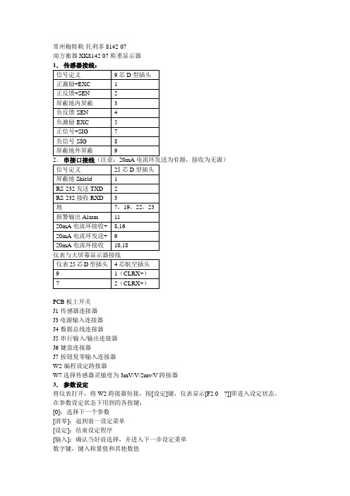
常州梅特勒-托利多8142-07南方衡器XK8142-07称重显示器1.传感器接线:信号定义9芯D型插头正激励+EXC 1正反馈+SEN 2屏蔽地内屏蔽 3负反馈-SEN 4负激励-EXC 5正信号+SIG 7负信号-SIG 8屏蔽地外屏蔽92.串接口接线(注意:20mA电流环发送为有源,接收为无源)信号定义25芯D型插头屏蔽地Shield 1RS-232发送TXD 2RS-232接收RXD 3地7,19,22,23报警输出Alarm 1120mA电流环接收+ 8,1620mA电流环发送+ 920mA电流环接收- 10,18仪表与大屏幕显示器接线仪表25芯D型插头4芯航空插头9 1(CLRX+)7 2(CLRX+)PCB板上开关J1-传感器连接器J3电源输入连接器J4-数据总线连接器J5-串行输入/输出连接器J6-键盘连接器J7-按钮复零输入连接器W2-编程设定跨接器W7选择传感器灵敏度为3mV/V/2mv/V跨接器3.参数设定将仪表打开,将W2跨接器短接,按[设定]键,仪表显示[F2.0 ?]]即进入设定状态。
在参数设定状态下用到的各按键:[0]:选择下一个参数[清零]:退到前一设定菜单[设定]:结束设定程序[输入]:确认当好前选择,并进入下一步设定菜单数字键,键入称量值和其他数值F2应用环境:F2·0·X 皮重功能F2·1·X 皮重功能有效(X=0禁止皮重功能 X=1允许键盘/按钮或远程皮重功能)F2·2·X 皮重锁定(X=0禁止皮重锁定(可去皮和清皮) X=1允许皮重锁定)仪表在毛重状态下才能进行却去皮操作,才能从键盘输入皮重,才能进行清皮操作,皮重锁定状态下,动态时重量光标(kg)不会熄灭,仪表加电后显示[EEE]表示重量大于毛重零,显示[-EEE]表示重量小于毛重零,直到重量等于毛重零才能显示正常重量。
F2·3·X 自动清除皮重(X=0禁止(必须用[清除]手动清除皮重) X=1允许当净重稳定在10 d以上且系统回到毛重零状态时,显示自动回到毛重方式)F2·4·X 零光标功能(X=0零光标只在毛重零时显示 X=1零光标在毛重零净重零时都亮) F2·5 ·1 开机自动清零(X=0禁止 X=1允许)F2·6·2 累计功能(X=0禁止 X=1允许)F2·8 ·1 最小允许累计值[****]为最小允许累计重量对应的分度数F3·0 加电功能((X=0跳过加电功能,进入下一步, X=1进入加电功能和单位选择功能)F3·1 加电预热时间(X=0禁止 X=1允许预热30秒钟,在此期间无重量显示)F3·2 加电重量单位(X=0 kg X=1 lb)F3·3 lb/kg转换(X=0禁止 X=1允许)F3·4 扩展显示(X=0禁止 X=1允许)F3·5·* 量程调整(X=0禁止 X=1允许)F3·6·* 欠载显示(X=0禁止显示大于5d的负重量,只显示[-]号 X=1允许显示5%FS 的负重量)F3·7 零基准调零(X=0禁止 X=1允许有±20%FS毛重零基准调零,并储存新的零基准)F4·0 数字滤波和AZM功能(X=0禁止 X=1允许进入该组设定)F4·1 自动零跟踪阀值(X=0禁止 X=1接受显示的阀值0=无 05=±5d 10=±10d 20=±20d 30=±30d)零跟踪的速率为0.1d/秒F4·2 动态灵敏度F4·3 动态检测次数F4·4 数字滤波(X=0选择下一参数 X=1允许0=无 1=轻度滤波 2=中度滤波 3=较重度滤波4=重度滤波)F4·7 按钮清零范围(X=0禁止 X=1允许)F5· 0 数据输出功能(X=0跳过该组 X=1允许进入该组设定)F5·1 输出方式(X=0无 X=1命令X=2 TOLEDO连续方式 X=3 MASSTRON连续方式) F5·2 数据输出接口选择(X=0JN口为20mA和RS-232通讯接口 X=1RS-422接口)F5·3 波特率(1200/2400/4800/9600)F5·4 校验和选择(X=0选择下一参数 X=1允许)F5·5 打印机选择(X=0选择下一参数 X=1)F5·6 数据输出格式选择日期、时间重量数据累计次数累计和其中重量数据可由X参数X=0:显示重量X=1:单行显示毛重皮重净重X=2:3行显示毛重皮重净重F5·7 字符扩展打印(X=0禁止 X=1允许显示重量被打印成双倍宽字体)F5·8 最小打印重量(X=0选择下一参数 X=1接受显示值1:lb/kg/2:t/3:无符号F5·9 打印重量单位选择(X=0选择下一参数 X=1接受显示值0/10/20/30d可选择) F5·10 负重量打印(X=0禁止 X=1允许)F5·11 重量重复打印(X=0禁止 X=1允许)F5·12 时间/日期功能(X=0禁止 X=1允许时间日期调显示和打印输出)F5·16 皮重/毛重修正功能(X=0禁止 X=1允许皮重大于毛重时自动修正)选择这一功能时,必须禁止F5·11F5·17 ASCII远距离控制功能X=0禁止 X=1允许从JN按受ASCII控制清零、去皮、清除皮重和打印)F5·18 打印内锁(X=0选择下一参数 X=1接受显示值)校正程序:1.短接W2,按[设定]2.按[输入] 直到显示[CAL ?](1=进入校正程序。
托利多8142-0007称重仪表简易说明
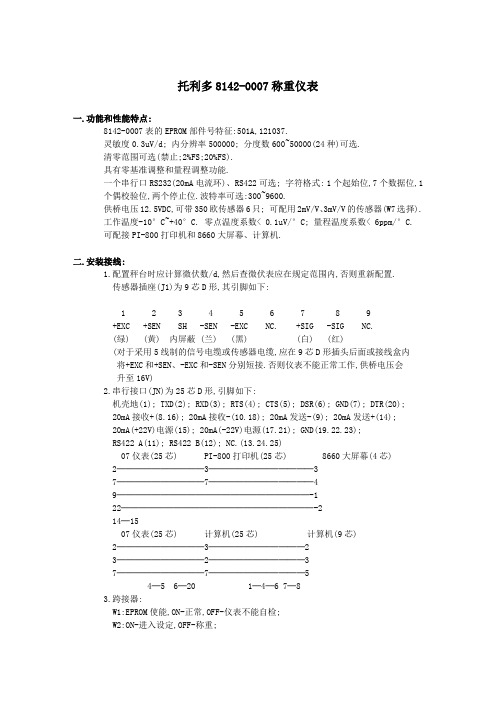
托利多8142-0007称重仪表一.功能和性能特点:8142-0007表的EPROM部件号特征:501A,121037.灵敏度0.3uV/d; 内分辨率500000; 分度数600~50000(24种)可选.清零范围可选(禁止;2%FS;20%FS).具有零基准调整和量程调整功能.一个串行口RS232(20mA电流环)、RS422可选; 字符格式: 1个起始位,7个数据位,1 个偶校验位,两个停止位.波特率可选:300~9600.供桥电压12.5VDC,可带350欧传感器6只; 可配用2mV/V、3mV/V的传感器(W7选择).工作温度-10°C~+40°C. 零点温度系数< 0.1uV/°C; 量程温度系数< 6ppm/°C.可配接PI-800打印机和8660大屏幕、计算机.二.安装接线:1.配置秤台时应计算微伏数/d,然后查微伏表应在规定范围内,否则重新配置.传感器插座(J1)为9芯D形,其引脚如下:1 2 3 4 5 6 7 8 9+EXC +SEN SH -SEN -EXC NC. +SIG -SIG NC.(绿) (黄) 内屏蔽 (兰) (黑) (白) (红)(对于采用5线制的信号电缆或传感器电缆,应在9芯D形插头后面或接线盒内将+EXC和+SEN、-EXC和-SEN分别短接.否则仪表不能正常工作,供桥电压会升至16V)2.串行接口(JN)为25芯D形,引脚如下:机壳地(1); TXD(2); RXD(3); RTS(4); CTS(5); DSR(6); GND(7); DTR(20);20mA接收+(8.16); 20mA接收-(10.18); 20mA发送-(9); 20mA发送+(14);20mA(+22V)电源(15); 20mA(-22V)电源(17.21); GND(19.22.23);RS422 A(11); RS422 B(12); NC.(13.24.25)07仪表(25芯) PI-800打印机(25芯) 8660大屏幕(4芯) 2──────────3────────────37──────────7────────────49──────────────────────-122──────────────────────-214─1507仪表(25芯) 计算机(25芯) 计算机(9芯)2──────────3───────────23──────────2───────────37──────────7───────────54─5 6─20 1─4─6 7─83.跨接器:W1:EPROM使能,ON-正常,OFF-仪表不能自检;W2:ON-进入设定,OFF-称重;W3:ON-逗号,OFF-小数点;W4.W5.W6:不用;W7:1.2.ON-2mV/V,2.3.ON-3mV/V.三.参数设定:用< >表示按键,[ ]表示显示内容.<Setup>:进入设定或跳到[S FILE]; <Entre>:确认并进到下一步; <Zero>:退一步<Clear>:清除; <0>:否定; <1>:肯定.参数说明选择推荐值F2.0 皮重功能组2.1 皮重功能允许 0,1 12.2 皮重内锁 0,1 02.3 自动清皮 0,1 02.4 净重零中心光标 0,1 0F3.0 上电功能组3.1 上电延时 0,1 03.2 上电单位 0,1 03.3 单位转换 0,1 03.4 扩展显示 0,1 03.5 量程调整 0,1 03.6 负重量显示 0,1 13.7 零基准调整 0,1 0F4.0 数字滤波和零跟踪组4.1 零跟踪窗口值 0,05,10,20,30 054.2 动态灵敏度 00~30 074.3 动态检测次数 01~30 034.4 数字滤波 0,1,2,3,4 14.7 清零范围 0-禁止,1-2%,2-20% 1F5.0 数据输出功能组5.1 输出方式 1-命令,2-T连续,3-M连续 15.2 通讯方式 0-232(20mA),1-422 05.3 波特率 300~9600 12005.4 校验和 0,1 05.5 打印机选择 1,2,3,4,5 25.6 数据格式 1-单行,2-单行毛皮净,3-多行毛皮净 25.7 双宽打印 0,1 05.8 最小打印重量 0,10,20,30 05.9 打印单位 1,2,3 15.10 负重量打印 0,1 15.11 重复打印 0,1 05.16 负净重修正 0,1 15.17 遥控输入 0,1 05.18 打印内锁 1-正常,2-内锁,3-自动 1CAL 校正组C1 分度数 600~50000C2 分度因子 1,2,5C3 小数点位置(分度值) 0.0001~200(C1*C3=FS)E SCL 空秤ADD LD 加载E SCL 空秤S FILE 保存参数J2 ON? 断开W2量程调整进入设定-把F3.5设成1-退出设定;进入设定-[CAL AJ]-<1>-输入准确值-<Enter>-显示准确值;进入设定-[CAL AJ]-<0>-把F3.5设成0-退出设定.零基准调整进入设定-对F3.7输入1-退出设定-显示零.若一次调不好,可再进行一次.07表配用PI-800打印机的参数设置(F5.0)如上面最后一列的推荐值.07表配用大屏幕和计算机的参数设置为: F5.1 2;F5.2 0;F5.3 1200;F5.4 0.四.操作索引:< >表示按键,[ ]表示显示内容.<Zreo>:清零; <Tare>:去皮; <Clear>:清除; <Recall>:调显; <Print>:打印;<Enter>-<Tare>:皮重调用; <Test>:自检; <Setup>:设定时间和日期.五.错误代码:E1--ROM出错:1.重新上电; 2.更换PCB板.E2--RAM出错:同上.E3--NOVRAM出错:同上.E4--打印机出错:检查打印机和电缆.E5--显示校验出错:更换PCB板.CAL E1--秤处于动态:重新校正.CAL E2--校正出错:1.重新校正; 2.更换PCB板.CAL E3--同上.CAL E4--秤超载:减少测试重量.CAL E5--配置错误(信号太小):重新配置.CAL E6--测试重量太小:增加测试重量.CAL E8--输入不规范的重量值:重新输入.。
8142Pro单显示仪表技术手册
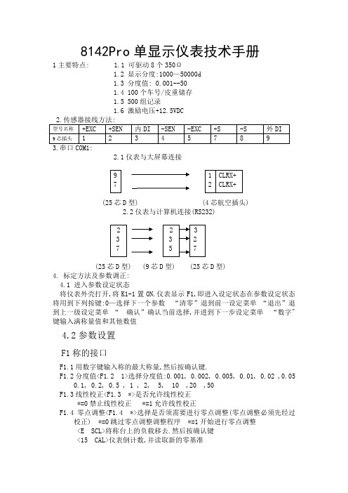
8142Pro单显示仪表技术手册1主要特点: 1.1 可驱动8个350Ω1.2 显示分度:1000—50000d1.3 分度值: 0.001--50100个车号/皮重储存500组记录激励电压+12.5VDC2.1仪表与大屏幕连接9 1 CLRX+7 2 CLRX+(25芯D型) (4芯航空插头)2.2仪表与计算机连接(RS232)2 2 33 3 27 5 7(25芯D型) (9芯D型) (25芯D型)4. 标定方法及参数调正:4.1 进入参数设定状态将仪表外壳打开,将K1-1置ON.仪表显示F1,即进入设定状态在参数设定状态将用到下列按键:0—选择下一个参数“清零”退到前一设定菜单“退出”退到上一级设定菜单“确认”确认当前选择,并进到下一步设定菜单“数字"键输入满称量值和其他数值4.2参数设置F1称的接口F1.1用数字键输入称的最大称量,然后按确认键.F1.2分度值<F1.2 1>选择分度值:0.001, 0.002, 0.005, 0.01, 0.02 ,0.050.1, 0.2, 0.5 , 1 , 2, 5, 10 ,20 ,50F1.3线性校正<F1.3 *>是否允许线性校正*=0禁止线性校正 *=1允许线性校正F1.4零点调整<F1.4 *>选择是否须需要进行零点调整(零点调整必须先经过校正) *=0跳过零点调整调整程序 *=1开始进行零点调整<E SCL>将称台上的负载移去.然后按确认键<15 CAL>仪表倒计数,并读取新的零基准F1.5量程(Span)调整.将标准重量放在称台上,而后进入设定状态,进到F1.5=1,进行量程调整.<F1.5 *>选择是否需要进行量程调整量程调整前必须经过标准校正)*=0跳过量程调整程序 *=1开始进行量程调整<Add Ld>加载< 00000>用数字键输入称台上所加重量值<15 CAL>仪表倒计数,并读取新的满量程值<F1.6 *>校正<F1.6 *>称的校正 *=0跳过校正程序 *=1进入校正程序F1.3=0时(无线形校正)<E SCL>将负载从称台上移去,然后按确认键<15 SCL>仪表倒记数,并读取满量程值.<Add Ld>加载< 00000>用数字键输入所加重量值<15 CAL>仪表倒记数,并读取称量值<CAL d>校正完成.仪表显示<F1.7 0><F1.3=1时(有线性校正)<E SCL >将负载从称台上移去,然后按确认键<15 CAL>仪表倒记数,并读取空称值<Add Hi>加载< 00000>用数字键输入所加重量值<15 CAL>仪表倒记数,并读取高端值<Add Lo>加载< 00000>用数字键输入所加重量值<15 CAL>仪表倒记数,并读取低端值<CAL d>校正完成.仪表显示<F1.7 0>F1.7扩展显示<F1.7 *>设置扩展显示.扩展显示时仪表读书为显示分度数*10*=0正常显示 *=1扩展显示F2 应用环境F2.1 开机延时<F2.1 *>设置开机预热时间:0-无开机延时 1-延时10分钟2-延时20分钟 3-延时10分钟F2.2 零点操作<F2.2.1 *>设置开机自动清零范围*=禁止开机自动清零 *=1开机清零范围为±2%满称量*=2开机清零范围为±20%满称量<F2.2 *>设置按键清零范围 *=0禁止按键清零*=1按键清零范围为±2%满称量*=2按键清零范围为±20%满称量<F2.3 *>自动零点跟踪 *=0禁止零跟踪功能*=1自动零点跟踪值为±0.5d *=2自动零点跟踪值为±1.0d*=3自动零点跟踪值为±3.0dF2.3皮重操作<F2.3.1 *>皮重功能 *=1禁止皮重功能 *=2允许皮重功能<F2.3.2 *>皮重内锁功能 *=0禁止皮重内锁功能*=1允许皮重内锁功能<F2.3.3 *>自动去皮 *=0禁止自动去皮*=1允许自动去皮,在毛重零状态下若重量大于5d且称处于稳态,则自动去皮<F2.3.4 *>自动清皮 *=0禁止自动清皮*=1允许自动清皮,在毛重零状态将自动清皮<F2.3.5 *>键盘皮重功能 *=0禁止用数字键盘输入皮重值*=1允许用数字键盘输入皮重值F2.4动态范围<F2.4 *>动态范围 *=0禁止动态检测 *=1动态范围为±1.0d*=2动态范围为±3.0dF2.5数字滤波<F2.5 2.5>设置低通滤波器截止频率输入2位数的频率值.输入范围为0.5-9.9,数字越小滤波越重,显示更新速率越慢<F2.5.1 *>噪声滤波器 *=0禁止噪声滤波器(在系统应用中应选0)*=1允许噪声滤波器F3 串行口Com1设置F3.1波特率<F3.1 >选择波特率:300 1200 2400 4800 9600F3.2数据位<F3.2>选择数据位 *=7数据位为7bits *=8数据位为8bitsF3.3效验位<F3.3 *>选择效验位 *=0 None无效验 *=1 0dd奇效验*=2 Even偶效验F3.4 效验和<F3.4 *选择效验和字符 *=0不发送效验和字符*=1发送效验和字符F3.5输出方式<F3.5 *>输出方式 *=0无输出 *=1连续输出方式 *=2命令输出方式F3.6单字符命令输入<F3.6 *>单字符ASCII命令输入 *=0禁止 *=1 允许ASCII命令输入ASCII命令输入:Z-清零T-去皮D-清皮P-打印F5并行口设置<F5.1 *>打印机选则 *=0PQ30称重打印机*=1 EPSON LQ300K. EPSON 1600K,LQ2500K*=2 Tpup微打(只能串口输出,接COM1口*=3Times TM800,Panisonic KX-P1121F5.2打印格式选择F5.3输入打印表头<F5.3 *>用区位码输入计量单表头,最多15个汉字.可以在各报表的开始打印表头.选1允许打印表头并进入汉字输入状态.仪表首先显示当前所显示字符的位置,然后显示4位数字的区位码.输入4位数后按确认键后自动进入下一字符.F5.4,自动打印<F5.4 *>自动打印允许选1允许自动打印并进入自动打印设置状态.自动打印时,有关时间,日期,序号及重量数据将自动存储.<F5.4.1 >输入自动打印值<F5.4.2 >输入自动打印复位值F6操作设置F6.1车号/皮重存储功能<F6.1 *>车号/皮重存储功能 *=0禁止车号/皮重存储功能*=1允许车号/皮重存储功能F6.5报警输出*=0禁止报警输出 *=1允许报警输出选1允许报警输出并进入报警输出极性设置状态<F6.5.1 *>报警输出极性 *=0低于报警值时输出为低电平,高于报警值时输出为高电平 *=1低于报警值时输出为高电平,高于报警值时输出为低电平F7自诊断<F7.1 0>存储器测试选1则开始进行存储器测试.仪表显示器全亮,然后显示仪表版本号.F7.3键盘测试<F7.3 0>键盘测试选1则开始进行键盘测试仪表将显示你所按的键值.按退出键退出F7.4称的校正参数<F7.4 0>零点读数选1后按确认键,显示器显示<FinEO>两秒种后显示零点读数按确认键,显示器显示<SPA1>两秒种然后显示量程系数高端部分.按确认键,显示器显示<SPA2>两秒种然后显示量程系数低端部分. F7.5串行口测试<F7.5.1 0>Com1测试将串行口的Com1和RXD短接, 选1则开始进行测试,仪表开始从1-99记数,显示器左2位显示从串行口发出的数据, 显示器右2位显示从串行口接收的数据.两者相等即正常.F7.6并行口测试<F7.6 0>并行口测试将并行口与打印机连接, 选1则开始进行测试,打印机将打印下列内容:打印口测试完成Parllel Port Test Complete 否则仪表显示出错信息F7.7打印设定参数<F7.7 O>打印设定参数将并行口与打印机连接,选1则开始打印设定参数.F7.8设置工厂缺省值<F7.8 0>设定参数回到工厂缺省值选1仪表显示LoAd 0,按0键仪表显示LoAd 1,然后按确认键,则设定参数. 回到工厂缺省值4.3退出参数设定状态按退出键.仪表显示<CAL OFF>按确认键确认, 仪表显示<1-1 Off>将仪表外壳打开,将K1-1置OFF.仪表自动回到正常显示状态。
XK8142-07C仪表说明书 2008-02-28
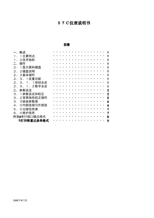
一.概述11.1主要特点11.2技术指标1二.操作12.1显示器和键盘12.2键盘说明12.3基本操作12.3.1皮重功能12.3.1.1按钮去皮12.3.1.2数字去皮1三.参数设定23.1参数设定和校正23.2简易线性校正操作53. 3缺省参数值64.0内部连接与外部连接65.0出错信息表76.0维护保养7附录A 串行接口输出格式8 B 打印称重记录单格式92008年9月版·························································································································································目录·····················································································07C仪表说明书·····················································································一.概述1.1 主要特点·1个6位VFD显示屏·16键薄膜键盘·显示分度数:1000~50000可选·显示分度值:0.001~50·高精度,高分辨率∑-△型A/D转换器·最大A/D脉冲数:4,000,000·可驱动10个350欧姆的模拟式传感器·自动零跟踪·动态检测·数字滤波·采用全铝合金外壳及电源滤波器,抗干扰性能强,能应用到各种复杂的工作环境·串行通讯接口:RS-232·超载显示,及各种错误信息显示1.2技术指标·激励电压:DC+10V,最多可驱动10个350欧姆模拟传感器·输入信号:5~30mv·零点信号:0~20mv·电源电压:~187~242V,50HZ·使用环境:温度0~40℃,湿度10~95%·串行通讯口:RS-232 波特率选择范围:1200,2400,4800,9600·超载显示范围:9d·功率:15W·保险丝:0.5A二.操作2.1 显示器与键盘说明2.1.1 显示器面板光标说明零位光标:当秤处于零的±1/4d之间时,此光标亮。
8142称重显示仪
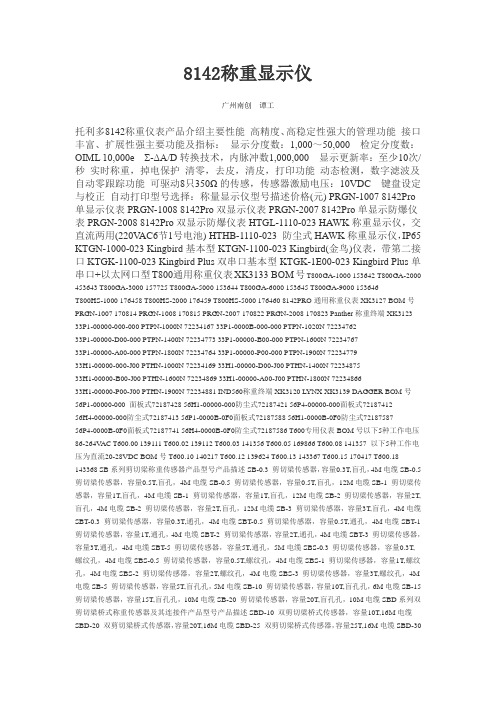
8142称重显示仪广州南创谭工托利多8142称重仪表产品介绍主要性能高精度、高稳定性强大的管理功能接口丰富、扩展性强主要功能及指标:显示分度数:1,000~50,000 检定分度数:OIML 10,000e Σ-ΔA/D转换技术,内脉冲数1,000,000 显示更新率:至少10次/秒实时称重,掉电保护清零,去皮,清皮,打印功能动态检测,数字滤波及自动零跟踪功能可驱动8只350Ω的传感,传感器激励电压:10VDC 键盘设定与校正自动打印型号选择:称量显示仪型号描述价格(元) PRGN-1007 8142Pro 单显示仪表PRGN-1008 8142Pro双显示仪表PRGN-2007 8142Pro单显示防爆仪表PRGN-2008 8142Pro双显示防爆仪表HTGL-1110-023 HAWK称重显示仪,交直流两用(220V AC6节1号电池) HTHB-1110-023 防尘式HAWK称重显示仪,IP65 KTGN-1000-023 Kingbird基本型KTGN-1100-023 Kingbird(金鸟)仪表,带第二接口KTGK-1100-023 Kingbird Plus双串口基本型KTGK-1E00-023 Kingbird Plus单串口+以太网口型T800通用称重仪表XK3133 BOM号T800GA-1000 153642 T800GA-2000 453643 T800GA-3000 157725 T800GA-5000 153644 T800GA-6000 153645 T800GA-9000 153646T800HS-1000 176458 T800HS-2000 176459 T800HS-5000 176460 8142PRO通用称重仪表XK3127 BOM号PRGN-1007 170814 PRGN-1008 170815 PRGN-2007 170822 PRGN-2008 170823 Panther称重终端XK3123 33P1-00000-000-000 PTPN-1000N 72234167 33P1-0000B-000-000 PTPN-1020N 7223476233P1-00000-D00-000 PTPN-1400N 72234773 33P1-00000-B00-000 PTPN-1600N 7223476733P1-00000-A00-000 PTPN-1800N 72234764 33P1-00000-P00-000 PTPN-1900N 7223477933H1-00000-000-J00 PTHN-1000N 72234169 33H1-00000-D00-J00 PTHN-1400N 7223487533H1-00000-B00-J00 PTHN-1600N 72234869 33H1-00000-A00-J00 PTHN-1800N 7223486633H1-00000-P00-J00 PTHN-1900N 72234881 IND560称重终端XK3120 LYNX XK3139 DAGGER BOM号56P1-00000-000 面板式72187428 56H1-00000-000防尘式72187421 56P4-00000-000面板式7218741256H4-00000-000防尘式72187413 56P1-0000B-0F0面板式72187588 56H1-0000B-0F0防尘式7218758756P4-0000B-0F0面板式72187741 56H4-0000B-0F0防尘式72187586 T600专用仪表BOM号以下5种工作电压86-264V AC T600.00 139111 T600.02 139112 T600.03 141356 T600.05 169866 T600.08 141357 以下5种工作电压为直流20-28VDC BOM号T600.10 140217 T600.12 139624 T600.13 143367 T600.15 170417 T600.18 143368 SB系列剪切梁称重传感器产品型号产品描述SB-0.3 剪切梁传感器,容量0.3T,盲孔,4M电缆SB-0.5 剪切梁传感器,容量0.5T,盲孔,4M电缆SB-0.5 剪切梁传感器,容量0.5T,盲孔,12M电缆SB-1 剪切梁传感器,容量1T,盲孔,4M电缆SB-1 剪切梁传感器,容量1T,盲孔,12M电缆SB-2 剪切梁传感器,容量2T,盲孔,4M电缆SB-2 剪切梁传感器,容量2T,盲孔,12M电缆SB-3 剪切梁传感器,容量3T,盲孔,4M电缆SBT-0.3 剪切梁传感器,容量0.3T,通孔,4M电缆SBT-0.5 剪切梁传感器,容量0.5T,通孔,4M电缆SBT-1 剪切梁传感器,容量1T,通孔,4M电缆SBT-2 剪切梁传感器,容量2T,通孔,4M电缆SBT-3 剪切梁传感器,容量3T,通孔,4M电缆SBT-5 剪切梁传感器,容量5T,通孔,5M电缆SBS-0.3 剪切梁传感器,容量0.3T,螺纹孔,4M电缆SBS-0.5 剪切梁传感器,容量0.5T,螺纹孔,4M电缆SBS-1 剪切梁传感器,容量1T,螺纹孔,4M电缆SBS-2 剪切梁传感器,容量2T,螺纹孔,4M电缆SBS-3 剪切梁传感器,容量3T,螺纹孔,4M 电缆SB-5 剪切梁传感器,容量5T,盲孔孔,5M电缆SB-10 剪切梁传感器,容量10T,盲孔孔,6M电缆SB-15 剪切梁传感器,容量15T,盲孔孔,10M电缆SB-20 剪切梁传感器,容量20T,盲孔孔,10M电缆SBD系列双剪切梁桥式称重传感器及其连接件产品型号产品描述SBD-10 双剪切梁桥式传感器,容量10T,16M电缆SBD-20 双剪切梁桥式传感器,容量20T,16M电缆SBD-25 双剪切梁桥式传感器,容量25T,16M电缆SBD-30SBD-30(B) G 双剪切梁桥式传感器,容量30T,16M电缆SBD-40 双剪切梁桥式传感器,容量40T,16M电缆SBD-50 双剪切梁桥式传感器,容量50T,16M电缆连接件QP 76钢球YP 钢球压头SBC系列紧密型剪切梁称重传感器及其连接件产品型号产品描述SBC-0.5 紧密型剪切梁传感器,容量0.5T,3M电缆SBC-0.5 紧密型剪切梁传感器,容量0.5T,6M电缆SBC-1 紧密型剪切梁传感器,容量1T,3M电缆SBC-1 紧密型剪切梁传感器,容量1T,6M电缆SBC-2 紧密型剪切梁传感器,容量2T,3M电缆SBC-2 紧密型剪切梁传感器,容量2T,6M电缆SBC-3 紧密型剪切梁传感器,容量3T,3M电缆SBC-3 紧密型剪切梁传感器,容量3T,6M电缆SBH系列不锈钢焊接密封传感器产品型号产品描述SBH-0.25 弯曲梁称重传感器,称重容量0.25T,承载孔为盲孔,5M电缆SBH-0.5 弯曲梁称重传感器,称重容量0.5T,承载孔为盲孔,5M电缆SBH-1 弯曲梁称重传感器,称重容量1T,承载孔为盲孔,5M电缆SBH-2 弯曲梁称重传感器,称重容量2T,承载孔为盲孔,5M电缆SBH-3 弯曲梁称重传感器,称重容量3T,承载孔为盲孔,5M电缆SBH-5 弯曲梁称重传感器,称重容量5T,承载孔为盲孔,5M电缆TSH不锈钢焊接密封拉式传感器产品型号额定容量TSH-200KG200KG,5M电缆TSH-300KG 300KG,5M电缆TSH-500KG 500KG,5M电缆TSH-1T 1T,5M电缆TSH-2T 2T,5M 电缆TSH-3T 3T,5M电缆TSH-5T 5T,5M电缆SSH系列不锈钢焊接密封传感器产品型号额定容量SSH-50KG 传感器50KG,2.5M电缆SSH-100KG传感器100KG,2.5M电缆SSH-200KG传感器200KG,2.5M电缆SSH-300KG传感器300KG,2.5M电缆SSH-500KG传感器500KG,2.5M电缆SSH-1000KG传感器1000KG,2.5M 电缆IL系列称重传感器产品型号产品描述IL-150 钢质弯曲梁传感器,容量150KG,2.5M电缆IL-250 钢质弯曲梁传感器,容量250KG,2.5M电缆IL-500 钢质弯曲梁传感器,容量500KG,2.5M电缆IL-1000 钢质弯曲梁传感器,容量1000KG,2.5M电缆IL-2000 钢质弯曲梁传感器,容量2000KG,2.5M电缆SBF系列轮辐式称重传感器产品型号额定容量SBF-2.25 2.25T(5K),10M电缆SBF-4.5 4.5T(10K),10M电缆SBF-11.2511.25T(25K),10M电缆SBF-22.5 22.5T(50K),10M电缆SBF-45 45T(100K),10M电缆MT系列称重传感器产品型号产品描述MT1022-3 单点式铝质弯曲梁传感器MT1022,容量3KG,1M电缆MT1022-5 单点式铝质弯曲梁传感器MT1022,容量5KG,1M电缆MT1022-7 单点式铝质弯曲梁传感器MT1022,容量7KG,1M电缆MT1022-10 单点式铝质弯曲梁传感器MT1022,容量10KG,1M电缆MT1022-15 单点式铝质弯曲梁传感器MT1022,容量15KG,1M电缆MT1022-20 单点式铝质弯曲梁传感器MT1022,容量20KG,1M电缆MT1022-30 单点式铝质弯曲梁传感器MT1022,容量30KG,1M电缆MT1041-10 单点式铝质弯曲梁传感器MT1041,容量10KG,2M电缆MT1041-15 单点式铝质弯曲梁传感器MT1041,容量15KG,2M电缆MT1041-20 单点式铝质弯曲梁传感器MT1041,容量20KG,2M电缆MT1041-30 单点式铝质弯曲梁传感器MT1041,容量30KG,2M电缆MT1041-50 单点式铝质弯曲梁传感器MT1041,容量50KG,2M电缆MT1041-75 单点式铝质弯曲梁传感器MT1041,容量75KG,2M电缆MT1041-100 单点式铝质弯曲梁传感器MT1041,容量100KG,2M电缆MT1241-30 单点式铝质弯曲梁传感器MT1241,容量30KG,2M电缆MT1241-50 单点式铝质弯曲梁传感器MT1241,容量50KG,2M电缆MT1241-100 单点式铝质弯曲梁传感器MT1241,容量100KG,2M电缆MT1241-150 单点式铝质弯曲梁传感器MT1241,容量150KG,2M电缆MT1241-200 单点式铝质弯曲梁传感器MT1241,容量200KG,2M电缆MT1241-250 单点式铝质弯曲梁传感器MT1241,容量250KG,2M电缆MT1260-50 单点式铝质弯曲梁传感器MT1260,容量50KG,2M电缆MT1260-75 单点式铝质弯曲梁传感器MT1260,容量75KG,2M电缆MT1260-100 单点式铝质弯曲梁传感器MT1260,容量100KG,2M电缆MT1260-150 单点式铝质弯曲梁传感器MT1260,容量150KG,2M电缆MT1260-200 单点式铝质弯曲梁传感器MT1260,容量200KG,2M电缆MT1260-250 单点式铝质弯曲梁传感器MT1260,容量250KG,2M电缆MT1260-300 单点式铝质弯曲梁传感器MT1260,容量300KG,2M电缆MT1260-500 单点式铝质弯曲梁传感器MT1260,容量500KG,2M电缆MT1260-635 单点式铝质弯曲梁传感器MT1260,容量635KG,2M电缆MT1260-750 单点式铝质弯曲梁传感器MT1260,容量750KG,2M电缆MTB系列称重传感器产品型号产品描述MTB-5 单点式波纹管焊接密封不锈钢传感器,容量5KG,3M电缆MTB-10 单点式波纹管焊接密封不锈钢传感器,容量10KG,3M电缆MTB-20 单点式波纹管焊接密封不锈钢传感器,容量20KG,3M电缆MTB-30 单点式波纹管焊接密封不锈钢传感器,容量30KG,3M电缆MTB-50 单点式波纹管焊接密封不锈钢传感器,容量50KG,3M电缆MTB-50 单点式波纹管焊接密封不锈钢传感器,容量50KG,8M电缆MTB-75 单点式波纹管焊接密封不锈钢传感器,容量75KG,3M电缆MTB-100 单点式波纹管焊接密封不锈钢传感器,容量100KG,3M电缆MTB-100 单点式波纹管焊接密封不锈钢传感器,容量100KG,8M电缆MTB-200 单点式波纹管焊接密封不锈钢传感器,容量200KG,3M电缆MTB-200 单点式波纹管焊接密封不锈钢传感器,容量200KG,8M电缆MTB-300 单点式波纹管焊接密封不锈钢传感器,容量300KG,3M电缆MTB-300 单点式波纹管焊接密封不锈钢传感器,容量300KG,8M电缆MTB-500 单点式波纹管焊接密封不锈钢传感器,容量500KG,3M电缆TSC/TSB拉式称重传感器产品型号产品描述TSC-50 钢质拉式传感器,容量50KG,5M电缆TSC-100 钢质拉式传感器,容量100KG,5M电缆TSC-200 钢质拉式传感器,容量200KG,5M电缆TSC-300 钢质拉式传感器,容量300KG,5M电缆TSC-500 钢质拉式传感器,容量500KG,5M电缆TSC-1000 钢质拉式传感器,容量1000KG,5M电缆TSB-2000 钢质拉式传感器,容量2000KG,5M电缆TSB-2000 钢质拉式传感器,容量2000KG,12M电缆TSB-3000 钢质拉式传感器,容量3000KG,5M电缆TSB-3000 钢质拉式传感器,容量3000KG,12M电缆TSB-5000 钢质拉式传感器,容量5000KG,5M电缆TSB-5000 钢质拉式传感器,容量5000KG,12M电缆拉式称重传感器连接件产品型号产品描述TP-100~300 配100~300KG TSC,拉杆式TP-500~1000 配500~1000KG TSC,拉杆式ZP-100~300 配100~300KG TSC,关节轴承式ZP-500~1000配500~1000KG TSC,关节轴承式ZP-2000 配2000KG TSB,关节轴承式ZP-3000 配3000KG TSB,关节轴承式ZP-5000 配5000KG TSB,关节轴承式GD摇柱式称重传感器产品型号产品描述GD-15T GD摇柱式称重传感器,容量15T,13M电缆GD-20T GD摇柱式称重传感器,容量20T,13M电缆GD-30T GD摇柱式称重传感器,容量30T,13M电缆GD-50T GD摇柱式称重传感器,容量50T,13M电缆GD-100T GD摇柱式称重传感器,容量100T,13M电缆GD-200T GD摇柱式称重传感器,容量200T,20M电缆GD-250T GD摇柱式称重传感器,容量250T,20M电缆GD-300T GD摇柱式称重传感器,容量300T,30M电缆GD-400T GD摇柱式称重传感器,容量400T,30M电缆GD-500T GD摇柱式称重传感器,容量500T,30M电缆GD系列传感器连接件产品型号产品描述CP GD连接件CP(15~50T) DP GD连接件DP(15~50T) CP(100T) GD连接件CP(100T) DP(100T) GD连接件DP(100T) PGD系列柱式称重传感器产品型号产品描述PGD-2 PGD柱式传感器,容量2T,13M电缆PGD-5 PGD柱式传感器,容量5T,13M电缆PGD-10 PGD柱式传感器,容量10T,13M电缆PGD-20 PGD 柱式传感器,容量20T,13M电缆PGD-30 PGD柱式传感器,容量30T,13M电缆PGD-50 PGD柱式传感器,容量50T,13M电缆PGD系列传感器连接件产品型号产品描述PP-2~10T PGD柱式传感器专用连接件PP-20~50T PGD柱式传感器专用连接件0745A/0743系列不锈钢焊接密封传感器产品型号产品描述0745A-0.22 0745A称重传感器0.22T,2.2M电缆0745A-0.22 0745A称重传感器0.22T,4.5M电缆0745A-0.22 0745A称重传感器0.22T,9M电缆0745A-0.55 0745A称重传感器0.55T,2.2M电缆0745A-0.55 0745A称重传感器0.55T,4.5M电缆0745A-0.55 0745A称重传感器0.55T,9M电缆0745A-1.1 0745A称重传感器1.1T,2.2M电缆0745A-1.1 0745A称重传感器1.1T,4.5M电缆0745A-1.1 0745A称重传感器1.1T,9M电缆0745A-2.2 0745A称重传感器2.2T,2.2M电缆0745A-2.2 0745A称重传感器2.2T,4.5M电缆0745A-2.2 0745A称重传感器2.2T,9M电缆0745A-4.4 0745A称重传感器4.4T,4.5M电缆0745A-4.4 0745A称重传感器4.4T,9M电缆0745A-4.4 0745A称重传感器4.4T,18M电缆0743-9 0743称重传感器9T,4.5M电缆0743-9 0743称重传感器9T,9M电缆0743-9 0743称重传感器9T,18M电缆0743-13.6 0743称重传感器13.6T,4.5M电缆0743-13.6 0743称重传感器13.6T,9M 电缆0743-13.6 0743称重传感器13.6T,18M电缆0743-20 0743称重传感器20T,4.5M电缆0743-20 0743称重传感器20T,9M电缆0743-20 0743称重传感器20T,18M电缆FW/CW系列称重模块产品型号产品描述FW-0.3 固定式载模块,容量0.3t,4M电缆FW-0.3 半浮动式静载模块,容量0.3t,4M电缆FW-0.3 全浮动式静载模块,容量0.3t,4M电缆FW-0.5 固定式载模块,容量0.5t,4M电缆FW-0.5 半浮动式静载模块,容量0.5t,4M电缆FW-0.5 全浮动式静载模块,容量0.5t,4M电缆FW-1 固定式静载模块,容量1t,4M电缆FW-1 固定式静载模块,容量1t,12M电缆FW-1 半浮动式静载模块,容量1t,4M电缆FW-1 半浮动式静载模块,容量1t,12M电缆FW-1 全浮动式静载模块,容量1t,4M电缆FW-1 全浮动式静载模块,容量1t,12M电缆FW-2 固定式静载模块,容量2t,4M 电缆FW-2 固定式静载模块,容量2t,12M电缆FW-2 半浮动式静载模块,容量2t,4M电缆FW-2 半浮动式静载模块,容量2t,12M电缆FW-2 全浮动式静载模块,容量2t,4M电缆FW-2 全浮动式静载模块,容量2t,12M电缆FW-3 固定式静载模块,容量3t,4M电缆FW-3 半浮动式静载模块,容量3t,4M电缆FW-3 全浮动式静载模块,容量3t,4M电缆FW-5 固定式静载模块,容量5t,5M电缆FW-5 半浮动式静载模块,容量5t,5M电缆FW-5 全浮动式静载模块,容量5t,5M电缆FW-10 固定式静载模块,容量10t,6M电缆FW-10 半浮动式静载模块,容量10t,6M电缆FW-10 全浮动式静载模块,容量10t,6M电缆FW-15 固定式静载模块,容量15t,10M电缆FW-15 半浮动式静载模块,容量15t,10M电缆FW-15 全浮动式静载模块,容量15t,10M电缆FW-20 固定式静载模块,容量20t,10M电缆FW-20 半浮动式静载模块,容量20t,10M电缆FW-20 全浮动式静载模块,容量20t,10M电缆UW-5 UW不锈钢称重模块,容量5kg,,3M电缆UW-10 UW不锈钢称重模块,容量10kg,,3M电缆UW-20 UW不锈钢称重模块,容量20kg,,3M电缆UW-50 UW不锈钢称重模块,容量50kg,,3M电缆UW-75 UW不锈钢称重模块,容量75kg,,3M电缆UW-100 UW不锈钢称重模块,容量100kg,,3M电缆UW-100 UW不锈钢称重模块,容量100kg,,8M电缆UW-200 UW不锈钢称重模块,容量200kg,,3M电缆UW-200 UW不锈钢称重模块,容量200kg,,8M电缆UW-300 UW不锈钢称重模块,容量300kg,,3M电缆UW-500 UW不锈钢称重模块,容量500kg,,3M电缆。
托利多8142说明书