I-PEX20634-112T-02 TO HRS DF19-30S-1SD CONN or CABLE
和谐XPS安全自动化产品数据表说明书

Product data sheetSpecificationsTime delayed output, Harmony XPS,for Estop, guard, OSSD, 24 V AC/DC, springXPSBAT12A1ACMainRange of ProductHarmony Safety Automation Product or Component Type Safety module Safety module name XPSBATSafety module application For emergency stop and protective guard applications For OSSD monitoringFunction of moduleEmergency stop button with 2 NC contacts Guard monitoring with 1 or 2 limit switches Light curtain monitoring RFID switchMonitoring of electro-sensitive protection equipment (ESPE)Safety levelCan reach PL e/category 4 for normally open relay contact ISO 13849-1Can reach SILCL 3 for normally open relay contact IEC 62061Can reach SIL 3 for normally open relay contact IEC 61508Can reach PL c/category 1 for normally closed relay contact ISO 13849-1Can reach SILCL 1 for normally closed relay contact IEC 62061Can reach SIL 1 for normally closed relay contact IEC 61508Safety reliability dataMTTFd > 30 years ISO 13849-1Dcavg >= 99 % ISO 13849-1PFHd = 0.98E-09 for SS0 ISO 13849-1PFHd = 0.96E-09 for SS1 ISO 13849-1HFT = 1 IEC 62061PFHd = 0.98E-09 for SS0 IEC 62061PFHd = 0.96E-09 for SS1 IEC 62061SFF > 99% IEC 62061HFT = 1 IEC 61508-1PFHd = 0.98E-09 for SS0 IEC 61508-1PFHd = 0.96E-09 for SS1 IEC 61508-1SFF > 99% IEC 61508-1Type = B IEC 61508-1Electrical circuit type NC pair OSSD pairConnections - terminalsRemovable spring terminal block, 0.2...2.5 mm² solid or flexibleRemovable spring terminal block, 0.25...2.5 mm² flexible with ferrule single conductor Removable spring terminal block, 0.2...1.5 mm² solid or flexible twin conductorRemovable spring terminal block, 2 x 0.25...1 mm² flexible with ferrule without cable end, with bezel Removable spring terminal block, 2 x 0.5...1.5 mm² flexible with ferrule with cable end, with bezel [Us] Rated Supply Voltage24 V AC - 15...10 %24 V DC - 20...20 %ComplementarySynchronisation time between inputs 0.5 s 2 sType of startAutomatic/manual/monitored Power consumption in W2 W 24 V DCD i s c l a i m e r : T h i s d o c u m e n t a t i o n i s n o t i n t e n d e d a s a s u b s t i t u t e f o r a n d i s n o t t o b e u s e d f o r d e t e r m i n i n g s u i t a b i l i t y o r r e l i a b i l i t y o f t h e s e p r o d u c t s f o r s p e c i f i c u s e r a p p l i c a t i o n sPower consumption in VA5 VA 24 V AC 50/60 HzInput protection type Internal, electronicSafety outputs 2 NO1 NOSafety inputs2Maximum wire resistance500 OhmTime delay range0...900 sInput compatibility Normally closed circuit ISO 14119Mechanical contact ISO 14119OSSD pair IEC 61496-1-2Normally closed circuit ISO 138503-wire proximity sensors PNP[Ie] rated operational current5 A AC-13 A AC-155 A DC-13 A DC-13Control outputs 3 pulsed outputInput/Output type Semiconductor output Z1, 20 mA[Ith] conventional free air12 Athermal currentAssociated fuse rating6 A gG NO relay output circuit IEC 60947-1 Minimum output current20 mA relay outputMinimum output voltage24 V relay outputMaximum response time on20 msinput open[Ui] rated insulation voltage250 V 2)EN/IEC 60947-1[Uimp] rated impulse withstand4 kV II EN/IEC 60947-1voltageLocal signalling LED green power power ONLED red error errorLED yellow state 1 safety output instantaneousLED yellow state 2 safety output delayedLED yellow start 1 startLED yellow start 2 startLED yellow S12 safety input S12LED yellow S22 safety input S22Mounting Support35 mm symmetrical DIN railDepth 4.72 in (120 mm)Height 3.94 in (100 mm)Width 1.77 in (45 mm)Net Weight0.77 lb(US) (0.350 kg)EnvironmentStandards IEC 60947-5-1IEC 61508-1 functional safety standardIEC 61508-2 functional safety standardIEC 61508-3 functional safety standardIEC 61508-4 functional safety standardIEC 61508-5 functional safety standardIEC 61508-6 functional safety standardIEC 61508-7 functional safety standardISO 13849-1 functional safety standardIEC 62061 functional safety standardProduct certifications TÜVcULusIP degree of protection IP20 terminals)EN/IEC 60529IP40 housing)EN/IEC 60529IP54 mounting area)EN/IEC 60529 Ambient air temperature for-13…131 °F (-25…55 °C)operationAmbient Air Temperature for-13…185 °F (-25…85 °C)StorageRelative Humidity5…95 % non-condensingOrdering and shipping detailsCategory22477-SAFETY MODULES (PREVENTA)Discount Schedule SAF2GTIN3606482034037Nbr. of units in pkg.1Package weight(Lbs)10.65 oz (302 g)Returnability NoPacking UnitsUnit Type of Package 1PCEPackage 1 Height 2.52 in (6.4 cm)Package 1 width 5.24 in (13.3 cm)Package 1 Length 6.02 in (15.3 cm)Unit Type of Package 2S03Number of Units in Package 216Package 2 Weight11.92 lb(US) (5.409 kg)Package 2 Height11.81 in (30 cm)Package 2 width11.81 in (30 cm)Package 2 Length15.75 in (40 cm)Package 3 Height11.81 in (30 cm)Offer SustainabilitySustainable offer status Green Premium productCalifornia proposition 65WARNING: This product can expose you to chemicals including: Lead and lead compounds, which isknown to the State of California to cause cancer and birth defects or other reproductive harm. For moreinformation go to REACh Regulation REACh DeclarationEU RoHS Directive Pro-active compliance (Product out of EU RoHS legal scope)EU RoHS DeclarationMercury free YesRoHS exemption information YesChina RoHS Regulation China RoHS declarationEnvironmental Disclosure Product Environmental ProfileCircularity Profile End of Life InformationWEEE The product must be disposed on European Union markets following specific waste collection andnever end up in rubbish bins.Dimensions Drawings DimensionsFront and Side Views(A) : Product drawing(B) : Spring terminal(C) : Side view(1) : Removable terminal blocks, top(2) : Removable terminal blocks, bottom(3) : LED indicators(4) : Delay factor selector(5) : Delay base selector(6) : Sealable transparent coverMounting to DIN railScrew-mountingConnections and SchemaWiring Diagram(1) : A1-A2 (Power supply)(2) : S11–S21 (Control outputs (DC+) of safety-related inputs), S12-S22 (Input channels (CH+) of safety-related inputs)(3) : Y1 (Control output of Start/Restart input), Y2 (Input channel for automatic/manual start), Y3 (Input channel for monitored start with falling edge)13-14-23-24 : Terminals of the safety-related outputs (instantaneous)37-38 : Terminals of the safety-related outputs (delayed)Z1 : Solid state output, not safety-related。
柔性检查作用域套件-USB 产品说明书
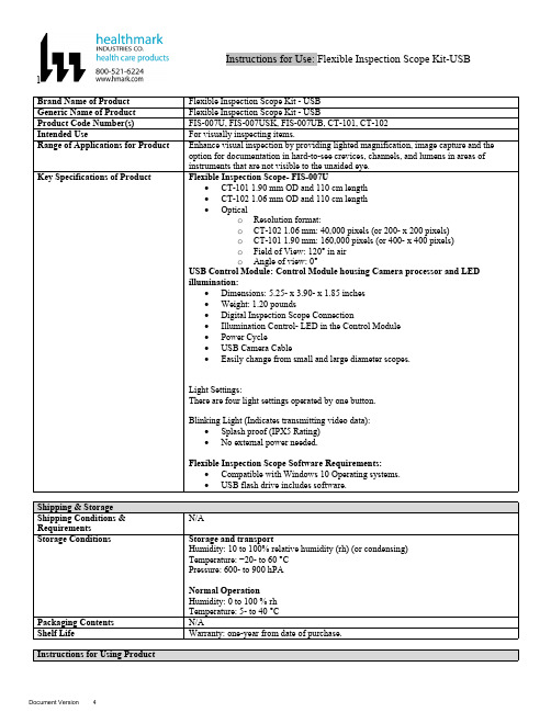
lInstructions for Use: Flexible Inspection Scope Kit-USB Brand Name of ProductFlexible Inspection Scope Kit - USB Generic Name of ProductFlexible Inspection Scope Kit - USB Product Code Number(s)FIS-007U, FIS-007USK, FIS-007UB, CT-101, CT-102Intended UseFor visually inspecting items.Range of Applications for ProductEnhance visual inspection by providing lighted magnification, image capture and the option for documentation in hard-to-see crevices, channels, and lumens in areas of instruments that are not visible to the unaided eye.Key Specifications of Product Flexible Inspection Scope- FIS-007U∙CT-101 1.90 mm OD and 110 cm length∙CT-102 1.06 mm OD and 110 cm length∙Opticalo Resolution format:o CT-102 1.06 mm: 40,000 pixels (or 200- x 200 pixels)o CT-101 1.90 mm: 160,000 pixels (or 400- x 400 pixels)o Field of View: 120° in airo Angle of view: 0°USB Control Module: Control Module housing Camera processor and LEDillumination:∙Dimensions: 5.25- x 3.90- x 1.85 inches∙Weight: 1.20 pounds ∙Digital Inspection Scope Connection∙Illumination Control- LED in the Control Module∙Power Cycle∙USB Camera Cable∙Easily change from small and large diameter scopes.Light Settings:There are four light settings operated by one button.Blinking Light (Indicates transmitting video data):∙Splash proof (IPX5 Rating)∙No external power needed.Flexible Inspection Scope Software Requirements:∙Compatible with Windows 10 Operating systems.∙USB flash drive includes software.Unpacking Flexible Inspection Scope:Carefully inspect for shipping damage. If there is any damage contact the shipping carrier and Heatlhmarkcustomer service 800-521-6224 immediately.USB Control Module: (Fig. 1).1.Digital Inspection Scope Connection 2.Illumination Control 3.Power Cycle B (Type C) on the right side of the boxFigure 1Flexible Inspection Scope™: (Fig. 2).∙CT-101 1.90 mm O.D. and 110 cm length ∙CT-102 1.06 mm O.D. and 110 cm lengthLarge1.90 mmSmall 1.06 mmFigure 2Flexible Inspection Scope™ Features3214Light/Illumination Settings: (Fig. 3).∙Five (5) light settingso Light on control indicats setting levelo Fifth setting is OFF∙Press light button to advance to next setting.∙Fifth setting turns the light OFF.Figure 3Power Cycle ButtonPress button to RESET camera (Fig. 4).Figure 41.Flexible Inspection Scope™ Plug (Fig. 5).Contains camera video connection as well as LED Light for illumination.1Figure 52.Flexible Working Length (Fig. 6).The portion of the Flexible Inspection Scope™ that is inserted into an item during visual inspection.The measuring scale markings on the Flexible Working Length are in centimeters (accuracy = ± 0.5 cm)2Figure 63.Distal Camera (Fig. 7).Distal portion of Flexible Inspection Scope™ that contains the camera lens3Figure 7SOFTWARE INSTALLATION:Note: This section is done only once when connecting the scope to the computer for the first time.∙System Requirements: MS Windows 10∙Install the Flexible Inspection Scope™ Software from the USB flash drive on a computer.Note: If you have any IT policies that may block this installation, please contact your IT team to give access to Healthmark scope viewer to install.1. Insert the USB Flash drive into your computer, and double click on the Healthmark Scope Viewer installer package to begin installation.2. The “Welcome to the Healthmark Scope Viewer Setup Wizard” screen pops up. Click on Next.3. Select the first tab Typical or setup type of your choice, click Next.4. Click Install and wait for installation to complete.5. Click Finish.STARTING SOFTWARE & CONNECTING SCOPE TO PC:(Fig 8).1.Open the Windows PC viewer software.2.Connect the Control Module to PC using USB Cable.3.Plug the Flexible Inspection Scope into the Control Module.4.In the viewer software, click Settings and Select USB Video Device, click on the desiredresolution, select the preferred Video Output Format, and then Click OK.5.Press the Power Cycle Button.Figure 86.Now you can start using the scope.Verifing OperationFollowing the steps listed below will ensure the proper use and performance of the Flexible Inspection Scope™. The Flexile Inspection Scope™ can be checked for normal operation by connecting it as described in the Startup section of this IFU.Normal operation includes:∙An image appearing on your computer monitor or HDMI Monitor.∙ A blinking light on Control Module near the Power Cycle button that indicates the image feed is transmitting.∙White light emitting from the distal end of the Digital Inspection Scope.∙An LED light on the control module top panel that indicates the light intensity of the device. Using SoftwareHealthmark Scope Viewer Software (Fig. 9).1.Capture button: Captures a Reference Image and saves it to the Reference Image folder.2.Main Image Window: Displays the image from the camera.3.Reference Image Window: Displays a reference image.4.Clear Button: Removes the image from the Reference image window.5.Open Reference Image button: Allows selection of a reference image from the Reference Imagefolder.6.Settings Button: Click to select the video camera and resolution settings.7.File Location Button: Click to change location where captured images are being saved.8.File Location Window: Shows the file path where captured images are being saved currently.9.Capture Image Button: Captures images and adds them to the File Location selected by the user(as shown in the File Location Window).10.Capture Video button: Click to record video. Click again to stop recording video.11.File Prefix: Type in text that you would like included in the file name of Captured Images.Figure 9Selecting Video Device or CameraFollow the directions below to select the video device or camera used to capture images using the Flexible Inspection Scope™ Viewer Software. (Fig. 10).1.Click Settings button in the lower left of the Scope Viewer software to display a list of videodevices or cameras being detected by your computer2.Select a device for capturing images using the Scope Viewera.The example below shows a webcam and USB Video Device in the Settings box. Select theUSB Video Device for the Flexible Inspection Scope™.b.You can also select your preferred Video Output Format from the dropdown box3.Click OK to view the selected Video Device.231Figure 10Capturing Still PicturesFollow the instructions for capturing still pictures from the Main Image Window.Select the Capture Image button. (Fig. 11).Figure 11Note: When an image is captured, “Image Captured” in red text will flash on the lower portion of the screen and a new file will appear in the Files Location.Capturing Video ImagesFollow the instructions below for capturing video from the Main Image Window.1.Select the Capture Video Button (Fig. 12).Figure 122.When the video is recording “Recording…” in red text will appear toward the bottom of thesoftware window.3.To stop recording, click Stop Capture. (Fig. 13).Figure 13Setting File PrefixFollowing the steps below allows you to create a file prefix that will appear after the underscore of image file names save to the File Location specified by the user.1.Click in the field next to File Prefix.2.Enter the characters that you would like to be included in the file name. (Fig 14).Figure 14Setting Location for Saved FilesFollowing the steps below allows you to set the file location of saved images using the Scope Viewer software.1.Click the File Location button.2.Select the file location you want to save captured images. (Fig 15).Figure 15Displaying Reference ImageThere are two ways to display a still image in the Reference Image Window on the Scope Viewer software.1.To display an image currently being displayed in the Main Image Window, click the Capture button. Note: The images will be saved in a file folder titled Reference Images in the designated File Location that the user specified in the File Location field. (Fig. 16).Figure 162.To display a saved image in the Reference Image Window from your File Location:a.Click the Open Reference Image button (Fig. 16 above).b.Select the file you want to display (Fig. 17 below).c.Click the OK Button, to display the image in the Reference Image Window. (Fig. 17).Figure 17Switching to a Different Flexible Inspection Scope™ on the Control Module:1.Press the Power button on the Control Module once.2.Disconnect the current Flexible Inspection Scope from the Control Module.3.Repeat the steps in the “STARTING SOFTWARE & CONNECTING SCOPE TO PC” procedure.Inserting Scope in ItemFigure 1Rotating Device to Avoid ObstacleFigure 2 Performing InspectionWipe down the Flexible Inspection Scope™ with a compatible wipe. Follow the manufacturer’s (Mfr.’s)Instructions for Use (IFU) for appropriate wipe usage. Click here to see the Chemical Compatibility Chart(PDF) for approved cleaning.The Flexible Inspection Scope™ is made of the same material as other common endoscopes. Any wipe,solution, or low temperature (≤ 60 °C [140 °F]) method intended for the reprocessing of endoscopes is likelycompatible with the Generation II Flexible Inspection Scope™ Catheters if used according to the productlabeling.Solutions Containing (Flexible Inspection Scope Only)Alcohol Ethoxylates Neutral or Near-Neutral pH DetergentsEnzymatic Cleaning Solutions Enzymatic DetergentsSodium Borated, Decahydrate Tetrapotassium PyrophosphateFlexible Inspection Scope™ has a fluid ingress protection rating of IPX7 (Waterproof) and can withstandimmersion in fluid up to one (1)-meter in depth for up to 30 minutes.Control Module USB has a fluid ingress protection rating of IPX5 (Water resistant) and can withstand asustained, low pressure water jet spray for up to three minutes.For Thorough Cleaning: CablesFollow the cleaning agent Mfr.’s IFU.1.Unplug and disconnect all components from the Control box prior to cleaning.2.Do not submerge or soak the cable for disinfection (cable is not waterproof).3.Wipe thoroughly with non-linting wipe moistened with facility approved neutral detergent. Use theappropriate brushes with detergent solution to remove any residues from areas that cannot bereached with the wipes.For Thorough Cleaning: Control Module1.Unplug and disconnect all components from the Control box prior to cleaning.2.Do not submerge or soak the cable for disinfection (Control Box is not waterproof).3.Wipe thoroughly with non-linting wipe moistened with facility approved neutral detergent. Use theappropriate brushes with detergent solution to remove any residues from areas that cannot bereached with the wipes.Note: Do NOT soak. Control Module and cables are not waterproof and should not be immersed.N/ACleaning –AutomatedDisinfection Control Module and CablesThese may be cleaned with alcohol based disinfectant wipes.Compatible agents (wipes and solutions) for disinfecting Flexible Inspection Scope™ and ControlModule:∙Hydrogen peroxide∙Isopropyl alcohol (IPA)∙Sodium hypochlorite (Bleach)∙Ortho-phenylphenol∙Quaternary ammonium.High-Level Disinfection (Flexible Inspection Scope™ Only)∙Select only disinfecting solutions listed in the compatible disinfecting methods.∙Follow all recommendations regarding health-hazards, dispensing, measuring, and storage from the Mfr. of cleaning and disinfecting agents.∙Soak the Flexible Inspection Scope™ in selected disinfecting solution per Mfr.’s IFU.∙Rinse the Flexible Inspection Scope™ with critical (sterile) water, again, following the disinfecting solutions Mfr.’s instructions.Reprocessing Chemical Compatibility Chart (PDF): Click here.。
GigaSPEED XL 3071E-B ETL Verified Category 6 U UTP
GigaSPEED XL® 3071E-B ETL Verified Category 6 U/UTP Cable, lowsmoke zero halogen, white jacket, 4 pair count, 1000 ft (305 m) length,reelProduct ClassificationRegional Availability EMEAPortfolio SYSTIMAX®Product Type Twisted pair cableProduct Brand GigaSPEED XL®General SpecificationsProduct Number3071EANSI/TIA Category6Cable Component Type HorizontalCable Type U/UTP (unshielded)Conductor Type, singles SolidConductors, quantity8Jacket Color WhitePairs, quantity4Separator Type BisectorTransmission Standards ANSI/TIA-568.2-D | CENELEC EN 50288-6-1 | ISO/IEC 11801 Class E DimensionsCable Length304.8 m | 1000 ftDiameter Over Insulated Conductor 1.041 mm | 0.041 inDiameter Over Jacket, nominal 5.918 mm | 0.233 inJacket Thickness0.559 mm | 0.022 inConductor Gauge, singles23 AWG13Page ofCross Section DrawingElectrical Specificationsdc Resistance Unbalance, maximum 5 %dc Resistance, maximum7.61 ohms/100 m | 2.32 ohms/100 ftDielectric Strength, minimum2500 VdcMutual Capacitance at Frequency 5.6 nF/100 m @ 1 kHzNominal Velocity of Propagation (NVP)70 %Operating Frequency, maximum300 MHzOperating Voltage, maximum80 VRemote Powering Fully complies with the recommendations set forth by IEEE 802.3bt (Type4) for the safe delivery of power over LAN cable when installed accordingto ISO/IEC 14763-2, CENELEC EN 50174-1, CENELEC EN 50174-2 or TIATSB-184-ASegregation Class cMaterial SpecificationsConductor Material Bare copperInsulation Material PolyolefinJacket Material Low Smoke Zero Halogen (LSZH)Separator Material PolyolefinPage of23Mechanical SpecificationsPulling Tension, maximum11.34 kg | 25 lbEnvironmental SpecificationsInstallation temperature0 °C to +60 °C (+32 °F to +140 °F)Operating Temperature-20 °C to +60 °C (-4 °F to +140 °F)Acid Gas Test Method EN 50267-2-3EN50575 CPR Cable EuroClass Fire Performance B2caEN50575 CPR Cable EuroClass Smoke Rating s1aEN50575 CPR Cable EuroClass Droplets Rating d0EN50575 CPR Cable EuroClass Acidity Rating a1Environmental Space Low Smoke Zero Halogen (LSZH)Smoke Test Method IEC 61034-2Packaging and WeightsCable weight38.097 kg/km | 25.6 lb/kftPackaging Type ReelRegulatory Compliance/CertificationsAgency ClassificationCENELEC EN 50575 compliant, Declaration of Performance (DoP) availableCHINA-ROHS Below maximum concentration valueISO 9001:2015Designed, manufactured and/or distributed under this quality management system REACH-SVHC Compliant as per SVHC revision on /ProductCompliance ROHSCompliantPage of33。
Endress+Hauser DeviceCare设备配置工具说明书
Configuration tool for devices via fieldbus protocols and Endress+Hauser service protocolsApplicationDeviceCare is the tool developed by Endress+Hauser for the configuration of Endress+Hauser devices. All smart devices in a plant can be configured via a point-to-point or point-to-bus connection. The status information given provides users with a simple yet effective tool for monitoring devices. Automatic functions and wizards guide the user easily through the program. The user-friendly menus enable transparent and intuitive access to the field devices.Your benefits•Fast and easy installation, online application updates, one-click connection to devices •Automatic hardware identification and driver catalog update •Device configuration with DTMs, Heartbeat verification support •Multi-language support, touch-ready for tablet use •Integrated help, wizards and event reporting •The following communication protocols are supported: HART, PROFIBUS DP/PA,FOUNDATION Fieldbus, Modbus, CDI and Endress+Hauser service interfaces •Hardware interfaces for modems (USB/RS232), Bluetooth, TCP/IP and USBProducts Solutions ServicesTechnical Information DeviceCare SFE100Configuration of Endress+Hauser devicesTI01134S/04/EN/06.1771379781DeviceCare SFE1002Endress+HauserTable of contentsDocument information .......................3Symbols for certain types of information .. (3)Function and system design (3)Function ...................................3System design ................................3Operation .................................5System integration . (5)Ordering Information (6)Additional documentation ....................6DeviceCare SFE100............................6FieldCare SFE500.............................6Plant Asset Management (6)Registered trademarks (6)DeviceCare SFE100Endress+Hauser 3Document informationFunction and system designFunction DeviceCare is a free configuration tool for Endress+Hauser devices. It supports devices with the following protocols, provided a suitable device driver (DTM) is installed: HART, PROFIBUS,FOUNDATION Fieldbus, Ethernet/IP, Modbus, CDI, ISS, IPC and PCP. The tool is aimed at customers without a digital network in plants and workshops and Endress+Hauser service technicians. The devices can be connected directly via a modem (point-to-point) or a bus system (point-to-bus).DeviceCare is fast, easy and intuitive to use. It can run on a PC, laptop or tablet with a Windows operating system.System designHART point-to-point connectionFig. 1 shows a HART point-to-point connection with an FXA195 USB/HART modem. If an FXA195 is connected to the computer, DeviceCare can connect to the device automatically.1Point-to-point connection with a HART field device 1DeviceCare 2HART FXA1953Field deviceTo establish communication with the HART device, a resistor of at least 250 Ω must be provided in the circuit. The way in which this is done depends upon the system architecture and power source used. Please read the FXA195 manual carefully.DeviceCare SFE1004Endress+HauserPROFIBUS point-to-bus connectionFig. 2 shows how the connection from PROFIBUS DP to PROFIBUS PA can be established using a Siemens DP/PA Link or a Pepperl+Fuchs SK3.2PROFIBUS point-to-bus connection 1DeviceCare 2FieldgateSFG5003PROFIBUS DP 4Segment coupler 5PROFIBUS PACDI point-to-point connectionFig. 3 shows a CDI point-to-point connection with an FXA291 modem. If an FXA291 is connected tothe computer, DeviceCare can connect to the device automatically.3CDI point-to-point connection to a device 1DeviceCare 2CDI FXA2913Field deviceDeviceCare SFE100Endress+Hauser 5Operation•Standard configurable Windows graphical user interface with icons, short cuts etc.•Hardware: Windows PC, laptop, tablet •Supported operating systems: Windows 7, 8, 8.1, 10 (32/64-bit)•Connection to Endress+Hauser devices automatic or via wizard •Choice of languages in DeviceCare: AR, CS, DE, ES, FI, FR, ID, IT, JA, KO, NL, PL, PT, RU, SA, SV, TH,TR, VI, ZH •DTM graphical user interface and language depend on the device and supplierSystem integrationSystem requirementsOperating systemThe date indicates when standard supports ends. It is possible to extend Microsoft support by another five years.HardwareSoftware required•Microsoft .Net 3.5•Microsoft .Net 4.x •PDF readerInstalled software•DeviceCare •USB driver •CommDTMs •Microsoft .Net 3.5•The DeviceDTMs for your devices must be selected and installed by the user •Endress+Hauser DTMs for SFG500 and SWA70 must be additionally installed •A PDF printer must be installed to save the device reports in PDF format •The DTM for Siemens DP/PA Link must be additionally installed •The DTM for Modbus must be additionally installedDeviceCare SFE1006Endress+HauserOrdering InformationDetailed information about the product structure is available:•In the Product Configurator on the Endress+Hauser web site: /SFE100•From the Endress+Hauser Sales Center: Additional documentationDeviceCare SFE100Innovations IN01047S/04/EN FieldCare SFE500•Getting Started KA01303S/04/EN •Operating Instructions BA00065S/04/EN •Technical Information TI00028S/04/EN •Tutorial for FieldCare projects SD01928S/04/EN •Competence Brochure CP00001S/04/ENPlant Asset Management Fields of Activity FA00024S/04/ENRegistered trademarksPROFIBUS® is a registered trademark of the PROFIBUS User Organization, Karlsruhe/Germany.FOUNDATION Fieldbus TM is the trademark of the FieldComm Group, Austin, TX 78759, USA.HART®, WirelessHART® is the registered trademark of the FieldComm Group, Austin, TX 78759,USA.Ethernet/IP is the registered trademark of ODVA, Michigan USA.Modbus is the registered trademark of Modicon, Incorporated.Microsoft®, Windows 8.1®, Windows XP®, Windows 2008 Server®, Windows 7®, Windows 10®,Internet Explorer® and the Microsoft logo are registered trademarks of the Microsoft Corporation.All other brand and product names are trademarks or registered trademarks of the companies and organizations in question.。
DS-2XS6A46G1 P-IZS C36S80 4 MP ANPR 自动 Number Plat

DS-2XS6A46G1/P-IZS/C36S804 MP ANPR Bullet Solar Power 4G Network Camera KitIt can be used in the areas that are not suitable for laying wired network and electric supply lines, or used for the scenes that feature tough environment and have high demanding for device stability. It can be used for monitoring the farms, electric power cables, water and river system, oil pipelines and key forest areas.It also can be used in the temporary monitoring scenes, such as the large-scale competitions, the sudden public activity, the temporary traffic control and the city construction.Empowered by deep learning algorithms, Hikvision AcuSense technology brings human and vehicle targets classification alarms to front- and back-end devices. The system focuses on human and vehicle targets, vastly improving alarm efficiency and effectiveness.⏹ 80 W photovoltaic panel, 360 Wh chargeable lithium battery⏹ Clear imaging against strong back light due to 120 dB trueWDR technology⏹ Focus on human and vehicle targets classification based ondeep learning⏹Support battery management, battery display, batteryhigh-low temperature protection, charge-dischargeprotection, low-battery sleep protection and remotewakeup ⏹ LTE-TDD/LTE-FDD/WCDMA/GSM 4G wireless networktransmission, support Micro SIM card⏹Water and dust resistant (IP66) *The Wi-Fi module of this product only supports AP mode on Channel 11, and does not support other modes and channels.FunctionRoad Traffic and Vehicle DetectionWith embedded deep learning based license plate capture and recognition algorithms, the camera alone can achieve plate capture and recognition. The algorithm enjoys the high recognition accuracy of common plates and complex-structured plates, which is a great step forward comparing to traditional algorithms. Blocklist and allowlist are available for plate categorization and separate alarm triggering.SpecificationCameraImage Sensor 1/1.8" Progressive Scan CMOSMax. Resolution 2560 × 1440Min. Illumination Color: 0.0005 Lux @ (F1.2, AGC ON), B/W: 0 Lux with light Shutter Time 1 s to 1/100,000 sLensLens Type Auto, Semi-auto, ManualFocal Length & FOV 2.8 to 12 mm, horizontal FOV 107.4° to 39.8°, vertical FOV 56° to 22.4°, diagonal FOV 130.1° to 45.7°8 to 32 mm, horizontal FOV 40.3° to 14.5°, vertical FOV 22.1° to 8.2°, diagonal FOV 46.9° to 16.5°Iris Type Auto-irisLens Mount All In One LensAperture 2.8 to 12 mm: F1.2, 8 to 32 mm: F1.6 DORIDORI 2.8 to 12 mm:Wide: D: 60.0 m, O: 23.8 m, R: 12.0 m, I: 6.0 m Tele: D: 149.0 m, O: 59.1 m, R: 29.8 m, I: 14.9 m 8 to 32 mm:Wide: D: 150.3 m, O: 59.7 m, R: 30.1 m, I: 15.0 m Tele: D: 400 m, O: 158.7 m, R: 80 m, I: 40 mIlluminatorSupplement Light Type IRSupplement Light Range 2.8 to 12 mm: Up to 30 m 8 to 32 mm: Up to 50 mSmart Supplement Light Yes VideoMain Stream Performance mode:50 Hz: 25 fps (2560 × 1440, 1920 × 1080, 1280 × 720) 60 Hz: 30 fps (2560 × 1440, 1920 × 1080, 1280 × 720) Proactive mode:50 Hz: 12.5 fps (2560 × 1440, 1920 × 1080, 1280 × 720) 60 Hz: 15 fps (2560 × 1440, 1920 × 1080, 1280 × 720)Sub-Stream Performance mode:50 Hz: 25 fps (640 × 480, 640 × 360) 60 Hz: 30 fps (640 × 480, 640 × 360) Proactive mode:50 Hz: 12.5 fps (640 × 480, 640 × 360) 60 Hz: 15 fps (640 × 480, 640 × 360)Third Stream 50 Hz: 1 fps (1280 × 720, 640 × 480) 60 Hz: 1 fps (1280 × 720, 640 × 480)Video Compression Main stream: H.264/H.265Sub-stream: H.264/H.265/MJPEGThird Stream: H.265/H.264*Performance mode: main stream supports H.264+, H.265+Video Bit Rate 32 Kbps to 8 MbpsH.264 Type Baseline Profile, Main Profile, High ProfileH.265 Type Main ProfileBit Rate Control CBR/VBRScalable Video Coding (SVC) H.264 and H.265 encodingRegion of Interest (ROI) 4 fixed regions for main streamAudioAudio Compression G.711/G.722.1/G.726/MP2L2/PCM/MP3/AAC-LCAudio Bit Rate 64 Kbps (G.711ulaw/G.711alaw)/16 Kbps (G.722.1)/16 Kbps (G.726)/32 to 192 Kbps (MP2L2)/8 to 320 Kbps (MP3)/16 to 64 Kbps (AAC-LC)Audio Sampling Rate 8 kHz/16 kHz/32 kHz/44.1 kHz/48 kHzEnvironment Noise Filtering YesNetworkSimultaneous Live View Up to 6 channelsAPI Open Network Video Interface (Profile S, Profile G, Profile T), ISAPI, SDK, ISUP, OTAPProtocols TCP/IP, ICMP, HTTP, HTTPS, FTP, DHCP, DNS, DDNS, RTP, RTSP, RTCP, NTP, UPnP, SMTP, SNMP, IGMP, 802.1X, QoS, IPv6, UDP, Bonjour, SSL/TLS, WebSocket, WebSocketsUser/Host Up to 32 users3 user levels: administrator, operator, and userSecurity Password protection, complicated password, HTTPS encryption, 802.1X authentication (EAP-TLS, EAP-LEAP, EAP-MD5), watermark, IP address filter, basic and digest authentication for HTTP/HTTPS, WSSE and digest authentication for Open Network Video Interface, RTP/RTSP over HTTPS, control timeout settings, TLS 1.2, TLS 1.3Network Storage NAS (NFS, SMB/CIFS), auto network replenishment (ANR)Together with high-end Hikvision memory card, memory card encryption and health detection are supported.Client Hik-Connect (proactive mode also supports), Hik-central ProfessionalWeb Browser Plug-in required live view: IE 10+Plug-in free live view: Chrome 57.0+, Firefox 52.0+ Local service: Chrome 57.0+, Firefox 52.0+Mobile CommunicationSIM Card Type MicroSIMFrequency LTE-TDD: Band38/40/41LTE-FDD: Band1/3/5/7/8/20/28 WCDMA: Band1/5/8GSM: 850/900/1800 MHzStandard LTE-TDD/LTE-FDD/WCDMA/GSM ImageWide Dynamic Range (WDR) 120 dBDay/Night Switch Day, Night, Auto, Schedule, Video Trigger Image Enhancement BLC, HLC, 3D DNR, DefogImage Parameters Switch YesImage Settings Saturation, brightness, contrast, sharpness, gain, white balance, adjustable by client software or web browserSNR ≥ 52 dBPrivacy Mask 4 programmable polygon privacy masks InterfaceAudio 1 input (line in), max. input amplitude: 3.3 Vpp, input impedance: 4.7 KΩ, interface type: non-equilibrium,1 output (line out), max. output amplitude: 3.3 Vpp, output impedance: 100 Ω, interface type: non-equilibriumAlarm 1 input, 1 output (max. 12 VDC, 1 A)On-Board Storage Built-in memory card slot, support microSD card, up to 256 GB, Built-in 8 GB eMMC storageReset Key YesEthernet Interface 1 RJ45 10 M/100 M self-adaptive Ethernet portWiegand 1 Wiegand (CardID 26bit, SHA-1 26bit, Hik 34bit, NEWG 72 bit) EventBasic Event Motion detection, video tampering alarm, exception (network disconnected, IP address conflict, illegal login, HDD error)Smart Event Line crossing detection, intrusion detection, region entrance detection, region exiting detection, unattended baggage detection, object removal detection, scene change detection, face detectionLinkage Upload to FTP/NAS/memory card, notify surveillance center, send email, trigger recording, trigger capture, trigger alarm output, audible warningDeep Learning FunctionRoad Traffic and Vehicle Detection Blocklist and allowlist: up to 10,000 records Support license plate recognition License plate recognition rate ≥95%GeneralPower 12 VDC ± 20%, 4-pin M8 waterproof connector1. Standby power consumption: 45 mW2. The average power consumption of 24 hours:3.5 W (4G transmission is excluded).3. The max. power consumption: 7 WMaterial Front cover: metal, body: metal, bracket: metalDimension 816.2 mm × 735.9 mm × 760 mm (32.1" × 28.9" × 29.9") (Max. size of the camera after it is completely assembled)Package Dimension 862 mm × 352 mm × 762 mm (33.9" × 13.9" × 30.0")Weight Approx. 31.885 kg (70.3 lb.)With Package Weight Approx. 25.650 kg (56.5 lb.)Storage Conditions -20 °C to 60 °C (-4 °F to 140 °F). Humidity 95% or less (non-condensing) Startup and OperatingConditions-20 °C to 60 °C (-4 °F to 140 °F). Humidity 95% or less (non-condensing)Language 33 languages: English, Russian, Estonian, Bulgarian, Hungarian, Greek, German, Italian, Czech, Slovak, French, Polish, Dutch, Portuguese, Spanish, Romanian, Danish, Swedish, Norwegian, Finnish, Croatian, Slovenian, Serbian, Turkish, Korean, Traditional Chinese, Thai, Vietnamese, Japanese, Latvian, Lithuanian, Portuguese (Brazil), UkrainianGeneral Function Anti-banding, heartbeat, mirror, flash log, password reset via email, pixel counter BatteryBattery Type LithiumCapacity 360 Wh (90 Wh for each battery)Max. Output Voltage 12.6 V Battery Voltage 10.8 VOperating Temperature Charging: -20 °C to 45 °C (-4 °F to 113 °F) Discharging: -20 °C to 60 °C (-4 °F to 140 °F)Cycle Lifetime Performance mode: 5 days, Proactive mode: 8 days, Standby mode: 80 days *in cloudy/rainy days (25 °C)Battery Life More than 500 cyclesBattery Weight Approx. 2.74 kg (6.0 lb.) (0.685 kg (1.5 lb.) for each battery) ApprovalEMC CE-EMC/UKCA (EN 55032:2015+A11:2020+A1:2020, EN 50130-4:2011+A1:2014); RCM (AS/NZS CISPR 32: 2015);IC (ICES-003: Issue 7)RF CE-RED/UKCA (EN 301908-1, EN 301908-2, EN 301908-13, EN 301511, EN 301489-1, EN 301489-52, EN 62133);ICASA: same as CE-RED;IC ID (RSS-132 Issue 3, RSS-133 Issue 6, RSS-139 Issue 3, RSS-130 Issue 2, RSS-102 Issue 5);MIC (Article 49-6-4 and 49-6-5 the relevant articles and MIC Notice No. 1299 of the Ordinance Regulating Radio Equipment)Safety CB (IEC 62368-1:2014+A11)CE-LVD/UKCA (EN 62368-1:2014/A11:2017) LOA (IEC/EN 60950-1)Environment CE-RoHS (2011/65/EU);WEEE (2012/19/EU);Reach (Regulation (EC) No 1907/2006)Protection Camera: IP66 (IEC 60529-2013)Wind resistance 12 level, up to 40 m/s wind speed resistance⏹Typical ApplicationHikvision products are classified into three levels according to their anti-corrosion performance. Refer to the following description to choose for your using environment.This model has NO SPECIFIC PROTECTION.Level DescriptionTop-level protection Hikvision products at this level are equipped for use in areas where professional anti-corrosion protection is a must. Typical application scenarios include coastlines, docks,chemical plants, and more.Moderate protection Hikvision products at this level are equipped for use in areas with moderate anti-corrosion demands. Typical application scenarios include coastal areas about 2kilometers (1.24 miles) away from coastlines, as well as areas affected by acid rain. No specific protection Hikvision products at this level are equipped for use in areas where no specific anti-corrosion protection is needed.⏹Available ModelDS-2XS6A46G1/P-IZS/C36S80 (2.8-12mm)DS-2XS6A46G1/P-IZS/C36S80 (8-32mm)Dimension。
一汽青岛汽车厂TDS中责任厂家代码与零件上的代码对照表

长春一汽四环汽车制品有限公司转向泵厂 LAC98 青岛黄海汽车配件有限公司 中车集团南京7425工厂 浙江万达汽车方向机有限公司 山东水星汽车部件集团股份有限公司 青岛林达实业有限公司 河北省安平县汽车消声器总厂 北京天元奥特橡塑有限公司 龙口旭鑫机械有限公司 山东济宁车轮厂 青岛海通车桥有限公司 德惠市北方汽车底盘零部件有限公司 中欧汽车电器有限公司 余姚市河姆渡镇双鸟汽配厂 万安集团有限公司 瑞立集团瑞安汽车零部件有限公司 山东龙口蓄电池总厂 青岛金盛集团有限公司 浙江省慈溪市三新汽车零部件有限公司 江阴圣世杰机械制造有限公司 富奥汽车零部件有限公司传动轴分公司 山东华龙机械有限公司 青岛宏顺兴工贸有限公司 青岛汽车散热器有限公司 一汽山东汽车改装厂 LIB74 LL102 LMC82 LI603 LIB83 LGB02 LDB19 LIB32 LIC22 LIB71 LA022 LFB96 LMC28 LM073 LM412 LI506 LIB77 LM017 LLB90 LAAD1 LIB25 LIB73 LIB88 LW219
青岛众力 哈市风华 富奥天合 青岛汽零 河南邦德 新泰锻造 四环怡东 长春玻璃 青州东方 即东汽配 四方塑配 上海三民 河北亚大 帅潮实业 青岛兴海 临朐大地 丹阳新泉 青岛东风 青汽实业 富奥江森 明水汽配 四平方向 江苏林慧 莱州金声 青岛林涛 天津轶超 德惠机械 威海威嘉 北京海拉 富奥减振 胶南一塑 临海滤清 黄山汽电 烟台内饰 上海通达 淄博电器 富奥辽泵 青传动轴 上海干巷 浙江万里 佳通轮胎 四环车轮 长科德宝 青岛方正 青岛精益 曼胡默尔 河北亿利
LID88
LID46 LID40 LID43 LW056 L010A LA208 LA223 LA219
齐鲁轮业有限公司
美工电子_Eaton ULT 1008 Listed 模块式转换开关产品说明说明书

Reliability, versatility and performanceEaton offers a comprehensive portfolio of UL T 1008 Listed transfer switch solutions to meet a wide variety of standby power applications. The molded case transfer switch line is not only reliable and simple to operate, but also available in a broad selection of product configurations. When coupled with our extensiv e custom engineering capabilities, finding the right transfer switch for your project has never been easier. Whether your needs are standard commercial or harsh industrial, the robust construction and performance of an Eaton transfer switch sets the standard for maintaining power to critical loads and optimizing system uptime.Product configurations•Open transition (time delayed, load voltage decay)•Automatic, non-automatic, manual operation • 30 to 1000 amperes • Two-, three- and four-pole • Up to 600 Vac, 50/60 Hz • Single-phase or three-phase •Cam-Lok E quick-connect terminals•Service entrance—UL 1008 Listed and 100% rated •Overcurrent protection with Power Xpert Release (PXR) thermal-magnetic or electronic trip unit•NEMA T 1, 12, 3R, 4X enclosure or open frame design•Automatic transfer controller: ATC-900, ATC-300+, ATC-100Codes and standards• UL 1008 Listed• CSA T C22.2 No. 178 Certified •Seismic qualified—OSHPD, CBC, IBC, UBC Zone 4•NFPA T 110 and National Electrical Code T (NEC T ) Articles 700, 701, 702, 708Features and benefits•Power Defense™ (PD) molded case switch/circuit breaker pair with self-protecting main contacts•Ability to field replace molded case switch/circuit breaker individually •Mechanically interlocked to prevent simultaneous connection of both sources •Quick-connect, multi-tap transformer panel derives control power from either source and permits field selection of system voltage • Front accessible • Top/bottom cable entry • Internal dead-front cover •Industry standard serial communication (Modbus T RTU)•Auxiliary contacts indicate position of main contacts •Dual automatic plant exercisers for scheduling unloaded and loaded engine-generator testing •Programmable control inputs and relay outputs for load management •Advanced source sensing incorporates negativesequence voltage detection for identifying phase loss condition•USB port for downloading power quality data, managing setpoint profiles and updating firmwareOptions and accessories•ATC-900 controller accessory modules:•DCT—integral powermetering (load) and 24 Vdc external supply power •I/O—expand programmable control inputs (up to 20) and Form C relay outputs (up to 20)•Advanced power quality metering (PXM series) of source or load•Surge protection device (UL 1449 5th edition)•7-inch color touch screen HMI remote annunciator to monitor and control single or multiple (up to eight) transfer switches •Ethernet communication (Modbus TCP/IP , BACnet, EtherNet/IP)•Thermostat controlled heater element for outdoor applications • Compression lug terminals •Non-automatic operatorcontrols and indication lightsService entrance rated transfer switch with Cam-Lok terminalsEaton is a registered trademark.All other trademarks are property of their respective owners.Eaton1000 Eaton Boulevard Cleveland, OH 44122United States © 2023 EatonAll Rights Reserved Printed in USAPublication No. PA140016EN / Z28189November 2023Product selectionCatalog numbering systemA Limited to 600 A and below.A Ethernet communication option requires use of serial port.Quick-connect Cam-Lok terminationTransfer switches can be configured with a Cam-Lok power panel for quick connection to a temporary emergency power source (engine-generator).The color-coded power panel resides in an isolated compartment and is constructed of industry-standard 16 series Cam-Lok receptacles (male) mounted on a high-strength fiberglass-reinforced polyester material. Each Cam-Lok receptacle is rated for 400 A and can be equipped with an optional hinged cover. Ground ampacity can be specified as 25%, 50% or 100% of the transfer switch ampere rating.Cam-Lok quick-connect panel (1000 A) with 25% (minimum) ground ampacity Cam-Lok quick-connect panelHinged bottom flapSafety interlockFollow us on social media to get the latest product and support information.。
Lorex MPX HDSe

3.
2. Clic Droit: • En mode visionnement en direct :
Contrôle des caméras PTZ (non incluses) Ajuste les réglages de la couleur et de l’image de la caméra Voir les informations du système Démarrer/arrêter le mode séquence Esactiver l’alarme sonore
6: EN MARCHE
Bip
Si le système émet un signal sonore au démarrage, le câble Ethernet n’est peut-être pas branché, ou le système n’est peut-être pas connecté à Internet. Pour arrêter le signal sonore : 1. Brancher un câble Ethernet du système au routeur et redémarrer le système. OU 2. Cliquer avec le bouton droit et cliquer sur Disable Beep.
Cliquer sur et sélectionner SETTING
4. Cliquer sur GENERAL et sélectionner l’onglet Date&Time.