PS3670 EL-2A、2Y、2AS 条形连接器_杭州老板_-产品规格书
欧洲各国2PIN电子元件插脚尺寸
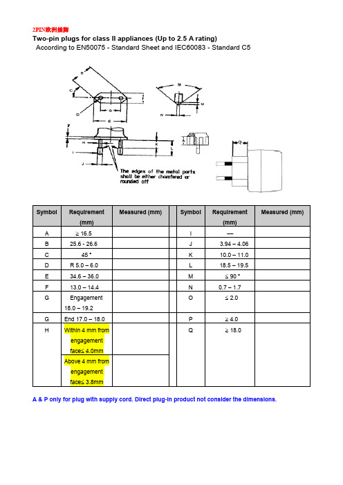
2PIN欧洲插脚Two-pin plugs for class II appliances (Up to 2.5 A rating)According to EN50075 - Standard Sheet and IEC60083 - Standard C5A & P only for plug with supply cord. Direct plug-in product not consider the dimensions.UK Plug Checking Form according to Figure 4 of BS1363-3Grounding pinPosition Required (mm) By Measurement (mm)By the gauges in Figure A1A 6.35±0.15 -B 6.35±0.15C +0.150.051.63-- D 7.92 -- P E 10.31 -- P F 17.06±0.4 - G 19.94±0.8 1 21.9 max. or 27.0 min. - 2 21.9 max. or 27.0 min. - 3 21.9 max. or 27.0 min. - 4 21.9 max. or 27.0 min.- 5 60︒ -- P 6 60︒ -- P 7 8.6 min. - 8 21.0 max. 9 20.0±1.0 10 1.0 max 118.7±0.5Position Required (mm) By Measurement (mm) By the gauges in Figure A1 Plug type (h)R 0.35±0.05 -S 0.9±0.1 -T ≥0.60-V 6 -- PDimension Checking for Two-pin plugs of NA (15 A, 125 V) According to (NEMA WD 6-2002 Figure 1-15)Dimension Checking for Tow-pin plugs (6 A, 10 A rating) According to Fig 1 of GB 1002-2008dDimension Checking for Korea plugs (Two-pole plug for 3A250V) According to KSC 8305日本插脚巴西插脚Equipment’s combined with two-pole plug (Class II) 10 A/250V a.c. (figure 13. NBR 14136: 2002)Note:1 The sketches are not intended to govern design, except as regards the dimensions shown2 Plugs can be rewirable or non-rewirableRequirements:①– The distance between the engagement face and the cord or cord guard, if any, shall be at least 14 mm②– Within this distance, the outline shall be not smaller than the engagement face.③– Within this distance, the outline shall be not larger than the engagement face.④– Insulating sleeves on the current-carrying pins are optional If the insulating sleeves are separate parts, they shall enter the plug by at least 3mm measured from the engagement face.⑤– The external diameter of the insulating sleeves shall not be larger than the diameter of the uninsulated part of the pins.⑥– To avoid damage to shutters, the ends of the pins shall show neither sharp edges nor burrs. They shall印度插脚:Indian Plug Checking WorksheetDimension: mmNote:1. “G” is the minimum distance between the pins and the periphery of the plug.IRAM 2063 Plug (Class II, two-pole) Checking Worksheet(IRAM 2063:1982 + Amd 1999)SASO Plug Checking Form according to Figure 1 of SASO 2203。
Artisan Technology Group设备维修与售卖手册说明书

Serie PSS SB 3006-3Units with two SafetyBUS p InterfacesAll rights to this documentation are reserved by Pilz GmbH & Co. KG. Copies may be made for internal purposes.Suggestions and comments for improving this documentation will be gratefully received.The names of products, goods and technologies used in this documentation are registered trademarks of the respective companies. Automation Workbench®, Pilz®, PIT®, PMI®, PNOZ®, Primo®, PSS®, SafetyBUS p® are registered trademarks of Pilz GmbH & Co. KG.ContentsContentsIntroductionThis operating manual explains the function and operation of theprogrammable safety system, describes the installation and providesguidelines on how to connect the inputs and test pulse outputs onprogrammable safety systems from the PSS SB 3006-3 series. A PSSfrom the PSS SB 3006-3 series is a 3rd generation programmable safetysystem.For connection to SafetyBUS p, units are available with one SafetyBUS pinterface as well as two SafetyBUS p interfaces.This operating manual describes the programmable safety systems fromthe PSS SB 3006-3 series with two SafetyBUS p interfaces.Different interfaces are available for connection to various non-safety-related standard bus systems, depending on the unit type. Theseinterfaces are described in separate operating manuals. The necessaryoperating manuals are supplied with the relevant unit types.Please refer to the PSS-range manuals, in particular the information andrequirements stated in the “PSS-Range Safety Manual”, “FS SystemDescription”, “ST System Description” and also the “SafetyBUS pInstallation Manual” from the SafetyBUS p manual package.Y ou will need to be conversant with the information in these manuals inorder to fully understand this manual.This documentation is intended for instruction and should be retained forfuture reference.IntroductionValidity of documentationThis documentation is valid for the following programmable safety systemsfrom the PSS SB2 3006-3 series:•PSS SB2 3006-3 DP-S from Version 1.0•PSS SB2 3006-3 IBS-S from Version 1.0•PSS SB2 3006-3 CN-A from Version 1.0•PSS SB2 3006-3 DN-S from Version 1.0•PSS SB2 3006-3 ETH-2 from Version 1.0•PSS SB2 3006-3 ETH-2 DP-S from Version 1.0•PSS SB2 3006-3 ETH-2 IBS-S from Version 1.0It is valid until new documentation is published. The latest documentationis always enclosed with the unit.Overview of documentation1IntroductionThe introduction is designed to familiarise you with the contents,structure and specific order of this manual.2OverviewThis chapter provides information on the most important features ofthe programmable safety systems.3SafetyThis chapter must be read as it contains important information onsafety regulations and intended use.4Function DescriptionThis chapter describes the individual components of theprogrammable safety systems: CPU, inputs and test pulse outputs.5InstallationThis chapter explains how to install the programmable safetysystems.6Supply VoltageThis chapter explains what you need to consider when connecting thesupply voltage.7Wiring the Inputs and Test Pulse OutputsThis chapter describes the safety-related wiring of the inputs and testpulse outputs.8InterfacesThis chapter describes the configuration of the available interfaces.9Operation and MaintenanceThis chapter explains how to commission the safety systems andadvises on what to do if a fault occurs.10Technical Details11AppendixIntroductionOverviewOverviewAUTO PGSTFSPSS SB2 3006-3 DP-S4F-StackOverviewAUTO PGSTFSPSS SB2 3006-3 IBS-S4F-StackOverviewAUTO PGSTFSPSS SB2 3006-3 CN-A 4F-StackOverviewAUTO PGSTFSPSS SB2 3006-3 DN-S 4F-StackOverviewAUTO PGSTFSPSS SB2 3006-3 ETH-24F-StackOverviewAUTO PGSTFSPSS SB2 3006-3 ETH-2 DP-S 4F-StackOverviewAUTO PGSTFSPSS SB2 3006-3 ETH-2 IBS-S 4F-StackPG 6OverviewSafetySafetyDigital inputs (DI2)Depending on the application area and its respective regulations, the PSSmay be used without test pulses for applications up to category 3in accordance with EN 954-1 (03/97). The possibility of a short circuitoccurring in the external wiring between different inputs or to L+ must beeliminated through appropriate wiring.T est pulses must be used for category 4 applications (for connectionexamples please see Chapter 7, “Wiring the Inputs and T est PulseOutputs”).Safety guidelinesFailure to keep to these guidelines will render all warranty and liabilityclaims invalid:•All health and safety / accident prevention regulations for the particulararea of application must be observed.•Before using the unit it is necessary to perform a safety assessment inaccordance with the Machinery Directive 98/37/EC.Use of qualified personnelThe safety system may only be assembled, installed, programmed,commissioned, operated, maintained and decomissioned by qualifiedpersonnel. Qualified personnel are people who, because they are:•Qualified electrical engineers and• Have received training from qualified electrical engineers,are suitably experienced to operate devices, systems, plant and machineryin accordance with the general standards and guidelines for safetytechnology.SafetyEMCDThe safety system is designed for use in an industrial environment.Interference may occur if used within a domestic environment. Warranty and liabilityAll claims to warranty and liability will be rendered invalid if:•The safety system was used contrary to the purpose for which it wasintended•Damage can be attributed to not having followed the guidelines in themanual•Operating personnel are not suitably qualified.•Any type of modification has been made (e.g. exchanging componentson the PCB boards, soldering work etc.).DisposalThe programmable safety system must be disposed of properly when itreaches the end of its service life.Function DescriptionCPUThe CPU controls the test pulse outputs, reads the inputs and processes /stores the user program and variable data. The failsafe section is designedto be multi-channel, i.e. different CPUs process the user programindependently.A four-digit display and several LEDs provide information on the status ofthe safety system and indicate any errors.Function DescriptionInterfacesCPU interfacesThe CPU of each programmable safety system in the PSS SB2 3006-3series provides the following interfaces:•Programming device interfaceCombined RS 232 interface (minimum configuration: TxD, RxD, GND)/RS 485•User interfaceCombined RS 232/RS 485 interfaceFor further information please refer to the “System Manual for thePSS-Range”.SafetyBUS p interfaceEach programmable safety system in the PSS SB2 3006-3 series has twoSafetyBUS p interfaces.The second SafetyBUS p interface can be used to divide up large plants.This can help to optimise the reaction time.For further information on SafetyBUS p, please refer to the “SystemManual for SafetyBUS p”.Interfaces for standard bus systemsDifferent interfaces are available for connection to various standard bussystems, depending on the unit type. The standard bus interfaces aredescribed in separate operating manuals. The necessary operatingmanuals are supplied with the relevant unit types.Digital inputs (DI2)All programmable safety systems in the PSS SB2 3006-3 series have sixintegral on-board inputs, which are suitable for connecting single and dual-channel input devices, with or without test pulses. Input signals must showa “High” (“1” signal) of 24 VDC (+15 ... +30 VDC) and a “Low” (“0” signal)of 0 VDC (-3 ... +5 VDC).LEDs are used as status indicators. An LED lights up as soon as a “1”signal is present at the input. All inputs have input filters.Internal diagnostic circuitry checks the function of the inputs, including theinput filter. If an error occurs, the PSS will switch to a STOP condition andoutput a message to the CPU display. In addition, all the decentralisedoutputs in the I/O-Groups assigned to the PSS Logic Device will beswitched off (see also “SafetyBUS p System Description”).Where test pulses are not used, inputs with single-channel input devicescan be used in applications up to and including Category 2 in accordancewith EN 954-1; in the case of dual-channel input devices, this extends toCategory 3 applications. The device should be suitably wired to eliminatethe risk of a short circuit in the external wiring between the different inputsand also between the PSS supply and any bus interface.Test pulses must be used for applications with single-channel inputdevices above Category 2 and for applications with dual-channel inputdevices above Category 3. Connection examples can be found in Chapter 7of this manual, “Wiring the Inputs and Test Pulse Outputs”.Function DescriptionInstallationInstallationAUTO PG STFS PSS SB 3006-3 DP-S F-StackST FSST FSInstallationSupply VoltageSupply VoltageSupply VoltageSupply VoltageNotes on wiring•Minimum range for cable cross sections on field connection terminals inmm2, in accordance with EN 61131-2, 07/00:-Power supply: 1.5 (AWG16) ... 2.5 (AWG12)-Functional earth: 1.5 (AWG16) ... 2.5 (AWG12)•Use copper wiring.•The torque setting on the terminals should be 0.5 … 0.6 Nm.Wiring the Inputs and Test Pulse Outputs AUTO PG ST FS PSS SB2 3006-3 IBS-S F-StackWiring the Inputs and Test Pulse Outputs•Connecting and laying the cables-Screened cables are not required for digital I/Os. However, if theconnection cables have screening, it should be connected at one end. -Minimum range for cable cross sections on field connection terminals in mm2, in accordance with EN 61131-2, 07/00:¤Digital inputs:0.5 (AWG20) ... 1.5 (AWG16)¤Test pulse outputs:0.5 (AWG20) ... 1.5 (AWG16)¤Power supply: 1.5 (AWG16) ... 2.5 (AWG12)¤Functional earth: 1.5 (AWG16) ... 2.5 (AWG12)-If you use a multi-strand cable with a cross section of 1.5 mm2 toconnect the inputs and test pulse outputs, you will need to use ferrules conforming to DIN 46228, Part 1 and Part 2 0.5 ... 1.5 mm2, Form A orC. To crimp the ferrules you can use crimp pliers (crimp form A or C)conforming to EN 60947-1, such as the PZ 1.5 or PZ 6.5 fromWeidmüller, for example.-Use copper wiring.-The torque setting on the terminals should be 0.5 … 0.6 Nm.The terms “signal inputs with frequent operation” and “single-channel safe input devices” are used in the wiring examples. These terms are defined as follows:•Signal inputs with frequent operationThese are signals which change status on several occasions within a period of time.•Single-channel safe input devicesThese are positively-driven, normally-closed contacts which open on actuation (failsafe principle).Wiring the Inputs and Test Pulse Outputs。
ARTISAN TECHNOLOGY GROUP 设备购买和维修服务说明

MPT SERIESFax (406) 587-4911INTERNAL JUMPER SELECTIONSensor Type: Factory default is for operation with Thermistors, RTD, or LM335. If you are using an AD590, move the jumper from “ALL OTHERS” to “AD590”. An AD590 must be biased by at least +8V. If V+ exceeds +8V, it can be used for bias. Use pin 10 for the other AD590 connection, and do not connect pin 9. (See the Quick Connection diagram on page 3.)Sensor Current: The resistance of the sensor you choose, in conjunction with the sensor current, must produce a voltage between 0 V and 5 V in order to be used in the control loop. The 10 µA and 100 µA sensor currents are used with thermistors. The 1 mA sensor current is used with the LM335 IC Sensor and 500 or 1000Ω RTDs. The 10mA bias current (available on Rev. E) is for 100Ω RTDs.The voltage produced by your sensor is given by: V = R SENSOR * I SENSORCurrent Limit: Factory default is 0 A for the Current Limit Trimpot. Rotate this Trimpot clockwise to the desired maximum output current. The following charts detail the current limit settings available for each unit. PRODUCT REVISION CURRENT LIMIT TRIMPOT POSITIONSRev. G (Introduced 10/2014.)Tick Marks012345678 MPT25000A0.312A0.625A0.937A 1.25A 1.56A 1.87A 2.19A 2.5A MPT50000A0.4A1A 1.6A 2.2A 2.8A 3.75A 4.3A5A MPT100000A1A 2.5A 3.75A5A 6.25A7.75A8.75A10ARev. E (Introduced 9/2003.) &Rev. F(introduced 3/2005.)012345678910 MPT25000A250mA500mA750mA1A 1.25A 1.5A 1.75A2A 2.25A 2.5A MPT50000A500mA1A 1.5A2A 2.5A3A 3.5A4A 4.5A5A MPT100000A1A2A3A4A5A6A7A8A9A10ARev. D(Each setting represents a 20% increment of full scale current.)12345 MPT25000.5A1A 1.5A2A 2.5A MPT50001A2A3A4A5A MPT100002A4A6A8A10AProportional Gain: Measure resistance across the two test points labeled above to determine the gain setting. Factory default is a gain of 25.For MPT2500, Resistance = Gain * 4000; Default 100kΩFor MPT5000, Resistance = Gain * 2000; Default 51kΩFor MPT10000, Resistance = Gain * 1000; Default 25kΩMPT2500-00400-K © 2014 Wavelength Electronics, Inc. 6MPT2500-00400-K © 2014 Wavelength Electronics, Inc. 7A BCBBFIGURE AFIGURE B* All Other Tolerances are +/-5%MPT SERIES SELECTION GUIDE FIGMPT-2500 2.5 A Temperature Controller A MPT-5000 5 A Temperature Controller A MPT-1000010 A Temperature Controller B OPTIONAL ACCESSORIES AVAILABLE FOR SYSTEMDEVELOPMENT:CKT-202A connector kit includes the appropriate 15 pin D-sub connector, hood and hardware.WCB-101A Cable Kit includes one meter of cable soldered to a mating connector on one end and unterminated on the other.Precision thermistors for various temperature ranges areoffered with detailed R-T charts for quick system integration.MODEL R @ 25°C10 µA RANGE100 µA RANGETCS-605 5 k Ω- 55°C to - 2°C -20°C to +33°C TCS-61010 k Ω- 45°C to +13°C -8°C to +50°C TCS-10K510 k Ω- 45°C to +13°C -8°C to +50°C TCS-62020 k Ω- 35°C to +28°C +6°C to +69°C TCS-65050 k Ω- 18°C to +49°C +25°C to +92°CTCS-651100 k Ω- 6°Cto+67°C+41°Cto+114°CMPT2500-00400-K © 2014 Wavelength Electronics, Inc. 10Connector Kit CKT-202Cable KitWCB-101CAT-203 MPT I/O CABLECABL E #1CABL E #2RED/BLACK 2GREEN WHITE/BLACK WHITE BLUE WHITEBLACK BLUE ORANGE REDGREEN/BLACK ORANGE 1115131412109784563BLACK RED WIRE COLOR PIN 1GREEN 1111211211222CABLE #21Modulation Input Modulation GND (for pin 6)Temp Setpoint Monitor V+Temp MonitorMonitor GND (for 11 & 12)GND (For pins 7 & 8)V+Sensor +Sensor - (GND)TEC+TEC+TEC-TEC-FUNCTIONGND (For pins 7 & 8)WCB-101 MPT I/O CABLEArtisan Technology Group - Quality Instrumentation ... Guaranteed | (888) 88-SOURCE | 。
★常用接插件型号(图文)-自己总结

常用接插件型号(图文)2.54间距的叫SCN2.0间距的叫SAN端子187端子护套2个4.2间距公壳型号5557 母壳PH2.0XH-8PFD-14P 2.54间距CH3.96VH3.96ZH(1.5间距)EL特指4.5间距,SM指2.54间距DG1000-2P接插件LED显示屏/LED显示屏散件/P10半户外/16P排线压头FC-16P接插件接插件2.54间距2*40P 双排针双排直针5.08-301-2P 接插件针座端子接插件SM 脚距2.54 线1007 公端子接插件2.8插簧插片2.8MM 铜XH-2.54-2P接插件1+1接插件VH3.96-2P接插件DC3-10P接插件接插件间距4.5MM 对插接插件接插件焊接式公头DB25接插件EL 2P 条形连接器接插件CH3.96-5P接插件RS232串口DB9母头DB9孔全铜接插件标准6.3MM 插簧插片护套0.5元/套冷压接线端子5.0MM 两位接插件2.54单排针,1*40P 排针接插件2.54MM接插件焊接式公头DB37 蓝色PH2.0mm胶壳、针座、端子连接器、接插件系列XH2.54-3P接插件插件座间距2.54MMfc-16P接插件KF/DG1000-2p 接插件/接插座/接线端子脚间距10MM 接插件杜邦线20CM1P-1P2P接插件(脚间距5.08mm)DC3-10P 接插件下载座JST对插接插件母壳2P(10个MOG接插件l连接器2.0MM PH-2A针座(插座2.8端子型车用连接器接插件线缆连接器连接件对接2线串口头接插件DR9针式板载式焊接式弯针插座(母头) RS232杜邦(间距2.0mm)双排胶壳,针座,端子连接器、接插件系列接插件KF2510-6P 间距2.54接插件一套包括:头子+座子+簧片适配器适配座转换座PLCC44转DIP40 PLCC-44芯(贴片)接插件航空插头连接器GX16-2T(2芯)接插件接插件测试插头插座十字插香蕉插0.9元一对红色4.8接插件铜件两只脚焊板插片公端子接插件6.3插簧插片6.3MM 铜HT3.96-10P橙色,接插件DB25 公头/针二排25芯接插头接插件FC-8P 排线头接插件2.54间距一套6.3插簧接插件铜件接插件白色插座2510-3芯直脚KF2510端子接插件端子2.54MM冷压头簧片5557 连接件接插件8孔连线器插座塑料连接件对插件DC3-20P接插件6.3-4 (6.3端子)型车用连接器接插件接线器4线连接件XH2.54-2P接插件间距2.54MM 一套接插件XH2.54-10P 座子+线线长20CM接插件KF-4P 拔插式接线端子KF2EDG 间距5.08MM 一套弯针SM-2P 对插锁紧接插件一套公壳+母壳+公簧片+母簧片USB A母连接头A母插座USB接插件XH2.54-5P接插件,连接器,针距2.54MM 端子座+插头+簧片一套PLCC 32贴片插座接插件连接器4.8直插/插簧/插片/对插件/单线连接器/单线接插件航空插头/GX16-2芯/一套/ 电缆连接器接插件【不锈钢】16型高品质航插航空插头航空插座接插件电连接器8芯防水对接端子防水对插连接器汽车防水接插件密封防水对插端子1套大号皮套鳄鱼夹电子接插件接线夹连线夹香蕉插座香蕉插头香蕉接头接插件测试接头B101连接器2.8端子型/车用连接器/接插件/空中对接/摩托车6PBNC插座铜镀金针BNC反接头Q9头反接焊接方式摄像机视频接插件6.3多孔接插件电子连接件车用电器连接插头插座3孔4+1接插件双皇冠接插件-MINI USB座贴片迷你MINI-5P 铁LED显示屏/LED显示屏散件/P10半户外/16P排线压头FC-16P接插件接插件杜邦线20CM8P-8P香蕉插头质量好连接头测试头接插件DIY电子实验制作配件连接器接插件SCSI68PIN双母头连接线接插件6.3带护套接插件铜件连接器TJC3 2.54 XH-2AW(2位弯脚插座/90度)批发P48-26芯大电流航空插头接头电缆接插件SM2.5-3P公母对接胶壳,端子,条形连接器,接插件,黑色,1套弯针XH2.54-2P接插件间距2.54MM 一套:插头+弯插座+端子20MOG 电源插头接插件电源座。
ARTISAN技术集团设备说明说明书

Specifications The Adept Cobra TM s800 robot is a high-performance SCARA robotThe Adept Cobra s800 robot comes with the high-performanceAdept SmartControllerthe Adept SmartServo architecture. It has a small footprint of329w x 187d x 86h mm.The Adept Cobra s800 system includes the following:• Adept Cobra s800 robot with AIB (Amplifiers In Base)• Adept SmartController motion controller • Front panel with E-Stop • Adept ACE software • User documentationOptions and Peripherals:•AdeptSight TM vision guidance and inspection system(requires a PC–Adept recommends using the Adept SmartVision TM EX)• T2 manual control pendant • Dual robot configuration option • Conveyor-tracking option • sMI6 SmartMotion TM interface• sDIO I/O expansion (32 digital input and 32 digital outputchannels)• IO Blox I/O module (8 digital input and output channels each) • High-resolution Joint 4 option • Solenoid valve kit• IP-65 + Cleanroom ISO4 (class 10) option • Adjustable Hardstop KitAdept Technology, Inc. 5960 Inglewood Drive, Pleasanton, CA 94588Tel:925-245-3400Fax:925-960-0452Email:**************Specifications subject to change without notice.©2013 Adept Technology, Inc. ALL RIGHTS RESERVED. The information provided in this communication or document is the property of Adept Technology, Inc. and is protected by copyright and other intellectual property laws. In addition, any references to any Adept Technology, Inc. products are the marks and property of Adept Technology, Inc. [and may be registered trademarks]. All other trademarks or tradenames are the property of their respective holders.09366-010 Rev. D800Dimensions Adept Cobra s800Ø 41.15Ø 63Grounding M3 x 0.5 - 6HØ 6Dimensions: Flange (mm)Dimensions: Footprint (mm)Downloads:Download CAD files for the Adept Cobra s800 robot from /support/downloads/file-search using the following download ID: 500008Work Envelope: Radius 800 mm Inner Limit: Radius 164 mm Height: 210 mmRequired clearance to open AIB Chassis918894184210+/- 360°183+/- 360°160160200338。
设备使用说明书

立式收口机使用说明书镇江市恒源汽车零部件有限公司非常感谢您选择使用镇江市恒源汽车零部件有限公司生产的立式收口机,请详细阅读本品的使用说明书,以便于您的安全使用。
目录1.安全说明................................................................................................... 错误!未定义书签。
2.设备用途和适用范围................................................................................. 错误!未定义书签。
3.设备参数................................................................................................... 错误!未定义书签。
4.设备动力系统............................................................................................ 错误!未定义书签。
5.设备操纵系统............................................................................................ 错误!未定义书签。
6.设备电气系统............................................................................................ 错误!未定义书签。
7.设备冷却系统............................................................................................ 错误!未定义书签。
电梯配件价格(迅达)

序号提供厂家商品名称规格单位单价1迅达防偏轮9300扶手带防偏轮个15.33 2迅达玻璃板9300下圆弧段玻璃板块251.76 3迅达转向链E型扶手滚轮链 N=900 (EN)(转向链)条229.71 4迅达主板MF4 主付印板块6,078.88 5迅达夹头R型夹头个 3.23 6迅达单相断路器SIS2单相断路器C4(H23自动空气开关)C4A/1P个17.47 7迅达涨紧套SWE涨紧套个215.47 8迅达方向灯ф60方向灯个1,089.85 9迅达变压器变压器仅用于MF 380V/415V个568.35 10迅达弹性体弹性体SDS SWE N-EUPEX B95 PERBUNAN个1,193.72 11迅达导向滚轮导向滚轮个34.71 12迅达导向件导向件个 6.11 13迅达导向链导向链 (F5)个301.47 14迅达电磁铁电磁铁 F.9300/9500/9700个1,570.84 15迅达电源电源NGF24.Q个265.59 16迅达端头玻璃端头玻璃9300-00-EN-M(无色)块244.64 17迅达端头玻璃端头玻璃9300-00-ET-M(无色)块279.14 18迅达多楔带多楔带条1,692.07 19迅达多楔带滚轮多楔带滚轮Z556225 9300个67.72 20迅达法兰轴承法兰轴承 UCFL-210 50个83.59 21迅达防静电刷防静电刷个47.97 22迅达扶手静电刷扶手静电刷个104.51 23迅达扶手入口带毛刷扶手入口带毛刷E型 ( 右 )个92.8 24迅达扶手入口带毛刷扶手入口带毛刷E型 ( 左 )个92.8 25迅达扶手入口带毛刷扶手入口带毛刷F型(右)个798.12 26迅达扶手入口带毛刷扶手入口带毛刷F型(左)个798.12 27迅达扶手入口盖带毛刷扶手入口盖带毛刷900N-E (右)个130.77 28迅达扶手入口盖带毛刷扶手入口盖带毛刷900N-E (左)个130.77 29迅达下端控制箱扶梯印板MF2 下端控制箱台19,319.25 30迅达辅助触点辅助触点常闭上端控制箱MF3个196.86 31迅达辅助触点辅助触点LA1-DN04C 上端控制箱MF3个45.64 32迅达辅助接触器辅助接触器GMR-4M(D)AC110V 50/60HZ个110.94 33迅达辅助接触器辅助接触器GMR-4MD/DC24V 3a1b +浪涌AS-12M个144.3 34迅达滚轮滚轮DM100个109.93 35迅达滚轮滚轮DM100 MTRC个203.37 36迅达滚轮组件滚轮组件个21.31 37迅达滚子链 滚子链(双排链10型) DIN8187-16B-2x10³条815.00 38迅达滚子链 滚子链(双排链10型) DIN8187-16B-2x10⁵条889.81 39迅达滚子链 滚子链 DIN8187-20B-2*89条1,091.21 40迅达滚子链 滚子链 DIN8187-20B-2*92条1,115.46 41迅达滚子链 滚子链 DIN8187-20B-2*94条1,139.72 42迅达滚子链 滚子链 DIN8187-20B-2*96条1,163.97 43迅达滚子链 滚子链 DIN8188-24A-2*88条2,052.63 44迅达滚子链 滚子链 DIN8188-24A-2*90条2,099.26 45迅达扶手带黑色扶手带9000米275.55序号提供厂家商品名称规格单位单价46迅达滑靴滑靴个41.88 47迅达急停按钮急停按钮EK10 电控箱上个169.98 48迅达夹紧条夹紧条(右内)个26.25 49迅达夹紧条夹紧条(右外)个20.38 50迅达夹紧条夹紧条(左内)个26.25 51迅达夹紧条夹紧条(左外)个20.38 52迅达夹子夹子118472+237267+118549(9300)个 2.39 53迅达检修盒检修盒个708.15 54迅达交流接触器交流接触器GMC-22 AC 110V 50/60HZ lalb个161.14 55迅达接近开关接近开关(电机)带电缆线个245.5 56迅达接近开关接近开关10-30v 120MA 传感器个429.03 57迅达接近开关接近开关NI4-M12-AP6X-H1141个234.96 58迅达开关开关(右)337203S个75.35 59迅达空转空转个235.77 60迅达联轴器联轴器<=11Kw (SWE,SDS,SWT)个4,387.82 61迅达链条接头链条接头 G-16B-2 DIN8187个10.23 62迅达链条接头链条接头 S-20B-2 DIN8187个16.94 63迅达摩擦轮组件摩擦轮组件D=587MM个439.63 64迅达切线导轨切线导轨 z575554根22.89 65迅达切向导轨切向导轨 9500、9300铁根56.10 66迅达驱动链驱动链1"DIN8187-16B-2×116根909.02 67迅达驱动盘驱动盘Z556272 SDS SWE个264.9 68迅达软管软管根 2.95 69迅达软管软管8X2PVC 透明的根 5.27 70迅达三相交流接触器三相交流接触器GMC-32 AC 110V 50/60HZ 1a1个153.57 71迅达边框上部右边塑料边框(桔黄色)根32.57 72迅达边框上部中间塑料边框桔黄色根24.82 73迅达边框上部左边塑料边框(桔黄色)根30.35 74迅达弧段玻璃上圆弧段玻璃(标准)9300-10-FN-30(无色)块279.44 75迅达弧段玻璃上圆弧段玻璃9300-10-EN-35(无色)块359.45 76迅达弧段玻璃上圆弧段玻璃9300-10-ET-30(无色)块344.00 77迅达弧段玻璃上圆弧段玻璃9300-20-EN-30(无色)块327.26 78迅达弧段玻璃上圆弧段玻璃板块288.76 79迅达手指保护开关手指保护开关(右)个115.03 80迅达手指保护开关手指保护开关(左)个115.03 81迅达梳齿板梳齿板 9300块26.96 82迅达梳齿带嵌条梳齿带嵌条右(9300)根29.48 83迅达梳齿带嵌条梳齿带嵌条左(9300)根30.89 84迅达梯级滚 梯级滚 φ76(蓝色)(9300)条31.9 85迅达梯级链梯级链条38.89 86迅达梯级链梯级链/调质条35.53 87迅达梯级轴梯级轴B=100K根65.81 88迅达梯级轴套SCS梯级轴套SCS个 2.86 89迅达梯级主轮梯级主轮70*25mm(6204蓝)个23.48 90迅达梯级组件梯级组件(B=1000 银色无边框)步1,795.58序号提供厂家商品名称规格单位单价91迅达梯级组件梯级组件(B=1000 自然色步1,250.83 92迅达梯级组件梯级组件(B=600 自然色)步1,100.79 93迅达梯级组件梯级组件(B=800 自然色)步1,214.86 94迅达停止按钮停止按钮 RMQ22/EKO1R/EK10个193.52 95迅达停止按钮停止按钮(英文显示STOP)个65.45 96迅达头部玻璃板头部玻璃板(无色透明) 9300-00-EN-K块239.36 97迅达托滚轮托滚轮SWE个63.17 98迅达微型继电器微型继电器 AC-110V-2U个81.38 99迅达微型继电器微型继电器24VDC-8A-2U 9300个128.04 100迅达围裙安全开关围裙安全开关SCHMERSRl ZE-N-2G个237.22 101迅达蜗轮蜗杆减速机蜗轮蜗杆减速机,右 ( CRW160/2)个9,684.15 102迅达弧段玻璃下圆弧段玻璃(标准)9300-10-FN-30(无色)块237.39 103迅达弧段玻璃下圆弧段玻璃(标准)9300-10-FN-35(无色)块257.12 104迅达弧段玻璃下圆弧段玻璃9300-10-ET-30(无色)块271.74 105迅达弧段玻璃下圆弧段玻璃板(无色透明) 9300-10-EN-35块278.46 106迅达限流器限流器个4,301.47 107迅达限位开关限位开关TR231个75.04 108迅达相序继电器相序继电器200-600V MF3个163.55 109迅达芯片芯片27C2001 IC2-256X8KMF3(57910843)块616.57 110迅达右边塑料边框右边塑料边框(桔黄色)条13.48 111迅达钥匙开关钥匙开关上机房个106.25 112迅达钥匙开关钥匙开关(国内上部)个69.94 113迅达制动带组合制动带组合(俗称刹车皮)套301.6 114迅达制动马达制动马达380V 220V 扶梯套1,450.40 115迅达终端开关终端开关TIR-236-11ZUE-U180个108.09 116迅达轴轴根29.22 117迅达轴承轴承6215-2RS GB/T276-94个82.86 118迅达主电源插件主电源插件(红色)个190.99 119迅达主电源开关主电源开关8/11kwKG32C-11240个175.75 120迅达自动空气开关自动空气开关D16A 3POL.380V个47.95 121迅达自动空气开关自动空气开关D25A 3POL. 380V个47.95 122迅达自动空气开关自动空气开关D32A 3POL.380V个1,113.97 123迅达自动空气开关自动空气开关U10A/3POL. 380V个47.95 124迅达自复位限位开关自复位限位开关,右型TR231-11Y SPEZ.1698/个89.1 125迅达塑料边框左边塑料边框桔黄色条13.92 126迅达限位开关188.UIZ AHS 限位开关 Y/2*90°个190.01 127迅达ASS2开关ASS2开关 KKBA IP65 带电缆 L=8M个332.62 128迅达D2CL对讲按钮D2CL对讲按钮(边:不锈钢,面:不锈钢不带蜂鸣)个45.36 129迅达D2CL应急灯D2CL应急灯(边:不锈钢,面:有机玻璃,不带蜂鸣个45.36 130迅达D2关门按钮D2关门按钮(边:不锈钢,面:有机玻璃,不带蜂鸣个45.36 131迅达D2警铃D2警铃(边:不锈钢,面:玻璃,不带蜂鸣)个45.36 132迅达D2开门按钮D2开门按钮(边:不锈钢,面:有机玻璃不带蜂鸣)个45.36 133迅达D2上行按钮绿色D2上行按钮绿色(边:不锈钢,面:有机玻璃,不带蜂鸣个45.36 134迅达D2下行按钮绿色D2下行按钮绿色( 边: 不锈钢/ 面:有机玻璃不带蜂个45.36 135迅达电梯重量载荷指示控制仪DTZZⅢ系列电梯重量载荷指示控制仪套1,315.64序号提供厂家商品名称规格单位单价136迅达FMR355制动磁铁FMR355制动磁铁套3,453.93 137迅达NSG电源NSG电源3.5Ah 12 VDC个897.39 138迅达O型圈O型圈(ISO3601)177.2x6.99-FMP75个578.67 139迅达R3/R6导靴滚轮组件R3/R6导靴滚轮组件(胶轮) D=150MM套1,678.60 140迅达V70门刀组件(右)V70门刀组件(右)套83,770.34 141迅达V70门刀组件(左)V70门刀组件(左)套83,770.34 142迅达V70门滑轮组件V70门滑轮组件套383.13 143迅达V70门机皮带V70门机皮带(单位:米)米8,613.15 144迅达V70门锁V70门锁(右)(30mm)个601.99 145迅达V70左门锁V70左门锁(30mm)个601.99 146迅达安全回路电源(变压器)安全回路电源(变压器)NGSK 88 VDC 脉冲个163.88 147迅达包塑补偿链包塑补偿链WFBS Ф13 GUM=3.80kg/m,黑色个55.51/m 148迅达保护电路保护电路WD个831.81 149迅达编码器编码器IGBV200齿型带(Z=139齿)个157.93 150迅达编码器小轮编码器小轮 Z=72个114.60 151迅达变压器变压器1-PH 480/400V个9,801.94 152迅达变压器变压器TUV 750 VA,1x400 V / 1x230 V个12,437.64 153迅达补偿链 补偿链 WFB125 GUM=1.88kg/m米38.18/m 154迅达补偿链补偿链 WFB400 GUM=5.96kg/m米104.9/m 155迅达补偿链 补偿链 WFC200 GUM=2.98kg/m米36.78/m 156迅达处理器印板处理器印板GCIOB360.Q(用于MXGC4.0)块6,236.99 157迅达触头圆头触头圆头(AZ06-13 B/18)个11.55 158迅达导轮组合四轮导轮组合四轮个271.73 159迅达底坑急停开关底坑急停开关个147.77 160迅达电源滤波器电源滤波器(460V/2*6A)个162.94 161迅达风机组件风机组件个17,308.53 162迅达蜂鸣蜂鸣(边:不锈钢,面:不锈钢,带蜂鸣)个60.48 163迅达负载测量系统称重放大器负载测量系统称重放大器LONLMDMS电缆L=6000个9,414.67 164迅达钢丝绳 钢丝绳 DZ13 DRAKO 8×19 S-FC米43.97/m 165迅达钢丝绳 钢丝绳 DZ13,9*21F,IWRC DRAKO 300T米69.67/m 166迅达钢丝绳 钢丝绳 DZ6 DRAKO 6×19 S-FC米19.51/m 167迅达钢丝绳 钢丝绳 DZ8 DRAKO 8×19 S-FC米27.21/m 168迅达光栅(带插头)光栅(带插头)个279.75 169迅达滚轮滚轮(R=300)个4,462.24 170迅达滚轴滚轴 BRE=190,A=182.2个24.42 171迅达滚珠轴承滚珠轴承DIN625-6204-个53.36 172迅达滚珠轴承滚珠轴承DIN635-23220-2CS(副轮侧)个5,369.85 173迅达滑行导向板滑行导向板个17.95 174迅达极限开关极限开关IP65(常闭)个140.19 175迅达极限开关带轮子极限开关带轮子 Bista IP65个150.80 176迅达轿顶检修盒REC轿顶检修盒REC个5,573.10 177迅达轿厢风机滤波器轿厢风机滤波器个663.26 178迅达开关式电源开关式电源(+5V,+12V,-12V)个9,382.34 179迅达开关式电源开关式电源230 V / 24 V 100 W个12,756.55 180迅达开锁装置开锁装置个32.50序号提供厂家商品名称规格单位单价181迅达连接环 连接环用于PG11螺纹连接个14.16 182迅达脉冲发生器脉冲发生器RI76TD/10’000AH个3,560.31 183迅达门滑块门滑块个15.74 184迅达密封圈密封圈DIN3760-A170x200x12-NBR个562.05 185迅达偏心轮偏心轮个 5.66 186迅达绳轮GB32/2下部绳轮绳轮GB32/2下部绳轮个176.51 187迅达输出滤波器输出滤波器FEMH个42,363.43 188迅达双稳态开关双稳态开关3A250V100W(MSRBI≤8m/s-20+50C)个170.93 189迅达外部风扇外部风扇DV200 380-400V50HZ个9,024.31 190迅达限速器调整弹簧 限速器调整弹簧 VKN=3.0米/秒~3.5米/秒个118.45 191迅达限位传感器限位传感器EX 13-R IP67(带电缆=3m)个8,477.73 192迅达限位开关 限位开关 (右 Z/2*70°)个145.26 193迅达限位开关 限位开关 GLDB03C-N102个2,810.00 194迅达小齿轮小齿轮个6,822.05 195迅达压簧 压簧 12.5x50x116个241.44 196迅达印板 印板 EBLON 2.Q块5,548.05 197迅达印板印板 GW2.M块11,845.51 198迅达印板 印板 MLD1.QINCL.DIODE块612.39 199迅达印板 印板 TIC块2,764.58 200迅达印板 印板DCV70.Q块45,450.73 201迅达印板 印板PIOVEC 12.Q块12,162.71 202迅达印板 印板PVEC V1.2块10,946.90 203迅达印板 印板SDSFCR1块2,605.88 204迅达右厅门锁重型右厅门锁重型(30mm)个611.91 205迅达运行计数器运行计数器ZQF24 VDC个282.23 206迅达载重传感器载重传感器LONLMS-2个4,405.14 207迅达增量脉冲发生器增量脉冲发生器IGBV200(不带电缆)个1,575.63 208迅达涨紧/在导轨上涨紧/在导轨上/A=295mm(下部) COM个624.82 209迅达照明电源的漏电保护开关照明电源的漏电保护开关JFIL FIKP 240/30-T个856.68 210迅达制动衬垫制动衬垫DZ=8,FC=1000/2000N个1,617.95 211迅达制动衬垫制动衬垫DZ=8,FC=3000个10,211.77 212迅达中文超载灯中文超载灯(边:不锈钢,面:有机玻璃不带蜂鸣)个67.02 213迅达轴承轴承DIN635-24030-ES个5,832.72 214迅达主滤波器主滤波器FEN 87A 3x400 V个15,589.46 215迅达左厅门锁重型左厅门锁重型(30mm)个611.91。
2相步进马达驱动器(不错)

9
ACC VR
旋轉調整
調整脈波加速時間
出廠設定值:50%
10 DEC VR
旋轉調整
調整脈波減速時間
出廠設定值:0%
11
M1 SW
12
M2 SW
步進角切換
M1 M2 M1 M2 M1 M2 M1 M2
ON ON OFF ON ON OFF OFF OFF 以全步進 以半步進方 以 1/4 步進 以 1/8 步進
MOTOR
驅動器之馬達端子
各廠牌 2 相步進馬達接線對照表
●4 出線馬達接法
馬達結線對照表
相位
A
/A
B
/B
廠牌
Tamagawa
藍
紅
白
黃
(多摩川)
OM
黑
綠
紅
藍
(東方馬達)
山洋電氣
橙
藍
紅
黃
4 出線 2 相步進馬達內部結線圖
●6 出線馬達接法
馬達結線對照表
相位
A COM /A
廠牌
Tamagaw (多摩川)
7
TR21PM-NK-V04
2 相步進馬達驅動器 使用說明書
5.使用方法
先根據需求選擇步進方式(指撥開關 M1、M2),並將指撥開關 ACD 撥至 ACD 位置。
- 1、下载文档前请自行甄别文档内容的完整性,平台不提供额外的编辑、内容补充、找答案等附加服务。
- 2、"仅部分预览"的文档,不可在线预览部分如存在完整性等问题,可反馈申请退款(可完整预览的文档不适用该条件!)。
- 3、如文档侵犯您的权益,请联系客服反馈,我们会尽快为您处理(人工客服工作时间:9:00-18:30)。
目测
Checking by eye 视力:1.0 以上 Eyesight: > 1.0 照明:(200~300)lx Lamp: (200~300)lx 目测距离:(0.3~0.5)m Space: (0.3~0.5)m
1 塑料件表面应无明显疤痕、凹陷、开裂及 影响使用的变形。 Plastic part: smooth and flat surface without discolor, broken, crack, and distortion, etc. 2 金属件表面无锈蚀、氧化 、无明显的机械 损伤等缺陷。 Metal part: bright and even surface without rust, oxide, fog and obvious physical damage, etc.
should comply with CWB standard Q/HX J1150001 Class I or customer’s requests.
Page 4 of 7
产品规格书 Product Specification
5 产品性能 Performance
编号 Serial number
测试条件 Test Condition
规 格 Requirement
连接器配合后,于 85±2℃的空气中放置 4 小时, 再回到室温中放置 1-2 小时测定 Mated connectors are exposed to a temperature of 85 ±2℃ for 4 hours. 连接器配合后,于-25±2℃的空气中放置 4 小时, 再回到室温中放置 1-2 小时测定 Mated connectors are exposed to a temperature of -25 ±2℃ for 4 hours. 把试验样品分别放入高、低温试验箱中,按下列步 骤调试温度: a) 在(-25±2)℃的恒温条件下放置 2h; b) 在(85±2)℃的恒温条件下放置 2h; 从 a)到 b)为一个循环周期,共进行 5 个循环,恢复 1h 后检查。状态转换时间不多于 1 小时。 5 cycles of: a) (-25±2)℃ 2h b) (85±2)℃ 2h
版本号 Version Number
产品名称 Product Name
产品编码 Part Number
PS3670 1
EL-2A/2Y/2AS 条形连接器
见附表
序号 No.
项 目 Item
测试条件 Test Condition
规格 Requirement
5.2.1 5.2.2 5.2.3
接触电阻 Low Level Contact Resistance 绝缘电阻 Insulation Resistance
340.0725.0 311.5151.0 312.5151.0 物料号 Part Number
2 2 2 极数 Quantity
PA66 PA66 PA66 材料 Material
白色 白色 白色
备注 Remark
4 一般规格 General Specification:
4.1 额定电流 Current Rating: 10A [AC(有效值 rms)/DC]。 4.2 额定电压 Voltage Rating: 300V [AC(有效值 rms)/DC]。 4.3 使用温度范围 Operating Temperature Range: -25℃~+85℃。 4.4 产品符合合兴集团企标 Q/HX J1150001 《产品及所用材料的环保要求》 I 类或顾客要求。The connector
制 订 张玲玲 审 核 胡志特 Edit 2013-8-28 Check 2013-8-28
批 准 刘冬旭
Approval 2013-8-28
浙江乐清市虹桥镇幸福东路 1098 号合兴工业园号
1098,Xingfu Road (East),CWB Industrial Zone,Hongqiao,Yueqing,Zhejiang Tel: 86-577-62312253 Fax: 86-577-62313682
固定连接器和/或测力计,沿连接器轴线方向将端 子拉出。 Apply axial pull out force on the terminal assembled
40N Min.
in the housing
在试验装置夹头中固定试验样品,在连接的轴线方 AWG 22
40N Min.
向施加张力;
AWG 20
耐电压 Dielectric Strength
插配阴阳连接器后,用小功率电路进行测试 Mate connectors and measure by dry circuit.
0.01 Ω Max
在相邻接触件之间或地线之间,用 500V DC 电压进 行测试. Apply 500V DC between adjacent terminal or ground. 相邻接触件之间或地线之间施加 50Hz 1500V AC (有效值),漏电流 1mA 的电压作用,时间 1min. Mate connectors and apply 1500V AC for 1 min between adjacent terminal or ground.
Part Number
QSn6.5-0.1Y 材料
Material
镀锡 备注 Remark
EL-A 插针 物料名称 Product Name
适用范围 Scope 公差
Tolerance
>0~3 ±0.13
>3~18 >18~50 >50~120 ±0.16 ±0.31 ±0.55
421.6003.0 / 421.6452.0 物料号
端子固定力 Terminal Retention
Force 压着部位 抗张强度 Crimping Pull Out
Force
机械振动 Vibration
机械寿命 Durability
插入力与拔出力 Insertion and
Withdrawal force
测试条件 Test Condition
规 格 Requirement
2 相关标准 Related Standards
以下参考文件是本规格书的一个组成部份。 The following documents form a part of this specification.
GB/T 2421 GB/T 2423 GB/T 2424 GB/T 5095
电工电子产品环境试验 第一部分 总则 Testing method for Environmental of Electrical Connectors Class 1: General Principles 电工电子产品环境试验方法 Testing method for Environmental of Electrical Connectors 电工电子产品环境试验导则 Testing method for Environmental of Electrical Connectors 电子设备用机电元件基本试验规程及测量方法 Testing procedure/method for components of electric equipment
Insertion and withdrawal connectors at the speed rate 1st
6th
1st
6th
of 1mm /s~5mm
25N
25N
4N
4N
Page 5 of 7
产品规格书 Product Specification
5.2 电气性能 Electrical
编号 Serial number
50N Min.
Fix thxial pull out
AWG 18
80N Min.
force on the wire at the speed rate of 25mm/min
AWG 16
100N Min.
插合连接器,串联在一直流电源上,电流 1mA;并模 拟 正 常 工 作 状 态 , 振 频 为 ( 10 ~ 500 ) Hz 、 振 幅 0.35mm;(55~500)Hz.每一轴线扫频循环 2h。 Frequency: (10~500)Hz, Amplitude:±0.35mm; Duration: 2h in each X,Y,Z axe
Page 1 of 7
产品规格书 Product Specification
1 适用范围 Scope
编号 Serial number
版本号 Version Number
产品名称 Product Name
产品编码 Part Number
PS3670 1
EL-2A/2Y/2AS 条形连接器
见附表
本 产 品 规 格 书 适 用 于 浙 江 合 兴 电 子 元 件 有 限 公 司 生 产 的 WTW 4.5P 电 子 连 接 器 , 产 品 名 称 : EL-2A/2Y/2AS 条形连接器。
产品编码 Part Number
PS3670 1
EL-2A/2Y/2AS 条形连接器
见附表
EL-2A
EL-2AS
适用范围 Scope 公差
Tolerance
>0~3 ±0.13
>3~18 >18~50 >50~120 ±0.16 ±0.31 ±0.55
EL-2AS EL-2A EL-2Y 物料名称 Part Name
相配的连接器以 1mm /s~5mm /s 的速度沿接插器 轴线方向插入和拔出
外观:无损伤 Appearance: No damage. 接触电阻:0.02Ω Max LLCR:0.02Ω Max 插入力(最大值) 拔出力(最小值)