DM-TOOLS-USBICE2.0产品手册_V1.0
00.蓝宙USBDM使用说明书
Freescale系列单片机USBDM调试器‐ HCS08,HC(S)12(X),ColdFireV1系列单片机BDM调试器产品使用说明书版 本:Version 1.0所 有 者:蓝宙电子研发部日 期:2011.06.15USBDM 简介BDM (Background Debug Mode )调试器是专门为Freescale 公司的基于HCS08,HCS12(X) 和ColdFire V1 内核的微处理器设计的,用USB 接口连接PC 机,命名为USBDM 。
USBDM 是蓝宙电子科技有限公司研究了Freescale 公司因特网上的技术论坛中的USBDM 开源软件做了些修改,并重新设计了硬件,生产的调试器。
对HCS08,HC(S)12(X),ColdFire V1三类Freescale 单片机的试用证明,USBDM 调试器能适应与各个版本的CodeWarroir IDE 软件无缝链接。
USBDM 采用了Freescale 公司新推出带有USB 2.0控制器的MC9S08JS16单片机作为主控芯片,USBDM 在和PC 机通讯速率上由老款TBDML 和OSBDM 的1.5Mbps 提高到了12Mbps ,在下载S19代码、调试运行时速度明显提高。
USBDM 特性:z 支持目标单片机系列:8位HCS0816位HC(S)12(X)(支持不具备SYNC 特性的单片机,例如MC9S12DP256) 32位ColdFire V1z USBDM 自动与不同的CodeWarrior 匹配,不用任何设置,也不需要更改固件 z 支持多种IDE 环境:Codewarrior Development Studio for HCS12(X) V4.6, V4.7 , V5.0 , V5.1 CW for Microcontrollers V6.1, V6.2 & V6.3 (RS08 is not supported) Codewarrior V10.1 (Eclipse version) Codewarrior Legacy versions z USB 2.0接口(兼容USB1.1),调试和程序刷新速率比OSBDM 和TBDML 要快 z 能自动匹配调试目标的时钟频率z 兼容Windows 2000/XP/Vista/Win7操作系统,支持Linux 系统 z 体积超小,袖珍便携USBDM 结构说明USBDM 结构图标准USB 插头 USB 2.0接口芯片 BDM 插座USBDM插座线序的说明该USBDM的BDM插座线采用Freescale官方推荐的方案,线序图如下:为了PC和目标调试系统的安全考虑,袖珍版USBDM 不支持向目标系统供电。
U2EC5 USB2.0存储盒子套件用户指南说明书
USB2.0 Storage Enclosure kitU2EC5User’s GuideRev.1.0July 2001Contents1. Before installation (3)1-1. Package Confirmation (3)1-2. System Requirements (3)1-3. Restrictions (3)1-4. Front/Back Side Function (4)2. Setup (5)2-1. Mounting a drive (5)2-2. Connectiong a power cable and USB cable (8)2-3. Installing USB driver (8)3. Removing the U2EC5 (15)4. Disk Formatting and Partitioning Utility (16)5. Registration and Tech-support (19)Appendix (20)21. Before installation1-1. Package ConfirmationCheck package contents:•U2EC5 5 inch case•AC Cable•One USB2.0 Compliant cable(1m)•Mounting screws•Support Software CD-ROM•Installation guide(This document)•Software License AgreementNOTEIf any of these items are missing from the retail package, contact your supplier immediately.1-2. System Requirements•Windows 98SE/Windows Me/Windows 2000•PC with built-in USB port or with our add-on USB PCI board/PC card1-3. RestrictionsTo enjoy USB2.0 High-Speed performance, our add-on USB2.0 PCI board(PCIU2)/PC card(CBU2) and its EHCI driver are required. No other USB2.0 PCI boards/PC Cards or drivers are guaranteed.31-4. Front/Back Side Function[Front Side](1)Front cover[Back Side][Front Side](1)Front coverYou have to remove this cover when you mount a 5 inch drive.(2)Power LEDWhen this drive is powered, this green power LED comes on.(3)Power switchBy pushing this button, you can turn a drive on or off.[Back Side](1)Power cable inletConnect the bundled power cable.(2)FanThe fan is used to force out air in the U2EC5 to keep it cool.(3)USB portConnect the bundled USB cable to the PC.(4)Audio output(LINE OUT)If you connect a speaker with an amplifier, you can listen to sound.452. SetupTo set up the U2EC5, follow the steps:2-1. Mounting a drive(1)Release the screw at rear panel.Then, slide out the inner case by pushing back panel.(2)Slide the top cover off inner case.(3)Push the hook on front panel to release front cover if you mount a 5 inch drive. If not, you don’tneed to release it. In such a case, proceed to step (6).6(4)Set [MASTER] position in jumper setting. Then, slide a 5 inch drive such as a CD-ROM into inner case and connect IDE cable, power cable and analog audio cable(red-colored line is R ; white-colored line is L).Power cableIDE cable Set [MASTER] positionAudio cable (5)Fix the drive to inner case by screws. Then, replace the top cover and slide back the inner case intoenclosure. You have finished mounting a drive. Proceed to Chapter 2-2.(6)If you mount a 3.5 inch hard drive, set [MASTER] position in jumper setting. Then, connect IDE cable, power cable.Power cable IDE cable Set [MASTER]position (7)Fix the drive to inner case by screws. Then, replace the top cover and slide back the inner case intoenclosure. You have finished mounting a drive. Proceed to Chapter 2-2.782-2. Connectiong a power cable and USB cableConnect a power cable to an outlet. And connect the bundled USB cable to the USB port on yourPC as shown below.2-3. Installing USB driver(A)For Windows 2000, Windows Me usersTurn on the U2EC5 case. The drive will be detected and the driver will be installedautomatically. If the installation was successful, you can find the added icon in [My Computer]. The example figure below shows a CD-ROM drive is added (Drive letter depends on yoursystem).NOTE:If you are a Windows 2000 user, you must belogged on as Administrator or have adminis-trator privileges to install the driver.(B)For Windows 98SE usersa)Turn on the U2EC5 case. The following window appears. Insert the Support Software CD-ROM and.click [Next]b)Select [Search for the best driver for your device.(Recommended)] and click [Next]9c)Select the [CD-ROM drive] option and click [Next].d)Make sure RTUS2ST.INF was found and click [Next]10e)When the driver has been copied onto your system, the following window appears. Click [Finish].f)The following window appears. Click [Next].g)Select [Search for the best driver for your device.(Recommended)] and click [Next].h)Select the [CD-ROM drive] option and click [Next].i)Make sure RTUS2STS.INF was found and click [Next].j)When the driver has been copied onto your system, the following window appears. Click [Finish].If the installation was successful, you can find the added icon in [My Computer]. The example figure below shows a CD-ROM drive is added(Drive letter depends on your system).3. Removing the U2EC5(1)When you click on the removal icon on the task tray, a pop-up menu similiar to the following willappear. Select it.(OS:Windows 98SE)(2)When the message box saying [the device can now be safely removed from the system] appears,click [OK]. You can remove the U2EC5 from the PC safely.4. Disk Formatting and Partitioning UtilityWith the bundled utility, you can change file system or format a storage device. Follow the steps below to use the utility(The device information depends on a device in the U2EC5).1.Make sure the U2EC5 is connected and powered on.2.Insert the support software CD-ROM into the CD-ROM drive.3.Open [My Computer] and double click the CD-ROM drive icon. Double click the FRFMTW9X.EXEfile at the [Formatter] folder in the [Rhd-U2] folder.4.[Select the Drive] dialog will appear. Select the drive and click [Select].(NOTE)1.The drive list window shows all the devices connected to SCSI, IDE besides USB interface on yourPC.2.You can format a storage device such as a HDD, Zip, MO with this utility. But, you can’t format aCD-R, CD-RW, DVD-RAM.3.This utility runs only on Windows 98SE, Windows Me.4.If you use Windows 2000, you have to use [Disk Management] in Windows 2000. If you format anover 32GBytes HDD, you have to select [NTFS] file system. If you select [FAT32], you will fail to format the HDD.For more information, refer to Windows 2000 Help file.5.[Format Utility] dialog will appear. Select [Initialize/Format media] from the [Edit] menu.6.[Initialize/Format Media] dialog will appear. Select format type. Then, click [OK].(NOTE)You can’t do low level formatto the U2EC5. Never check this[Low level format] option.7.If you selected IBM-PC/AT FDISK Format, the message box saying [You should create partition next] will appear. Click [OK]. Then, you will see the screen shown in the step 5. Select [CreatePartition] from the [Edit] menu. [Create Partition] dialog will appear as shown to the right.Select File System from the list box and set Partition size, using the slider bar.If you format the drive, check the [Format Drive] option.Then, click [OK] to create partition. If you selected Super FD format, select File System from the list box and click [OK].8.The confirmation message box will appear. Click [OK].9.The dialog shown in the step 5 will appear. Select [Quit] from the [Edit] menu. The message box will appear. Click [OK].Then, remove the U2EC5 and reconnect it for your information to take effect. (See Chapter 3 for how to remove the U2EC5).5. Registration and Tech-support5-1. How to RegisterWe highly recommend to register yourself as our customerthrough our on-line registration.(1)On the Internet, access our site. (/english/)(2)Follow window menu guide to register.(3)Fill out and submit the registration form.5-2. Software Update and Support-Software Update-The latest driver and application software are subject to change for improvement or bug fix. You can download the latest version from our web site.(/english/)-Technical Support-You can reach our Tech support staff at the following:RATOC Systems International,Inc. Tech Support(Open : Mon - Fri 9:30AM - 5:00PM PST)Address : 1933 O’Toole Avenue Suite A109, SanJose, CA 95131, U.S.A.Phone : (408)955-9400Fax : (408)955-9402E-mail:************************.jpWeb : /english/AppendixCopyright©2001 RATOC Systems,Inc. All rights reserved. No part of this publication may be reproduced,stored in a retrieval system, or transmitted in any form or by any means(electronic, mechanical, photo-copying, recording or otherwise) without the prior written consent of RATOC Systems,Inc.Trademarks-Windows is a registered trademark of Microsoft Corporation.-Other brand and product names may be registered trademarks or trademarks of their respectiveholders.ChangesThe information in this User’s Manual is furnished for information only and is subject to changewithout notice.RATOC Systems,Inc. reserves the right to make changes in the product design orproduct improvements without reservations and without notification to its users. RATOCSystems,Inc. assumes no responsibility or liability for any errors or inaccuracies that may appear in this document.FCC StatementThis equipment has been tested and found to comply with the limits for a Class B digital device, pursuantto Part 15 of the FCC Rules. These limits are designed to provide reasonable protection against harmfulinterference in a residential installation. This equipment generates, uses and can radiate radio frequencyenergy and, if not installed and used in accordance with the instructions, may cause harmful interferenceto radio communications. However, there is no guarantee that interference will not occur in a particularinstallation. If this equipment does cause harmful interference to radio or television reception, which canbe determined by turning the equipment off and on, the user is encouraged to try to correct theinterference by one or more of the following measures:(1) Reorient or relocate the receiving antenna.(2) Increase the separation between the equipment and receiver.(3) Connect the equipment into an outlet on a circuit different from that to which the receiver isconnected.(4) Consult the dealer or an experienced radio/TV technician for help.Changes or modifications not expressly approved by the party responsible for compliance may result inthis unit not complying with FCC Rules Part 15.。
操作手册-DM 中文

7 A 字架的基本操作……………………………………………………………42
7.1 A 字架的测量原理……………………………………………………………………42 7.2 A 字架的操作步骤……………………………………………………………………43
DM 管道防腐层检测仪 操作手册
1 DM 管道防腐层检测仪简介
4 DM 接收机……………………………………………………………………12
4.1 基本结构………………………………………………………………………………12 4.2 显示界面………………………………………………………………………………12 4.2.1 管线定位界面…………………………………………………………………………12 4.2.2 电流测量界面…………………………………………………………………………13 4.2.3 电流曲线图界面………………………………………………………………………13 4.2.4 绝缘故障点定位界面…………………………………………………………………14 4.3 操作键…………………………………………………………………………………15 4.4 设置接收机参数………………………………………………………………………17 4.4.3 设置定位频率(Frequency)…………………………………………………………18 4.4.10 设置定位模式(Locate Mode)………………………………………………………20 4.4.11 设置 DM 测量频率组合(DM Frequency)…………………………………………20
全志启动量产2.0手册
启动量产2.0手册前言此文档适用于A10(+Android 4.0)用户的烧写与测试,包括工厂的量产,个人用户的刷机与升级,以及整机测试。
文档包括了四个部分,用户可以选择自己需要的部分阅读。
更新纪录目录1 量产启动2.0特性 (1)1.1 功能Highlight (1)2 固件修改工具 (1)2.1 功能介绍 (1)2.2 工具介绍 (2)2.3 适用范围 (3)2.4 开机动画的制作 (3)2.5 使用例子 (4)3 卡量产功能 (8)3.1 卡量产特性 (8)3.1.1 卡量产的定义 (8)3.1.2 卡量产的流程 (8)3.2 固件包定制 (10)3.2.1 定制的目的 (10)3.2.2 配置“量产前格式化脏片flash” (10)3.2.3 配置“量产过程中的LED指示方式” (11)3.2.4 禁止量产显示 (11)3.2.5 配置LED功能 (12)3.3 卡量产操作说明 (14)3.3.1 量产卡的烧录 (14)3.3.2 工具识别卡 (14)3.3.3 固件包选择 (15)3.3.4 固件包烧录 (16)3.4 USB量产(吴怡辉) (17)3.4.1 USB量产步骤 (17)3.4.2 出错信息对照 (17)4 启动 (20)4.1 功能分支选择(王莅斌,汤亮) (20)4.2 工厂定制(王莅斌,汤亮) (20)4.3 卡启动 (20)4.3.1 卡启动固件制作 (20)4.3.2 刷卡工具 (20)4.4 刷机工具 (21)4.4.1 界面介绍 (22)4.4.2 操作流程 (22)5 硬件检测功能 (24)5.1 硬件检测 (24)5.1.1 功能介绍 (24)5.1.2 使用说明 (24)5.1.3 使用例子 (24)5.2 整机检测 (24)5.2.1 界面介绍 (25)5.2.2 操作流程 (27)1量产启动2.0特性1.1 功能Highlight✧固件修改工具。
支持Android 4.0的固件修改,该工具能够修改系统信息(比如固件版本、机型、公司名称、时区、语言和地区),还能修改bootlogo、androidlogo、开机动画、sysconfig1.fex配置脚本和键盘映射表;✧MMC/SD卡启动功能。
OFIS 2.0 用户指南说明书

OFIS 2.0Online Fingerprint IdentiFingerprint Identication System© 2011 FingerTec Worldwide Ltd. All rights reserved. • 122011CONTENTS3CHAPTER 2 • WELCOME TO OFIS 2.04-11CHAPTER 2 • INSTALLING OFISUnderstanding the OFIS ScannerUnderstanding OFIS ClientOFIS Scanner InstallationOFIS Client InstallationConnecting OFIS ScannerRegistering Fingerprint in OFISVerifying Fingerprint in OFIS12CHAPTER 3 •IMPORTANT PRODUCT INFORMATION GUIDE3 CONTENTS 1 • WELCOME TO OFIS 2.0OFIS or Online Fingerprint Identification System is a simple desktop tool for system integrators to employ fingerprint data for usage in their developed applications.This user guide provides detailed instructions on how to operate OFIS success-fully.OFIS MANUAL ONLINEGet a copy of OFIS Manual online at OFIS WEBSITE/RESOURCE CENTERGo to for detailed information about OFISOFIS EMAIL SUPPORTSend your email to *****************m for a prompt response. Our system will re-spond to you within 12 hours.OFIS FEEDBACKInformation in this guide has been thoroughly reviewed and tested by FingerTec team of experts. If you find any errors or you have any suggestions for our improve-ments, please write an email to us at ******************OFIS EMAIL SUPPORTPlease email your support questions to ****************** for a prompt reply.4 CONTENTS2 • INSTALLING OFISTwo parts of installation are required for OFIS and this chapter explains on how to install the scanner and the client in your computer.Understanding the OFIS ScannerWith the capture area of only 8.7 x 5.8 x 2.4cm, the OFIS Scanner is a small device to capture a fingerprint template via a desktop. It is compatible with USB1.0, 1.1 and 2.0 and it operates on MS Windows and Windows 7.Understanding OFIS ClientThe OFIS Client allows identification and verification of fingerprint to be done re-motely through Internet, Intranet, WAN, or LAN. There is no restriction of user ca-pacity as all user information are stored in a PC or a server. Hence the total user capacity for OFIS depends on the hard drive capacity of the PC or the server. The OFIS Client also provides the following functions:• FingerTec OFIS Scanner Initialization and threshold configuration.• Export of fingerprint template into JPG & BMP format• Import of fingerprint image into JPG & BMP to Fingerprint template.• Return the Finger Index once the registration process is completed.• Fingerprint template’s encrypt and decrypt function. It uses the blowfish algo-rithm.• Multiple finger enrollment at one time.• Supports the New FingerTec OFIS Scanner.5CONTENTS OFIS Scanner Installation1. Run the minidisk provided in the OFIS package2. The OFIS Scanner driver is available in FingerTec_OFIS_Scanner Folder.6CONTENTS3. Inside the folder, you will find the FingerTec OFIS Scanner Software 2.1 setup.exefile. Run the file.4. The installation process will begin.7CONTENTS 5. Follow the installation steps to complete the installation.6. Restart the computer once the installation is completed.8CONTENTSOFIS Client Installation1. I n the same minidisk, locate the file named OFIS Client2.0.7 Setup.exe at the root directory of the CD-ROM2. Run the file and the installation process will begin automatically.9CONTENTS 3. Follow the installations until completion.Connecting OFIS ScannerThe OFIS Scanner links to a computer or a laptop through the USB Cable. Locate the USB port of your computer and plug in the OFIS Scanner. When you use the OFIS Scan-ner for the first time, the screen will prompt for the FingerTec OFIS Scanner Activation code. The activation code is located at the bottom of the FingerTec OFIS Scanner. En-ter the activation code accordingly. You are now ready to use the OFIS Scanner.10CONTENTSRegistering a Fingerprint in OFIS1. During the process of registering a fingerprint in OFIS, the registration user inter-face will appear and prompt the user to select a finger to be enrolled into the sys-tem. Select a finger to proceed.2. Follow the instructions and place the finger on the scanner 4 times to capture thefingerprint template.3. Upon completion the user interface will prompt that the registration is successful.11CONTENTS Verifying a Fingerprint in OFIS1. D uring the process of verifying a fingerprint in OFIS, the verification user interface will appear and prompt the user to place the enrolled finger on the scanner.2. The window will close automatically if the verification is successful.3 • IMPORTANT PRODUCT INFORMATION GUIDEThis Important Product Information Guide contains safety, handling and mainte-nance for the OFIS Scanner.IMPORTANT SAFETY AND HANDLING INFORMATIONWARNING:Failure to follow these safety instructions could result in fire, electricshock, or other injury or damage to the OFIS Scanner or other property. FingerTec WorldwideSdn. Bhd. will not be held accountable for any damage or injury caused by improper use ofthe OFIS scanner.HANDLING THE OFIS SCANNER: The OFIS Scanner contains sensitive compo-nents. Do not drop, disassemble, microwave, burn, paint, or insert foreign objects into the OFIS Scanner. Do not use the OFIS Scanner if it has been damaged – for example, if the OFIS Scanner is cracked, punctured or damaged by water.Place the finger flat on the reader when enrolling and verifying fingerprints. Apply the pressure evenly and hold the finger on the sensor until the capture is com-plete.KEEPING THE OFIS SCANNER CLEAN: To achieve a good quality fingerprint scan, the OFIS Scanner’s sensor will require frequent cleaning. Apply the glutinous side of a piece of adhesive cellophane tape on the sensor and peel it away repeat-edly until the sensor is spotless. Do not spray or apply glass cleaner or alcohol-based cleaner onto the sensor.AVOIDING WATER AND WET LOCATIONS: Do not expose the OFIS Scanner to water or rain or handle the OFIS Scanner near wet locations. Take care not to spill any food or liquid onto the OFIS Scanner. IN case the OFIS scanner gets wet, unplug the USB cable before cleaning, and allow it to dry completely before turning it on again. Do not attempt to dry the OFIS Scanner with an external heat source such asa microwave oven or hair dryer.REPAIRING AND MODIFYING THE OFIS SCANNER: Never attempt to re-pair or modify the OFIS Scanner yourself. If the OFIS Scanner has been submerged in water, punctured, or subjected to a severe fall, do not use it until you take it to an authorized FingerTec reseller for service. If you have questions, contact FingerTec or an authorized FingerTec reseller. For more information, go to: 12 CONTENTS。
USB 2.0 实体层测试操作
USB 2.0 實體層測試的理解與實際操作(上)〈主筆室〉前言參與USB 2.0 裝置設計、分析和驗證工作的設計人員,每天都面臨著縮短新產品上市時間的壓力。
Tektronix 的各種測試儀器,可使設計人員快速而精確地進行USB 建置者論壇(USB Implementers Forum,簡稱USB-IF) 建議的所有相容性認證測試。
通用串列匯流排(USB 2.0) 是一種連接技術規格,旨在連接電腦外面的週邊裝置,可在不打開電腦外殼安裝所需裝置,免除了開機箱插卡的麻煩。
USB 相容裝置為使用者提供使用方便、擴充性和高傳輸速度。
USB 2.0 技術已被今天的市場廣泛接受,它將資料處理速率提升了40 倍。
資料處理量的增加為許多新型週邊產品打開新天地,包括全動態視訊至輔助性的、只有錢包大小的硬碟機。
但是,隨著資料速率的急速升高,也出現了新的測試和量測方面的挑戰。
USB 2.0 規格推出了新的相容性要求。
在製造商將USB-IF「認證」標誌標籤貼在產品包裝之前,USB 2.0 裝置的設計人員必須恰當地鑑定其設計並檢驗產品是否符合業界標準。
因此,恰當的測試工具對USB-IF 相容性測試極其重要,這些測試項目包括低速、全速和高速裝置和集線器的眼狀圖和參數測試。
本文章將重點介紹對USB 2.0 實體層量測和電相容性測試(電測試和高速測試)的解說和實際操作,並介紹各項測試所需的儀器。
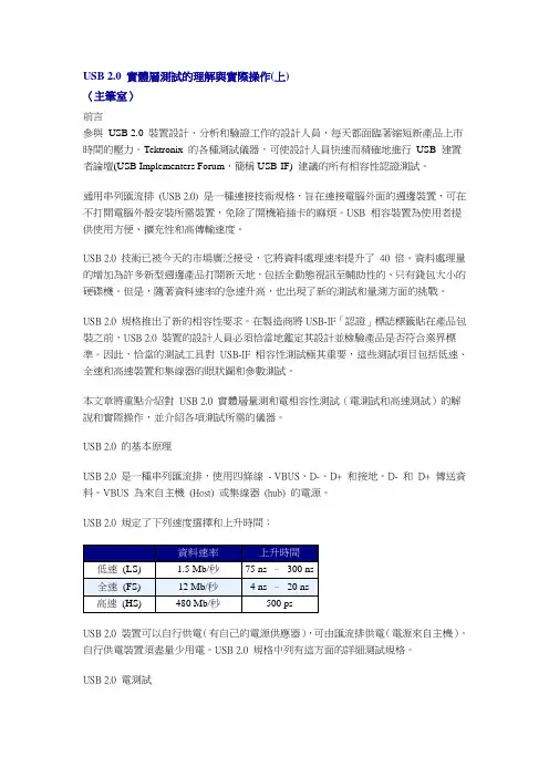
USB 2.0 的基本原理USB 2.0 是一種串列匯流排,使用四條線- VBUS、D-、D+ 和接地。
D- 和D+ 傳送資料。
VBUS 為來自主機(Host) 或集線器(hub) 的電源。
USB 2.0 規定了下列速度選擇和上升時間:USB 2.0 裝置可以自行供電(有自己的電源供應器),可由匯流排供電(電源來自主機)。
自行供電裝置須盡量少用電。
USB 2.0 規格中列有這方面的詳細測試規格。
USB 2.0 電測試USB 2.0 電測試包括訊號品質、峰值電流檢查以及壓降(Drop) 和浮動(Droop) 電壓測試。
Northern Tool + Equipment CO., INC. 产品说明书
Model: _______________ Purchase Date: _______________ Save the receipt, warranty and these instructions. It is important that you read the entire manual to become familiar with this product before you begin using it.
WARNING: Unqualified use and improve maintenance of this air compressor could result in serious personal injury. The following safety instructions should be operated to avoid any risk! Please read all of these instructions carefully and follow them.
1 OF 6
· Keep children and bystanders away while operating a compressor. Distractions can cause you to lose control, so visitors should remain at a safe distance from the work area.
WTV020-SD模块使用说明书V1.5
WTV020-SD 模块使用说明书
WTV020-Βιβλιοθήκη D 模块使用说明书本使用说明书使用亍 WTV020-SD-20S 和 WTV020-SD-16P 两种模块 目录
1、产品特征 ................................................................................................................................................................................................................ 3 2、产品概述 ................................................................................................................................................................................................................ 3 3、应用方框图 ............................................................................................................................................................................................................ 3 4、应用领域 ................................................................................................................................................................................................................ 4 5、封装引脚图 ............................................................................................................................................................................................................ 4
USB 2.0 卡片读写器说明书
USB 2.0 Card Reader/WriterVersion 1.0DESCRIPTION:The USB 2.0 Card Reader/Writer is an easily installed device, which only needs a USB interface to allow its use by any PC, Mac, or notebook computer. In addition, its mobility, strong data retention ability, and impressive appearance will provide you a brand new experience.Check your packing listing:USB2.0 Card Reader x 1Mini USB Cable x 1PS/2 to DC Jack Cable x 1 (or USB to DC Jack Cable x 1)Hardware Guide x 1CD driver x 1** If any of these items are missing from the product Retail package, contact your supplier immediately.Hardware SpecificationCompliant with USB specification version 2.0One Reader works with multiple media – Compact Flash, IBM Micro Drive, Smart Media, Multi Media Cards, SD Cards, and Memory Stick Looks like removable disk drive - drag and drop files between the digital media cards and the computerHigh transfer rate with USB interface: Full speed up to 60MB(480Mbits) per second.Support Windows 98/SE, Windows ME, Windows 2000, Windows XP and MAC 8.6 / 9.x.Card Reader Installation:Windows 98/SE1. Power on the computer where you will connect the USB2.0 Card Reader/Writer andmake sure the USB port is enabled and working properly (Please don’t plug your Card Reader/Writer into the USB port at this time).2. Insert the Driver CD into the CD-ROM drive. Run the Setup.exe program locatedwithin folder “SCR2061\Windows” of the Driver CD.3. The Install Shield Wizard will guide you through the installation process.4. Restart your computer to complete driver installation.5. Connect the ends of the USB extension cable into the Card Reader/Writer and theavailable USB port of your computer.6. Your computer will automatically recognize the Card Reader/Writer and show the“New Hardware Found” windows. Windows will install the files needed to use your device.7. Four Removable Disk drives with newly assigned drive letters will appear in MyComputer. The Card Reader/Writer is ready for use.Windows ME / Windows 2000/XPThe Card Reader/Writer is a driver-free device for Windows Me and Windows 2000/XP. You can connect it to an available USB port via the USB extension cable and don't have to install a special driver. Windows Me and Windows XP will detect the device and install all the associated files required for its use automatically.MAC O.S. 8.6 and 9.x1. Insert the Driver CD into the CD-ROM drive and double click the file SMSCInstaller.sit (under folder “SCR206\Mac” on the Driver CD).2. It will make “SMSC Installer” file.3. Double click it and it will install all associated files required for its.4. Restart computer.WarningNever remove or insert a memory card or disconnect the USB cable while data are being transmitted. To avoid improper shutdown, open the transmitted filefrom its new location to ensure transmission has been completed.。
USB-B1 v2 用户手册说明书
USB-B1 v2 User ManualV1.323/01/2018Table of Contents1.Introduction (2)1.1 Device Overview (2)1.2 System Overview (3)1.3 Features (3)1.4 Connectors (4)1.4.1 USB Connector (J1) (4)1.4.2 External Antenna Connector (J10) (5)1.4.3 External / PCB Antenna Selection Connectors J8 and J9 (5)1.4.4 IO and Peripheral Configuration Header (6)1.5 LEDs (6)2.Electrical Characteristics (7)2.1 Test Conditions (7)2.2 Absolute Maximum Ratings (7)2.3 Operating Conditions (7)2.4 GPIO (7)2.5 Antenna Output (8)2.6 Flash (8)2.7 IDAC (8)2.8 PWM (11)2.9 ADC (11)2.10 Comparator (11)3.Installation and operation (12)4.Mechanical Dimensions (13)1.Introduction1.1Device OverviewFeatures•Low cost RFID Reader with MifareClassic, Ultralight and NTAG2 support •LED indicator of a tag presence in the antenna field•Stand-alone mode (polling)•Command interface via USB COMPORT with optional AES-128encryption•UART baud rate up to 921600 bps•High transponder read and writespeed•-25°C to 85°C operating range• 4 configurable GPIOs with interrupts• 3 configurable PWMs•Comparator•ADC•Current Output DAC•AES-128 encryption engine•Multiple internal reference voltages•RoHS compliantApplications•Access control•Monitoring goods•Approval and monitoringconsumables•Pre-payment systems•Managing resources•Contact-less data storage systems •Evaluation and development ofRFID systems DescriptionThe USB-B1 v2 module is an expansion of the RFID B1 module - the second in an evolving family of 13.56 MHz sub assemblies from Eccel Technology Ltd (IB Technology). The product is designed with both embedded applications and computing / PLC platforms in mind. This product is an ideal design choice if the user wishes to add RFID capability to their design quickly and without requiring extensive RFID and embedded software expertise and time. An on board low power ARM microcontroller handles the RFID configuration setup and provides the user with a powerful yet simple command interface to facilitate fast and easy read/write access to the memory and features of the various transponders supported by this module.1.2System OverviewThe USB-B1 v2 device is an extension of our RFID B1 module. Below, In Figure 1-1 the System Diagram is presented.Figure 1-1 System Diagram1.3FeaturesTable 1-11.4ConnectorsMicro USB Connector (J1)External Antenna Connector (J10)External/PCB Antenna SelectionConnectors (J8 and J9)IO and PeripheralsConfiguration Header (J3)Picture 1-1In Picture 1-1 there are marked connectors available for the user when working with the USB-B1 v2 device. The connectors used on the USB-B1 v2 are described below.1.4.1USB Connector (J1)The device provides communication and power via USB connector J1. It is a micro USB Type B connector. The USB port, connected to the FTDI FT234XD chip provides USB to COM Port functionality. The user can configure the COM Port with a baud rate up to the maximum allowed by the RFID B1 module.1.4.2 External Antenna Connector (J10)The user has the option to work with an external RFID antenna connected to the USB-B1 v2 device. Connector J10 is where this should be connected. Eccel Technology Ltd provides a variety of RFID antennas which the user can use together with this device.1.4.3 External / PCB Antenna Selection Connectors J8 and J9To switch between the PCB antenna and an external antenna, two jumpers have to be used with the J8 and J9 connectors.We recommend using our external antennas from series RFID-ANT1356-50X50-xxx , where xxx is the cable length in mm. They have a read range of about 70mm, 50x50mm in size and 300 or 800mm cable length. We can also design antennas with higher read range and custom dimensions on request. More information about antennas: /antennas/J10 – External Antenna SocketJ8,J9 – Antenna selection header EXTERNAL ANTENNAREMARK: Also remove resistors: R13 and R14 J8,J9 – Antenna selection headerPCB ANTENNA1.4.4IO and Peripheral Configuration HeaderThe device PCB connects the pins on this header to all IOs and peripherals provided by the onboard RFID B1 module and a few pins are available providing +3.3V and GND signals.J3.1 – GPIO 0J3.2 – GPIO 2J3.3 – GPIO 1J3.4 – GPIO 3J3.5 – GNDJ3.6 – 3.3 VJ3.7 – IDAC (Digital to Analog Converter with current-type output)J3.8 – GNDJ3.9 – COMP (Comparator positive input)J3.10 – GNDJ3.11 – ADC (Analog to Digital Converter input)J3.12 – GNDJ3.13 – GNDJ3.14 – nRST (nRESET – reset input signal – active low)J3.15 – nSLEEP (Output signal indicating the device is in Sleep Mode or Power Down Mode – active low)J3.16 – nPWRDN (Power Down Request input signal – active low)1.5LEDsThere are 3 LEDs installed on the board. Each of them has its own functionality:•LED1– indicates that the reader is powered.•LED2– indicates data transmission via UART interface. The Functionality of LED2 can be configured in the internal MTP (Multiple-Time Programmable) memory of the FT234XD chip using the software utility FT_PROG which can be downloaded from the FTDI Utilities (click here).•LED3– indicates a tag presence in the reader antenna field.All of the LEDs are marked in green in Figure 4-1.2.Electrical Characteristics2.1Test ConditionsTypical device parameters were measured at an ambient temperature 22°C ±3°C and using a power supply of 5V ±5%.2.2Absolute Maximum RatingsTable 2-12.3Operating ConditionsTable 2-22.4GPIOTable 2-32.5Antenna OutputTable 2-4 2.6FlashTable 2-5 2.7IDACTable 2-6Figure 2-1 Source CurrentFigure 2-2 Sink Current2.8PWMTable 2-7 2.9ADCTable 2-8 2.10ComparatorTable 2-93.Installation and operationFrom the system and functionality point of view, the USB-B1 v2 device gives the same features as the RFID B1 module, and the user should refer to the RFID B1 User Manual when working with the USB-B1 v2. The FTDI chip expands the communication interface to the on-board RFID B1 module and allows the board to be connected to a computer and communicate with the device via a USB Com Port. Most systems have built-in drivers for such a Com Port.For a quick test, the user can connect the USB-B1 v2 to a computer and then start the B1-client application which allows the user to test all features of the device. The B1-client along with its user guide can be downloaded from here.HOSTUSB CableFigure 3-1 Connection to the host system.The best read range can be achieved when the tag is parallel to the surface of the reader.Figure 3-2 The correct way to read a RFID tagThe USB-B1 v2 can also operate in a stand-alone mode. The user can control all GPIO’s and add tags to the whitelist (a list of defined tags). For easy configuration of polling parameters we provide the B1 Stand-Alone Configurator application which can be downloaded from here. This application allows the user to simply search for a new tag, add it to the whitelist, configure polling parameters, enable/disable all of GPIOs and control them. For more information please refer to the RFID-B1 User Manual.Figure 3-3 The main window of the B1 Stand-alone Configurator4.Mechanical DimensionsDimensions in mm. All LEDs are marked with green circles.Figure 4-1No responsibility is taken for the method of integration or final use of the B1 based modules More information about the B1 module and other products can be found at the Internet site:or alternatively contact ECCEL Technology (IB Technology) by e-mail at:**************.uk。
- 1、下载文档前请自行甄别文档内容的完整性,平台不提供额外的编辑、内容补充、找答案等附加服务。
- 2、"仅部分预览"的文档,不可在线预览部分如存在完整性等问题,可反馈申请退款(可完整预览的文档不适用该条件!)。
- 3、如文档侵犯您的权益,请联系客服反馈,我们会尽快为您处理(人工客服工作时间:9:00-18:30)。
DM-TOOLS-USBICE2.0
用户手册
北京东方迪码科技有限公司
2008.3.10
目录
第一章安装说明 (4)
第二章注意事项 (9)
版本变更变更人Rev Date 变更描述
[0311/2008] Scott 0.1
第一章安装说明
DM-TOOLS-USBICE2.0性能强大,使用简单,通过阅读本章内容,您就可以迅速完成设备安装,进入使用环节。
1.1系统需求
主机: Pentium 500MHz以上处理器
内存: 512MB以上RAM
操作系统:Windows XP/2000,不支持Windows NT、98、ME
接口类型: USB
1.2操作指南
a)硬件连接步骤
i.用USB线将计算机和DM-TOOLS-USBICE2.0连接;
ii.将JTAG线将DM-TOOLS-USBICE2.0和目标板连接;注意JTAG接口中一个孔被堵住的和目标板连接,另一个与DM-TOOLS-USBICE2.0连接;
iii.为DM-TOOLS-USBICE2.0上电;
iv.第一次使用DM-TOOLS-USBICE2.0连接,上电后出现,选择“从列表或指定位置安装(高级)(S) ”(改图)
v.下一步,出现安装驱动程序页面,选择“不要搜索。
我要自己选择要安装的程序(D) 。
”
vi.选择“从软盘安装”
vii.点“浏览”,找到光盘中DM-TOOLS-USBICE2.0的安装驱动文件“DMUsbIce.inf”。
viii.正确加载驱动文件,点“下一步”后即可安装驱动文件。
b)软件连接步骤(以VisualDSP++5.0连接BF533芯片为例)
i.将“硬件连接步骤”完成后,给目标板上电
ii.打开VisualDSP++ Configurator软件,选择ADSP-BF533 EZ-KIT Lite
iii.在“Type”中选择“BF533USB EZ-KIT”,Device ID选择默认的0。
iv.设置后可在右边的窗口看到刚才的配置选项。
v.打开VisualDSP++ Environment软件,选择Session下的 New Session..。
vi.选择ADSP-BF533处理器。
vii.选择 EZ-KIT Lite。
viii.选择ADSP-BF533 EZ-KIT Lite Via Debug Agent,点Finish。
ix.正确完成上面的设置后,DM-TOOLS-USBICE2.0与目标板即可完成连接。
x.完成仿真或需要断开硬件连接时,请先切断目标板电源,再切断DM-TOOLS-USBICE2.0电源
第二章注意事项
2.1为确保产品使用寿命,请严格按照“安装说明”中的操作步骤进行硬件连接和软件连接;
2.2上电时,先给仿真器上电,再给目标板上电;
2.3断电时,先给目标板断电,再给仿真器断电;
2.4不要频繁采用拔插ICE电源接口的方式为其断电;
2.5在调试过程中,如需更换目标板,请先切断目标板电源,再将目标板上JTAG接口连接线断
开,DM-TOOLS-USBICE2.0电源可不必断开。
严禁目标板上电拔插JTAG接口,否则有可能烧毁目标板处理器和DM-TOOLS-USBICE2.0;
2.6为确保DM-TOOLS-USBICE2.0的高速运行,请使用与仿真器配套的电源适配器为仿真器供
电;严禁使用其他规格电源适配器,否则损坏不予保修;
2.7请勿剧烈撞击、震动、挤压、跌落本产品;
2.8请勿在很潮湿的环境下使用本产品,本产品不防水;。