PC792A1CC1-12C中文资料
C2310中文资料

C2310
Typical Applications
PCS Base Stations Land Mobile Radio Cellular Telephony Radio in the Local Loop
TCXO
Features
EFC Standard Standard Surface Mount Package Low Phase Noise option Low Profile STO50; STO50S3; STO50S3-01
v.2005-12-15 · page 1 of 5 Vectron international GmbH & Co. KG Landstrasse D-74924 Neckarbischofsheim Germany +49-07268-801-0 tel +49-07268-801-281 fax Vectron Asia Pacific Sales Office 1F-2F, No 8 Workshop, No 308 Fenju Road, WaiGaoQiao Free Trade Zone, Pudong, Shanghai, P.R. China 200131 +86 21 5048 0777 tel. +86 21 5048 1881 fax
Parameter Initial tolerance vs. supply voltage change vs. load change vs aging /15 Years overall tolerance
Typ
Note: * Stratum 3 per GR-1244-CORE: <±4.6 ppm for all causes and 20 years aging,Holdover: <±0.37 ppm over 24 hours (Code: D287 & B287)
人教版高中数学选择性必修第一册1.2第一课时空间向量基本定理

人A数学选择性必修1
返回导航 上页 下页
解析:A→C1=A→D+A→B+A→A1=A→D+2A→E+3A→F=xA→D+yA→E+zA→F, ∴x=1,y=2,z=3,故 x+y-z=0.
人A数学选择性必修1
返回导航 上页 下页
4.已知四面体 OABC,M,N 分别是棱 OA,BC 的中点,且O→A=a,O→B
返回导航 上页 下页
3.如图所示,已知空间四边形ABCD的每条边和对角线 长都等于1,点E,F,G分别是AB,AD,CD的中点, 计算:
人A数学选择性必修1
返回导航 上页 下页
(1)E→F·B→A; 解析:设B→A=a,B→C=b,B→D=c, {a,b,c}构成空间的一个基底,且|a|=|b|=|c|=1, 〈a,b〉=〈a,c〉=〈b,c〉=60°. (1)E→F·B→A=12B→D·B→A=12c·a=12×|c||a|·cos 60°=14.
人A数学选择性必修1
[解析] O→P=O→A+A→P=O→A+34A→N =O→A+34(O→N-O→A) =O→A+34O→N-34O→A=14O→A+34×23O→M =14O→A+12×12(O→B+O→C)=14O→A+14O→B+14O→C.
返回导航 上页 下页
人A数学选择性必修1
返回导航 上页 下页
=b,O→C=c,用 a,b,c 表示向量M→N,则M→N=___12_(_b_+__c_-__a_)______.
解析:M→N=O→N-O→M=12(O→B+O→C)-12O→A=12(b+c-a).
人A数学选择性必修1
返回导航 上页 下页
空间向量基本定理
1.定理 如果三个向量a,b,c不共面,那么对任意一个空间向量p,存在 __唯__一__的___有序实数组(x,y,z),使得p= xa+yb+zc .
C1210C3969PAC资料
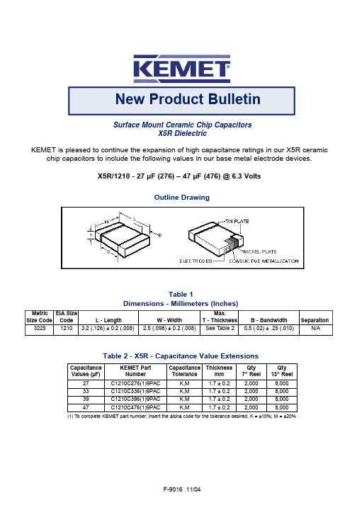
Surface Mount Ceramic Chip CapacitorsX5R DielectricKEMET is pleased to continue the expansion of high capacitance ratings in our X5R ceramicchip capacitors to include the following values in our base metal electrode devices.X5R/1210 - 27 µF (276) – 47 µF (476) @ 6.3 VoltsTable 1Dimensions - Millimeters (Inches)New Product BulletinOutline DrawingF-9016 11/04Table 2 - X5R - Capacitance Value ExtensionsMetric EIA Size Max.Size Code Code L - Length W - WidthT - Thickness B - Bandwidth Separation32251210 3.2 (.126) ± 0.2 (.008)2.5 (.098) ± 0.2 (.008)See Table 20.5 (.02) ± .25 (.010)N/A(1) To complete KEMET part number, insert the alpha code for the tolerance desired. K = ±10%; M = ±20%Capacitance Values (µF)KEMET Part Number Capacitance ToleranceThicknessmm Qty 7” Reel Qty 13” Reel 27C1210C276(1)9PAC K,M 1.7 ± 0.22,0008,00033C1210C336(1)9PAC K,M 1.7 ± 0.22,0008,00039C1210C396(1)9PAC K,M 1.7 ± 0.22,0008,00047C1210C476(1)9PACK,M1.7 ± 0.22,0008,000Electrical ParametersAs detailed in the KEMET Surface Mount Catalog F3102 for X5R, with following specific requirements based on room temperature (25°C) parameters:•Operating Range: -55°C to +85°C, with no-bias capacitance shift limited to ± 15% over that range •Insulation Resistance (IR) measured after 2 minutes at rated voltage @ 25°C: Limit is 500 megohm-microfarads.•Capacitance and Dissipation Factor (DF) measured at the following conditions. DF Limit is 10%.1 kHz and 1 Vrms if capacitance ≤10 µF120 Hz and 0.5 Vrms if capacitance > 10 µFSoldering ProcessThe 1210 components are suitable for reflow soldering only. All parts incorporate the standard KEMET barrier layer of pure nickel, with an overplate of pure tin to provide excellent solderability as well as resistance to leaching.MarkingThese chips are normally supplied unmarked. If required, they can be laser marked as an extra cost option. More detail on the marking format is included in our Surface Mount Catalog F3102. In general, the information in the KEMET Surface Mount catalog F3102 applies to these capacitors. The information in this bulletin supplements that in the catalog.© KEMET Electronics Corporation • P.O. Box 5928 • Greenville, SC 29606 • (864) 963-6300 • 。
8XC196MC中文资料

3
元器件交易网
8XC196MC
270946 – 2
NOTE The pin sequence is correct The 64-Lead SDIP package does not include the following pins P1 4 ACH12 P2 7 COMPARE3 P5 1 INST CLKOUT
Y
Y Y Y Y
Y
Y Y Y Y Y
Y
Y
The 8XC196MC is a 16-bit microcontroller designed primarily to control 3 phase AC induction and DC brushless motors The 8XC196MC is based on Intel’s MCS 96 16-bit microcontroller architecture and is manufactured with Intel’s CHMOS process The 8XC196MC has a three phase waveform generator specifically designed for use in ‘‘Inverter’’ motor control applications This peripheral allows for pulse width modulation three phase sine wave generation with minimal CPU intervention It generates 3 complementary non-overlapping PWM pulses with resolutions of 0 125 ms (edge trigger) or 0 250 ms (centered) The 8XC196MC has 16 Kbytes on-chip OTPROM ROM and 488 bytes of on-chip RAM It is available in three packages PLCC (84-L) SDIP (64-L) and EIAJ QFP (80-L) Note that the 64-L SDIP package does not include P1 4 P2 7 P5 1 and the CLKOUT pins Operational characteristics are guaranteed over the temperature range of b 40 C to a 85 C The 87C196MC contains 16 Kbytes on-chip OTPROM The 83C196MC contains 16 Kbytes on-chip ROM All references to the 80C196MC also refers to the 83C196MC and 87C196MC unless noted
CS19-12HO1中文资料
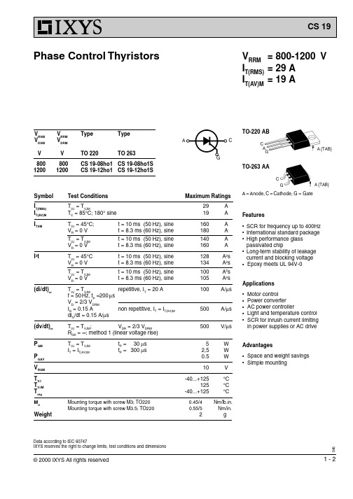
C
G
A (TAB)
A = Anode, C = Cathode, G = Gate
Features
q SCR for frequency up to 400Hz q International standard package q High performance glass
passivated chip q Long-term stability of leakage
f = 50 Hz, tP =200 µs
VD = 2/3 VDRM
I = 0.15 A
non repetitive, I = I
G
T T(AV)M
diG/dt = 0.15 A/µs
TVJ = TVJM;
VDR = 2/3 VDRM
R GK
=
∞;
method
1
(linear
voltage
rise)
I
G
=
0.1
A;
di /dt G
=
0.1
A/µs
≤
75 mA
≤
50 mA
≤
2 µs
RthJC RthCK
a
DC current DC current
Max. acceleration, 50 Hz
Dimensions in mm (1 mm = 0.0394") TO 263 AA
1.0 K/W typ 0.25 K/W
.340 .380 .280 .320
.380 .405 .270 .320 .100 BSC
.575 .625 .090 .110 .040 .055 .050 .070
0 .015
Agilent连接硬件配件文件说明书

Agilent Connectivity Hardware for PC-to-Instrument ConnectionsData Sheetwith Agilent GPIBInstrument Control ProductsIntroducing Agilent GPIB Instrument Control Products Agilent connectivity products enable:• Easy connection to GPIB instruments based on simple plug-and-play setup and configuration• Use of PC-standard interfaces that are prevalent even on notebook PCs, such as USB and LAN• A wide selection of interfaces to fit your test system application– PCI, PCIe®, USB and LAN• Use of industry-standard I/O libraries which makes integrationof existing instruments and software programs in a singlesystem easy, even if you use multiple instrument vendors.Table of ContentsConnecting is as easy as 1-2-3 (3)Agilent IO Libraries Suite 16.0 (4)Agilent 82357B USB/GPIB Interface Converter (5)Agilent 82350B High-Performance PCI GPIB Interface Card (6)Agilent 82351A High-Performance PCI Express® (PCIe)GPIB Interface Card (7)Agilent E5810A LAN/GPIB Gateway (8)Agilent GPIB Instrument Control Products Summary (9)Related Agilent Literature (10)Contact Agilent.........................................................................Back coverConnecting is as Easy as 1-2-3Establish a connection in less than 15 minutesAgilent IO Libraries Suite eliminates the many working hours it takes to connect and configure PC-controlled test systems, especially if it involves instruments from multiple vendors. In fact, with IO Libraries, connecting your instruments to a PC is as easy as connecting a PC to a printer. Easily mix instruments from different vendorsAgilent IO Libraries Suite eliminates headaches associated with trying to combine hardware and software from different vendors. The software is compatible with GPIB, USB, LAN and RS-232 test instruments that adhere to the supported interface standards, no matter who makes them.When you install the IO Libraries Suite, the software checks for the presence of other I/O software on your computer. If it finds another ven-dor’s VISA libraries, it automatically installs in a side-by-side mode that allows you to use the existing I/O software and the Agilent software together in multi-vendor systems.Work in the environment that’s comfortable to youIn addition, the IO Libraries are compatible with a variety of applica-tion development environments and programming APIs including Agilent or NI VISA, VISA COM, SICL, Agilent 488 (compatible with NI-488.2), and Agilent VEE. There is flexibility to choose the software and hardware of your choice to get your job done. Works with millions of existing instruments from hundreds of vendorsAgilent connectivity products and IO Libraries are trusted and known for their reliability. The IO Libraries ships with more than 150 instruments from Agilent Technologies. If you already own an Agilent connectivity product or instrument, you can download the latest version of Agilent IO Libraries Suite for free.Agilent IO Libraries Suite 16.0PC softwareOperating system• Windows® 7 32-bit and 64-bit (Starter, Home Basic, Home Premium, Professional, Ultimate,Enterprise)• Windows Vista® SP1 and SP2 32-bit and 64-bit (Home, Home Premium, Business, Ultimate,Enterprise Editions)• Windows XP Pro or Home edition service pack 3 or later, 32-bit onlyPC hardwareProcessor600 MHz class (800 MHz or greater recommended)RAM• Windows XP: 256 MB minimum (1 GB or greater recommended)• Windows Vista or Windows 7: 1 GB minimumHard disk space required 1.5 GBDisplay800 x 600, 256 colorsVB6VISA COM, VISA, SICL, Agilent 488, Excel VBAC/C++, Managed C++VISA COM, VISA, Agilent 488.NET languages (, C#)VISA COM, VISA, Agilent 488LabVIEW VISA, Agilent 488MATLAB VISANote: Agilent IO Libraries Suite supports VEE Pro program development with drivers and/or Direct IO.Connection Expert Automatically scans and configures your instrument IO, helps you get connected quickly and easilyand displays the status of your interfaces and instrumentsInteractive IO Lets you quickly send commands to instruments and read responsesIO Monitor Lets you monitor and debug I/O calls made on any of Agilent’s supported buses using Agilent SICL,VISA, VISA COM, or Agilent IVI instrument drivers (released after September 18, 2010)IO control Provides easy access to the IO Libraries Suite from the Windows system trayviFind32Debug utility uses VISA functions to find resources and lists them in a console windowSee the following URL for more information or for the latest updates: /find/iosuiteAgilent 82357B USB/GPIB Interface ConverterFeatures• Fast and easy connection to GPIB instruments • Uses standard USB and IEEE-488 interfaces • Maximum GPIB transfer rate of 1.15 MB/s • Parallel polling capabilityBest for• Easiest GPIB connectivity • Notebook computer GPIB connectionConnect GPIB instruments quickly and easily to your computer’s USB portThe Agilent 82357B USB/GPIBinterface provides a direct connection from the USB port on your desktop and laptop computers to GPIB instru-ments. Once the software is loaded, your computer automatically detects the 82357B when it is connected to the USB port of the computer.The 82357B is a plug-and-play device. It is also hot-pluggable, making it easy to connect and disconnect without having to shut down thecomputer. No external power supplies are necessary.The 82357B USB/GPIB interface implements USB 1.1 (12 Mbits/s) and is compatible with USB 2.0. The 82357B USB/GPIB interface uses a thin, flexible, high-quality USB cable that is USB 2.0-compliant. The USB cable is shielded, and the connector is specified to 1,500 insertions, ensur-ing a durable connection and reliabledata transfer.Includes Agilent IO Libraries Suite and VISA/SICL programming manuals on CD-ROM AccessoriesNoneBoosting performance with simplest connectivityAgilent 82350B High-Performance PCI GPIB Interface CardFeatures• PCI IEEE-488 interface for PCs • Transfer rates up to 900 KB/s • Dual processor support on the latest Windows operating systemBest for• Maximum GPIB throughput for all configurationsHigh performance formanufacturing test applicationsThe 82350B is Agilent’s highest-performance GPIB interface. With a direct PCI computer connection, transaction overhead is minimized for the best overall performance.The 82350B card de-couples GPIB transfers from PCI bus transfers. Buffering provides connectivity and system performance that is superior to direct memory access (DMA). The hardware is software-configurable and compatible with the plug-and-play standard for easy hardware installation. The GPIB interface card plugs into a 5 volt PCI slot in thebackplane of your PC.Includes Agilent IO Libraries Suite and VISA/SICL programming manuals on CD-ROMAccessoriesGPIB cables/adapter (see page 9)This traditional GPIB connection still offers the highest throughputAgilent 82351A High-Performance PCI Express ® (PCIe) GPIB Interface CardFeatures• Compact half-height size (68.9 mm)• High transfer rate of 1.4 MB/s • High flexibility via up-plugging (to x4 or x8 PCIe slots)• 3.3 V signal level for lower power consumptionBest for• Bandwidth-intensive PC applications • Adding GPIB connection for PCIe based PCs or workstationsHigh transfer rate fordemanding test applicationsThe Agilent 82351A PCIe-GPIB interface card is designed forintegration into next generation PCs or workstations. It offers fast data transmission for various demanding test applications that require data to be transferred to memory fast enough without any loss or overwriting. PCIe (PCI Express) is an evolutionary version of PCI that offers a higher transfer rate across a low number of wires. It is also backward-compatible with PCI software, so you don’t need to perform any code re-configuration. The powerful bus architecture of PCIe allows bidirectional data transmis-sion, and the implementation of anew class of test applications.Includes Agilent IO Libraries Suite and VISA/SICL programming manuals on CD-ROMAccessoriesGPIB cables/adapter (see page 9)New standard for high-speed internal devicesAgilent E5810A LAN/GPIB GatewayFeatures• Remote access and control of GPIB instruments via LAN • Easy setup and use via digital display and web browserBest for• Connection to remote GPIB and RS-232 instrumentation • Shared test systemsRemote access and collaboration with GPIB instruments via your LANThe E5810A can use DHCP, if avail-able, to automatically configure nec-essary network parameters, including its IP address. The gateway can be controlled from multiple locations and by multiple users via your LAN, so it is easy to share control of instru-ments from locations worldwide.For easy remote access, enter the IP address from the digital display as the URL in your web browser and gain access to connected GPIB and RS-232 instruments. Then use your browser to send instrument com-mands interactively, and quickly see your measurement results. Use the digital display and LEDs to check the IP address and troubleshoot locally.System useFor system environments, the E5810A gateway can be mounted on a rack. The rack mount kit (Option 100) allows two devices to be placed side-by-side in one rack width. With its built-in power supply, there are noadditional power modules to mount.Includes Agilent IO Libraries Suite and VISA/SICL programming manuals on CD-ROMAccessories• GPIB cables/adapter (see page 9)• Rack Mount Kit (Option 100)Take advantage of LAN technology for your GPIB instruments and test systemsAgilent GPIB Instrument Control Products Summary CablesAgilent also offers a variety of cables that provide easy and reliable connec-tions. Agilent cables are engineered for exceptional reliability and durability, even under the harshestconditions.Cable Length 10833D GPIB cable0.5 meter 10833A GPIB cable 1 meter 10833B GPIB cable 2 m10833C GPIB cable 4 m10833F GPIB cable 6 m10833G GPIB cable8 mAdaptersThe 10834A GPIB-to-GPIB adapter can help when limited rear-panel space and other design consider-ations make cabling difficult. The 10834A adapter extends the first cable by 2.3 cm away from the rear panel to provide clearance for other connectors, switches, and cables.GPIB board82350B PCI/GPIB card• GPIB connection for PCI-based PCs orworkstations• Maximum throughput for allconfigurations up to 900 KB/s82351A PCIe/GPIB card• GPIB connection for PCIe-based PCsor workstations• High throughput applications up to1.4 MB/sUSB converter82357B USB/GPIB card• GPIB connectivity, even for notebookcomputers• Easiest GPIB instrument set-up to PC LAN converter E5810A LAN/GPIBgateway• Connection to remote GPIB andRS-232 instruments• Test-system sharing and collaborationamong multiple usersCable10833x GPIB cables• Connection between GPIBinstruments (daisy-chain)• Connection from GPIB instrument tothe PCI/GPIB or PCIe/GPIB card• Connection from GPIB instrument tothe LAN/GPIB gatewayAdapter10834A GPIB-to-GPIBadapter• 2.3-cm clearance at GPIB instrument’srear panelTypical configurations of PC-to-instrument connectionRelated Agilent LiteratureThis article is the fourth of a series of four application notes with System Developers in mind. It explains with great depth how you can simplify test integration by taking advantage of open connectivity standards. Meet your throughput requirements yet stay within budget.Where to download: /find/gpibAgilent Email Updates/find/emailupdates Get the latest information on the products and applications you select.LAN eXtensions for Instruments puts the power of Ethernet and the Web inside your test systems. Agilent is a founding member of the LXI consortium.Agilent Channel Partnersw w w /find/channelpartners Get the best of both worlds: Agilent’s measurement expertise and product breadth, combined with channel partner convenience. AdvancedTCA ® Extensions for Instrumentation and Test (AXIe) is an open standard that extends the AdvancedTCA ® for general purpose and semiconductor test. Agilent is a founding member of the AXIe consortium.PCI eXtensions for Instrumentation (PXI) modular instrumentation delivers a rugged, PC-based high-performance measurement and automation system.Agilent Advantage Services is com-mitted to your success throughout your equipment’s lifetime. We share measurement and service expertise to help you create the products that change our world. To keep you com-petitive, we continually invest in tools and processes that speed up calibra-tion and repair, reduce your cost of ownership, and move us ahead of your development curve./quality/find/advantageservicesFor more information on AgilentTechnologies’ products, applications or services, please contact your local Agilent office. The complete list is available at:/find/contactus Americas Canada (877) 894 4414 Brazil (11) 4197 3500Mexico 01800 5064 800 United States (800) 829 4444Asia Pacific Australia 1 800 629 485China 800 810 0189Hong Kong 800 938 693India 1 800 112 929Japan 0120 (421) 345Korea 080 769 0800Malaysia 1 800 888 848Singapore 180****8100Taiwan 0800 047 866Other AP Countries (65) 375 8100 Europe & Middle East Belgium 32 (0) 2 404 93 40 Denmark 45 70 13 15 15Finland 358 (0) 10 855 2100France 0825 010 700**0.125 €/minuteGermany 49 (0) 7031 464 6333 Ireland 1890 924 204Israel 972-3-9288-504/544Italy39 02 92 60 8484Netherlands 31 (0) 20 547 2111Spain 34 (91) 631 3300Sweden0200-88 22 55United Kingdom 44 (0) 118 9276201For other unlisted Countries:/find/contactusRevised: October 14, 2010Product specifications and descriptions in this document subject to change without notice.© Agilent Technologies, Inc. 2011Printed in USA, May 6, 20115989-1889ENPCIe and PCI Express are US registered trademarks and/or service marks of PCI-SIG.Windows, Windows Vista and Microsoft are trademarks or registered trademarks of Microsoft Corporation in the United States and/or other countries.。
高中数学同步教学课件 空间向量基本定理的初步应用

解析:根据“―O→M =x―O→A +y―O→B +z―O→C ,若 x+y+z=1,则点 M 与
点 A,B,C 共面”,因为 2+(-1)+(-1)=0≠1,1+1+(-1)=1,
1+12+13=161≠1,12+13+16=1,由上可知,B、D 满足要求.
答案:BD
2.如图所示,正方体 ABCD-A1B1C1D1 的棱长为 1,E,F,G,G1 分别是棱 CC1,BC,CD,A1B1 的中点.求证:
1.2 第2课时 空间向量基本定理的初步应用
【典例精析】
题型一 证明平行、共面问题 [例 1] 如图,已知正方体 ABCD-A′B′C′D′,E,F 分别为 AA′和 CC′ 的中点.求证:BF∥ED′.
[证明] ―B→F =―BC→+―C→F =―BC→+12―CC→′ =―AD→+12―DD→′ , ―ED→′ =―EA→′ +―A′D→′=12―AA→′ +―AD→=12―DD→′ +―AD→, ∴―B→F =―ED→′ ,∴―B→F ∥―ED→′ , ∵直线 BF 与 ED′没有公共点,∴BF∥ED′.
题型二 求解夹角、证明垂直问题 [例 2] 如图所示,在三棱锥 A-BCD 中,DA,DB,DC 两两垂直, 且 DB=DC=DA=2,E 为 BC 的中点.
(1)证明:AE⊥BC; (2)求直线 AE 与 DC 的夹角的余弦值.
[解] (1)证明:因为―A→E =―D→E -―D→A =12(―D→B +―D→C )-―D→A , ―C→B =―D→B -―D→C ,所以―A→E ·―C→B =21―D→B +12―D→C -―D→A ·(―D→B -―D→C ) =12―D→B 2-12―D→C 2-―D→A ·―D→B +―D→A ·―D→C , 又 DA,DB,DC 两两垂直,且 DB=DC=DA=2, 所以―A→E ·―C→B =0,故 AE⊥BC.
CDE-121C 说明书

ALPINE ELECTRONICS MARKETING, INC.1-1-8 Nishi Gotanda,Shinagawa-ku,Tokyo 141-0031, JapanPhone 03-5496-8231ALPINE ELECTRONICS OF AMERICA, INC.19145 Gramercy Place, Torrance,California 90501, U.S.A.Phone 1-800-ALPINE-1 (1-800-257-4631)ALPINE ELECTRONICS OF CANADA, INC.777 Supertest Road, Toronto,Ontario M3J 2M9, CanadaPhone 1-800-ALPINE-1 (1-800-257-4631)ALPINE ELECTRONICS OF AUSTRALIA PTY. LTD.161-165 Princes Highway, Hallam Victoria 3803, Australia Phone 03-8787-1200ALPINE ELECTRONICS GmbH Wilhelm-Wagenfeld-Str. 1-3, 80807 München, Germany Phone 089-32 42 640ALPINE ELECTRONICS OF U.K. LTD.Alpine House Fletchamstead Highway, Coventry CV4 9TW, U.K.Phone 0870-33 33 763ALPINE ELECTRONICS FRANCE S.A.R.L.(RCS PONTOISE B 338 101 280)98, Rue de la Belle Etoile, Z.I. Paris Nord Il,B.P . 50016, 95945 Roissy Charles de GaulleCedex, France Phone 01-48638989ALPINE ITALIA S.p.A.Viale C. Colombo 8, 20090 Trezzano Sul Naviglio (MI), Italy Phone 02-484781ALPINE ELECTRONICS DE ESPAA, S.A.Portal de Gamarra 36, Pabelln, 3201013 Vitoria (Alava)-APDO 133, Spain Phone 945-283588ALPINE ELECTRONICS (BENELUX) GmbH Leuvensesteenweg 510-B6,1930 Zaventem, Belgium Phone 02-725-13 15••用戶手冊請在使用本設備之前先閱讀用戶手冊。
- 1、下载文档前请自行甄别文档内容的完整性,平台不提供额外的编辑、内容补充、找答案等附加服务。
- 2、"仅部分预览"的文档,不可在线预览部分如存在完整性等问题,可反馈申请退款(可完整预览的文档不适用该条件!)。
- 3、如文档侵犯您的权益,请联系客服反馈,我们会尽快为您处理(人工客服工作时间:9:00-18:30)。
Automotive Plug-In / PC B Power Relay
FEATURES
Most popular automotive relay
1 A and 1 C contact forms ava ilable
40 Amps continuous carrying c apacity
Contact switching capacity up to 120 Amps Up to 125 degrees C operating temperature Internal diodes or resisto rs available
PC792A
Max. Switching Voltage 75 VDC
1 Form A or 1 Form C
CONTACT RATINGS
CHARACTERISTICS
Operate Time 7 ms. typical Release Time Insulation Resistance 5 ms. typical
100 megohms min, at 500VDC, 50%R H Dielectric Strength 500 Vrms, 1 min. between coil and contacts Shock Resistance 20 g, 11ms, functional; 200 g, destructive
Vibration Resistance Power Consumption 1.6 W approx.
Ambient Temperature Range -40 to 85 degrees C operating, -40 to 125 degrees C for Class F Weight
31 grams approx.
ORDERING INFORMATION
Example:
PC792A Model
-12Sockets available from Picker C omponents
Parallel Component
-1C CONTACT DATA
Material
Initial Contact Resistance Service Life
Mechanical Electrical
AgSnInO (Silver Tin Indium Oxide)100 milliohms max @ 0.1A, 6VDC 1 X 10⁷
2 X 10⁵Operations Operations
Normally Open Nil: None; D: Diode; R: Resistor; N: N ickle Plated Terminals
Coil Voltage
-C1Contact Form
Max Switching Current Break 40 Amps
Make 120 Amps 60 Amps (at 20 degrees C)Max. Continuous Current Minimum Load
0.1 A @ 12 VDC
-RN
Drop Resistance 1 Meter height drop on concrete in final enclosu re Normally Closed Break 30 Amps
Make 45 Amps 40 Amps (at 20 degrees C)Case Style
C: Plug-In; P: PCB; C1: Plastic Bracket; C 2: Metal Bkt DA 1.27 mm, 10 - 40 Hz; 40-70 Hz: 5 g; DA 0.5mm, 70-100 Hz; 100-500 Hz: 10 g.S Enclosure
C: Dust Cover, S: Sealed Case
Contact Form
1A, 1C or 1U (1 form A with 2 #87 Termin als) 40 Amps (at 85 degrees C)
30 Amps (at 85 degrees C)
PC792A
PC792A
REFERENCE CURVES
COIL DATA
Coil Voltage
624
Resistance
ohms + 10%
Must Operate
Voltage Max.
(VDC)Must Release Voltage Min.
(VDC)Continuous Voltage Max.
(VDC)2290330
7.214.3
1.2
2.4
20.539.1
_ 3.60.610.112(17.9)
.705(8.4)
.331(16.9)
.665(8.0)
.31587
87A
3085
86
(17.9)
.705(8.4)
.331(16.9)
.665(8.0)
.31587
87A 30
85
86
(1.2 X 2.4).047 X .094All Holes
30
85Wiring Diagrams
30
85Form 1U
Form 1A
Form 1C
Dimensions in Inches (millimet ers)Plug-In Type
Bottom View PC Board Layout
Tolerances +.010 unless otherwise noted
Notes:
Maximum make current refers to inrush of a lamp load In 85 degree C ambient reduce maximum coil volt age to 72%
Plug-In Case (C) and PCB Case (P)
(24.5)
.965(26.5)
1.04(26.5)
1.04(6.3)
.250(11.5)
.453(0.8)
.03150
55606570758085909510011
12131415161718
AT 20 C
o
AT 85 C
o
AT 125 C
o
Coil Temp Rise Contacts Carrying 40A
T e m p e r a t u r e R i s e C
o
40506070809010011
12131415161718
20A
30A 35A 40A Coil Temp Rise
Ambient Temp 20 C
o
C o i l T e m p e r a t u r e R i s e C
o
Coil Applied Voltage
Coil Applied Voltage
1210203530501001
23101005203050N.O. Contact N.C. Contact
Maximum Switching Capacity at 85 C Arc Extinguished Resistive Loads
Switching Voltage(VDC)
S w i t c h i n g C u r r e n t (A m p s )
o
PC792A PC792A
(22.0)
.866
(16.0)
.630
(24.5)
.965
(6.0)
.236
(6.4)
.252 Dia.
(26.5)
1.04
(26.5)
1.04
(4.2)
.165
(26.5)
1.04
(26.5)
1.04
(16.0)
.630
(24.5)
.965
(15.0)
.591
(6.0)
.236
(5.3)
.210 Dia.
(4.6)
.181
(13.3)
.524
(18.0)
.709
(7.0)
.275
.252 Dia.
(6.4)
(20.6)
.811
(45.3)
1.78
(36.0)
1.42
(36.0)
1.42
(10.4)
.409
Molded Plastic Bracket (C1)
Bent Metal Bracket (C3)
Metal Bracket (C2)
Skirted Case with Metal Bracke t (C4)
Skirted Case with Bent Metal B racket (C5)。