4117-22AZ24VDC中文资料
EtherNet IP直接输入型步进电机控制器(伺服24VDC)系列JXC91 安装与维护手册说明书

Installation & Maintenance Manual EtherNet/IP Direct input typeStep Motor Controller (Servo 24VDC)Series JXC91This manual contains essential information for the protection of users and others from possible injury and/or equipment damage.•Read this manual before using the product, to ensure correct handling,and read the manuals of related apparatus before use.•Keep this manual in a safe place for future reference.•These instructions indicate the level of potential hazard by label of "Caution", "Warning" or "Danger", followed by important safety information which must be carefully followed.•To ensure safety of personnel and equipment the safety instructions in this manual and the product catalogue must be observed, along with other relevant safety practices.WarningWarningThe compatibility of the product is the responsibility of the person who designs the equipment or decides its specifications.Since the product specified here is used under various operatingconditions, its compatibility with specific equipment must be decided by the person who designs the equipment or decides its specifications based on necessary analysis and test results.The expected performance and safety assurance of the equipment will be the responsibility of the person who has determined its compatibility with the product.This person should also continuously review all specifications of the product referring to its latest catalog information, with a view to giving due consideration to any possibility of equipment failure when configuring the equipment.Only personnel with appropriate training should operate machinery and equipment.The product may become unsafe if handled incorrectly.The assembly, operation and maintenance of machines or equipment must be performed by an operator who is appropriately trained and experienced.Do not attempt to service or replace product and machinery/equipment until safety is confirmed.1. The inspection and maintenance of machinery/equipment should only be performed after measures to prevent falling or runaway of the driven objects have been confirmed.2. When the product is to be removed, confirm that the above safety measures are implemented and the power from any appropriate source is cut, and read and understand the specific product precautions of all relevant products carefully.3. Before machinery/equipment is restarted, take measures to prevent unexpected operation and malfunction.CautionThe product is provided for use in manufacturing industries.The product herein described is basically provided for peaceful use in manufacturing industries.If considering using the product in other industries, consult SMC beforehand and provide specifications or a contract, if necessary.If anything is unclear, contact your nearest sales branch.Refer to the operation manual on the SMC website (URL ).Contact SMC beforehand and take special consideration of safety measures if the product is to be used in any of the following conditions:1. Conditions and environments outside of the given specifications, or use outdoors or in a place exposed to direct sunlight.2. Installation on equipment in conjunction with atomic energy, railways,air navigation, space, shipping, vehicles, military, medical treatment,combustion and recreation, or equipment in contact with food and beverages, emergency stop circuits, clutch and brake circuits in press applications, safety equipment or other applications unsuitable for the standard specifications described in the product catalog.3. An application which could have negative effects on people, property, or animals requiring special safety analysis.4. Use in an interlock circuit, which requires the provision of doubleinterlock for possible failure by using a mechanical protective function,and periodical checks to confirm proper operation.WarningThe Communication cable must be connected to a PC using a USB cable through a conversion unit.Do not connect the teaching box to a PC.Do not use LAN cable to connect to the controller, as this may cause damage to the personal computer.2 Product configurationTo P1, P2∗1∗1●ControllerOptionsPLCTo SIPCorEtherNet/IP Controller power supply 24VDC•Power supply plug (Included)<Applicable wire size>AWG20 (0.5mm )•Communication cable •Conversion unit•Controller set up kit (Controller settingsoftware, communication cable, conversion unit,USB cable are included)Part No: LEC-W2•Teaching box(3m cable is provided.)Product number:LEC-T1-3□G□•USB cable (A-mini B type)∗1 These items are included when ordered using the part number for an actuator set.∗2 The latest version of the controller setting software must be used.Upgrade software can be downloaded from SMC website./Electric actuatorTo ENCTo MOT To PWRLED displayRefer to the table below for the details of the LED status.∗2CautionDo not turn OFF the input power supply for the controller or disconnect and connect the cable while the data is being written to EEPROM (PWR LED (green) is flashing).∗Possibility of incorrect/corrupted data (step data, parameter)•Actuator cable(Robotic type cable)Model number:•LE-CP-□-□(Robotic type cable)•LE-CP-□-□-S (Standard cable)•Conversion cable Product no.:P5062-5(2) GroundingPlace the grounding cable with crimped terminal between the M4 screw and shakeproof washer as shown below and tighten the screw.Refer to the operation manual on SMC website (URL ).CautionThe M4 screw, cable with crimped terminal and shakeproof washer must be prepared by the user.The controller must be connected to Ground to reduce noise.URL (Global) (Europe)Specifications are subject to change without prior notice from the manufacturer.© 2016 SMC Corporation All Rights Reserved13 ContactsAUSTRIA (43) 2262 62280-0NETHERLANDS (31) 20 531 8888 BELGIUM (32) 3 355 1464 NORWAY (47) 67 12 90 20 CZECH REP.(420) 541 424 611 POLAND (48) 22 211 9600 DENMARK (45) 7025 2900 PORTUGAL (351) 21 471 1880FINLAND (358) 207 513513 SLOVAKIA (421) 2 444 56725 FRANCE (33) 1 6476 1000 SLOVENIA (386) 73 885 412GERMANY (49) 6103 4020 SPAIN (34) 945 184 100 GREECE (30) 210 271 7265 SWEDEN(46) 8 603 1200 HUNGARY (36) 23 511 390 SWITZERLAND (41) 52 396 3131 IRELAND (353) 1 403 9000 UNITED KINGDOM(44) 1908 563888ITALY(39) 02 92711BULGARIA (359) 2 974 4492ESTONIA (372) 651 0370 ROMANIA (40) 21 320 5111LATVIA (371) 781 77 00 LITHUANIA(370) 5 264 8126 12 TroubleshootingRefer to the operation manual on the SMC website (URL ).(1) MountingThe controller can be direct mounted using screws or mounted on a DIN rail.Details of the controller mounting options are shown below.Mounting directionBasic specifications[1] Direct mounting (JXC917-□)(Mounting with two M4 screws)Mounting directionGround wire[2] DIN rail mounting (JXC918-□)(Mounting with DIN rail)Hook the controller on the DIN rail andpress lever A in the direction of the arrow to lock it.Ground wireBefore locked onto DIN railLocked onto DIN railGround wireDIN railACable with crimping terminal M4 screwShakeproof washerControllerPower supply plug specificationsThe specifications of the power supply plug supplied with the controller are shown below.Power supply plugIP address×Manual setting of IP address8 Initial Setting methodSetting of switch (IP address)Turn OFF the power supply while setting the switch.The rotary switch should be set with a small flat blade screwdriver.Refer to the operation manual on the SMC website (URL ).。
pilz安全继电器工作原理

安全继电器是由数个继电器与电路组合而成,为的是要能互补彼此的异常缺陷,达到正确且低误动作的继电器完整功能,使其失误和失效值愈低,安全因素则愈高,因此需设计出多种安全继电器以保护不同等级机械,主要目标在保护暴露於不同等级之危险性的机械操作人员。
安全继电器与一般继电器的主要差别在哪里所谓“安全继电器”并不是“没有故障的继电器”,而是发生故障时做出有规则的动作,它具有强制导向接点结构,万一发生接点熔结现象时也能确保安全,这一点同一般继电器完全不同。
安全继电器用在何处呢用在带有确认机器安全的输入,确认安全后,给接触器等的输入进行控制的安全电路的设计上。
Q:对安全电路的要求1、在紧急停止解除时,机器不能出现突然再启动2、万一机器安全电路发生故障时,可以停止机器动力电源3、安全电路发生故障时,机器不能再启动像安全开关、光幕等确认安全的输入,无法做到上述功能,那么,怎样才能做到安全电路呢?时候双重电路就可以了?A:单靠双重化是不行的。
双重化是必要的,但是除此之外,比备如下几个条件,双重化电路的互相检查,确认所有安全电路已经断开一次,必要时由作业者操作便可以启动等条件。
还有从另一个角度来说,输入的开关接线短路或电线外皮破损而引起的接地的可能性时,必须预防因此而引起的机器突然启动。
实际上,为了方便安全电路的构成,将安全继电器和其他组件组合配套,把基本的紧急停止电路、安全电路组成电路模块的产品称为安全继电器模块。
皮尔兹安全继电器PNOZX124VDC工作原理安全继电器顾名思义要安全,它是一个安全回路中所必须的控制部分(安全回路包括安全输入,控制器,安全输出),安全继电器接受了安全输入(比方说安全光幕、安全门锁)通过内部回路的判断,确定性的输出开关信号到设备的控制回路里。
它的输入输出一般都是冗余的,并且触点都是强制导向的开关。
其实安全继电器说白了就是把2-4个继电器混在了一起,各自的触点很多是互锁的,这样就可以有效地监控外部回路的触点是否熔接,或者有没有短路等现象。
IZMX Series 空气电路切换器说明书

2Versatile circuit breakersup to 4000 A – for cost-effective,optimized solutions.The IZMX16 of the NRX series is the smallest air circuit-breaker (ACB) worldwide:With a volume of only 0.024 m³ and a front surface of only 0.092 m², it is just slightly bigger than the size of a A4 sheet of paper! And all this without any loss in terms of performance.The innovative concept allows the user to install two circuit breakers side by side in withdrawable design, in a 600 mm wide section . This fact provides for a more cost-effective setup of thesection and, in addition, it helps to save operating space. And where remote switching is required, this volume can even accommodate a motor for charging the stored-energyspring mechanism and releases for electrical operation.High performance combined with reduced space is excep-tional value to customer.The IZMX40 of the NRX series is a circuit breaker for up to 4000 A with depth less than 400mm for the drawout version, without the need to install any additional “copper mines” in the connection area.Tests to integrate it into Eaton switchgear systems, such as Modan, xEnergy, Power Xpert and Capitol 40 confirm itsoutstanding technical data and optimal compatibility thanks to the flexible connection system.The modular structure,integrated solutions as well as a complete range of accessories and additional functions make it easy to adapt the circuit breaker to any of the required applica-tions. Optionally it can beconfigured right at the factory – without any extra cost for additional installation work at the circuit breaker.Horizontal TerminalVertical Terminal (Available on B, N and H type.E type can be configured ashorizontal terminal only)3The next generation trip unitplatform: Power Xpert Release (PXR)PXR Trip Unit• LCD display with multilingual capability • Current metering on PXR20 and power metering on PXR25• Extended range for pickup value and delay timing setting • "OFF" setting available for ground fault(G) andnon-delayed instantaneous trip(I)• Onboard Modbuscommunication(standard on PXR25 and optional on PXR20)• MicroUSB for computer connection • PXR Configuration and Test Tool to remotely configure and test the trip unit • Trip test• Waveform capture • Diagnostics• Long trip curve setting • ZSI/Thermal Memoryon/offProfi bus-DP Modbus EthernetOnboard ModbusIncreased operating safetyand flexibility based on communicationWith the respective communi-cation module - PCAM, MCAM or ECAM (Profibus-DP /Modbus/ Ethernet Communica-tions Adapter Module) - every circuit breaker of the NRX series is equipped for modern communication and is fit for the future. The databus not only allows to transmit information, but also to receive commands/settings.Onboard Modbus communica-tion is standard on the PXR25 (U type) trip unit and optional on the PXR20(V type) trip unit upon order. Additional PCAM,MCAM or ECAM module canbe installed externally forPXR25 to expand the communi-cation capability. (No more than one external CAM module can be installed)4Arcflash Reduction Maintenance System™Important functions and characteristicsEaton’s patented Arcflash Reduction Maintenance System technology provides mainte-nance staff improved safety of downstream maintenance locations using a simple and reliable method to reduce fault clearing times and energy in an arc flash event (radiation, sound, pressure, temperature). Arcflash Reduction Maintenance System uses a separate analog trip circuit providing faster signal processing and interruption times than the standard (digital) “instantaneous” protection.The Arcflash Reduction Maintenance System function is activated either directly on the circuit breaker through a local switch or remotely through communications or a contact input.Arcflash Reduction Mainte-nance System is optional on both PXR20 and PXR25 trip units.Zone selectivity ZSICircuit breakers are directly connected to a signal line, without any additional modules. So, in case of a malfunction, they ensure that only the circuit breaker immediately upstream the point of failure will break a short-circuit without delay.The advantage of the zone selectivity feature - compared to ordinary time selectivity - is the significantly reduced time until switch-off and the reduced amount of energy released in case of a short-circuit.For additional safety of maintenance staff we recom-mend combining ZSI functional-ity with Arcflash Reduction Maintenance System.Easy maintenanceand serviceMaintenance and service canbe conveniently performed onthe draw-out breaker as theprimary finger clusters (blue)and levering mechanism arepart of the breaker instead ofthe cassette.Eaton also offers many fieldinstallable accessories andparts, extending the life of thebreaker.Breaker rear side (Drawout parent breaker)5Trip unit specificationsTechnical dataIZMX16IEC/EN 60947IZMX40Rated Current (I n )630A, 800A, 1000A, 1250A, 1600A 800A, 1000A, 1250A, 1600A, 2000A, 2500A, 3200A, 4000A (E type:800A~2000A only )Type of circuit breakerB N H B N H Rated impulse withstand voltage (U imp , VAC)1200012000Rated insulation voltage (U i , VAC)10001000Rated operational voltage (U e , VAC)690120001000690120001000690690120001000690120001000690Ultimate breaking capacity (I cu , kA)240V 50/60Hz 4285856685105480V 50/60Hz 4250666685105690V 50/60Hz 424242667575Rated service breaking capacity (I cs , kA)240V 50/60Hz 4250656685105480V 50/60Hz 4250506685105690V 50/60Hz 424242667575Rated short-time withstand current (I cw , kA)1s/3s42/-42/-42/-66/5385 1)/6685 1)/66Rated short-circuit making capacity (I cm , kA)480V 50/60Hz 88105145145187231690V 50/60Hz 888888145165165E1200010004806666666666/-145Lifespan630A-1600A 800A-1600A 2000A 2500A-4000A Mechanical, w/o maintenance 12500125001000010000Mechanical, w/ maintenance 25000250002000020000Electrical, w/o maintenance10000100008000 2)6000 3)Dimensions (H × W × D, mm)Fixed 3P 338 × 210 × 184398 × 376 × 298Fixed 4P338 × 279 × 184398 × 492 × 298Withdrawable 3P 360 × 254 × 289456 × 426 × 393Withdrawable 4P 360 × 324 × 289456 × 541 × 393Weight (kg)Fixed 3P/4P15/2045/56Withdrawable 3P/4P39/4798/121PXRVStandard - current IZMX16/40…V…PXRUUniversal - power IZMX16/40…U…Protective optionsLSI, LSIG LSI, LSIG Overload protection (L)Overload trip (I r )(0.4 ~ 1.0) × I n (0.4 ~ 1.0) × I n Long delay time t r (6 × I r )0.5 ~ 24s 0.5 ~ 24s Short-time delayed short-circuit protection (S)Short delayed pickup (I sd )(1.5 ~ 10) × I r (1.5 ~ 10) × I r Short delay time, flat characteristic curve (t sd )0 ~ 0.5s 4)0 ~ 0.5s 4)Short delay time at 8 × I r , I²t curve (t sd )0.1 ~ 0.5s 0.1 ~ 0.5s Non-delayed short-circuit protection (I)Non-delayed pickup (I i )OFF, (2 ~ 15) × I nOFF, (2 ~ 15) × I nOptional ground fault protection (G)Ground/Earth fault alarm (A)Optional Optional Ground/Earth pickup (I g )OFF, (0.2 ~ 1.0) × I n OFF, (0.2 ~ 1.0) × I n Short delay time, flat characteristic curve (t g )0.1 ~ 0.5s 0.1 ~ 0.5s Short delay time at 0.625 x I n , I²t curve (t g )0.1 ~ 0.5s 0.1 ~ 0.5sStandard functionsCurrent measurement, status/Overload LED, cause of trip LEDs, over-temperature trip, thermal memory, zone selectivity ZSI, closing releases MCR, LCD displayVoltage/power/energy measurement, waveform capture, communication(Modbus), trip logOptional functions1) 75kA at 690VAC2)6000 operations for B,N and H type at 690VAC, E type at 480VAC 3)2500 operations at 690VAC 4)50ms delay when setting at "0"5)Arcflash Reduction Maintenance System™Communication, Arcflash ReductionMaintenance System™ 5)Additional communication module, Arcflash Reduction Maintenance System™ 5)IZMX system overviewUnique parts and accessories for -IZMX16Interchangeable accessories betweenIZMX16 and IZMX4067123456789101112131415161718192021222324512336349IZMX16, INX16, IZMX40, INX40Unique parts and accessories for IZMX40IZMX Circuit-breaker IZMX16: 630 - 1600A IZMX40: 800 - 4000ACassette for withdrawable units +IZMX-CAS163-1600 X16, 1600A, 3P +IZMX-CAS164-1600 X16, 1600A, 4P +IZMX-CAS403-2000 X40, 2000A, 3P +IZMX-CAS404-2000 X40, 2000A, 4P +IZMX-CAS403-2500 X40, 2500A, 3P +IZMX-CAS404-2500 X40, 2500A, 4P +IZMX-CAS403-3200 X40, 3200A, 3P +IZMX-CAS404-3200 X40, 3200A, 4P +IZMX-CAS403-4000 X40, 4000A, 3P +IZMX-CAS404-4000 X40, 4000A, 4P Main terminal kitsUniversal terminals, 3- and 4-pole horizontal/verticalIZMX-THV163-2 X16, 3P IZMX-THV164-2 X16, 4PIZMX-THV403-3200-2 X40, 3P, 3200A IZMX-THV404-3200-2 X40, 4P, 3200A IZMX-TH403-2 X40, 3P, 4000A, horizontal IZMX-TV403-2 X40, 3P, 4000A, vertical IZMX-TH404-2 X40, 4P, 4000A, horizontal IZMX-TV404-2 X40, 4P, 4000A, vertical Safety Shutter+IZMX-SH163 X16, 3P +IZMX-SH164 X16, 4P +IZMX-SH403 X40, 3P +IZMX-SH404 X40, 4PMotor operatorAutomatic charging of the spring force storage for remote or local operations +IZMX-M16-24DC X16, 24VDC +IZMX-M16-110AD X16, 110VAC/DC +IZMX-M16-230AD X16, 220VAC/DC +IZMX-M40-24DC X40, 24VDC +IZMX-M40-110AD X40, 110VAC/DC +IZMX-M40-230AD X40, 110VAC/DC Current sensor for neutral conductorCurrent sensor for sensing the neutral-conductor current.IZMX-CT16-N-2 X16IZMX-CT40-N-2 X40Levering toolLev-in tool to move the breaker in and out of the cassette. Standard Omega shaped handle is included in D/O breaker. Optional collapsible handle can be ordered separatelyPosition cell switchesCell switch signals the position of the breaker inside of the cassette.Connect, Test and Disconnect Position.IZMX-CS16-1-2 X16IZMX-CS40-L-2 X40, left IZMX-CS40-R-2 X40, rightDoor escutcheonCloses the gap between Breaker and Switchgear-door.IP41 included in breaker For IP55:IZMX-DC16-W-2 X16IZMX-DC40-W-2 X40Communication modules External modulesIZMX-MCAM-2 Modbus IZMX-ECAM-2 Ethernet IZMX-PCAM-2 Profibus DP Control circuit terminal units Modular designLatch check switch For external application Usage +IZMX-LCSLatch check switchFor use with closing release.+IZMX-LCS-SRClosing releasesCloses the breaker by an electrical signal.+IZMX-SR24DC 24VDC +IZMX-SR110AD 110AC/DC +IZMX-SR230AD 220AC/DC Key lockingLocking of the breaker by a keylock.IZMX-KLP-SO-CES-2IZMX-KLP-SO-KIRK-2IZMX-KLP-SO-RONIS-2IZMX-KLP-SO-CASTELL-2Shunt releasesOpens the breaker by an electrical signal.+IZMX-ST24DC 24VDC +IZMX-ST110AD 110VAC/DC +IZMX-ST230AD 220VAC/DC Undervoltage releasesOpens the breaker by a voltage-drop in the control circuit.+IZMX-UVR24DC 24VDC +IZMX-UVR110AD 110VAC/DC +IZMX-UVR220AD 220VAC/DC +IZMX-UVR400AC 380VAC Red-pop trip indicatorRed-pop trip indicator signals a trip by the trip unitIncluded in breaker with trip unit Trip indicator switchesOvercurrent trip switch (OTS) signals a trip by the trip unit.+IZMX-OTSSwitching operations counters Counts the number of operations.+IZMX-OCAuxiliary contacts Signaling switch ON-OFF.2a2b standard. 4a4b maximum for IZMX16 and 12a12b for IZMX40+IZMX-AS22 X16/X40, add 2a2b +IZMX-AS44 X40, add 4a4b +IZMX-AS66 X40, add 6a6b +IZMX-AS88 X40, add 8a8b +IZMX-AS1010 X40, add 10a10b Locking facilities Plastic or metalIZMX-PLPC16-P-2 X16, plastic IZMX-PLPC16-M-2 X16, metal IZMX-PLPC40-P-2 X40, plastic IZMX-PLPC40-M-2 X40, metal Trip unitPXR20, V-type, current metering C - Onboard ModbusG - Ground fault protectionM - Arcflash Reduction Maintenance System™+IZMX-PXRV-C +IZMX-PXRV-G +IZMX-PXRV-GC +IZMX-PXRV-GM +IZMX-PXRV-GMCTrip unitPXR25, U-type, power metering +IZMX-PXRU-G +IZMX-PXRU-M +IZMX-PXRU-GMEaton CorporationAsia Pacific HeadquarterNo.3, Lane 280, Linhong Road,Changning District, Shanghai 200335Tel: 86-21-52000099Fax: 86-21-52000200© 2015 Eaton Corporation All Rights Reserved July 2015Eaton is a registered trademark of Eaton Corporation.All trademarks are property of their respective owners.Selection guideBreaker catalog numberRecommended selection examplesIZMX16 fixed 220VAC motorized example (EO2):*IZMX16B3-V16F +IZMX-M16-230AD +IZMX-ST230AD +IZMX-SR230AD +IZMX-AS22 +IZMX-OTS *IZMX-THV163-2 EASY400-POW Fixed breaker, including 2a2b Aux contact 220-240 VAC/DC Charging motor 220-240 VAC/DC Shunt trip 220-240 VAC/DC Closing spring release Additional 2a2b Aux contact (4a4b total)Over current trip switch(OTS) 2CO Main terminal adapter - horizontal External power module to converter 220VAC to24VDC to power trip unitIZMX40 fixed 220VAC motorized example (EO2):*IZMX40B3-V16F +IZMX-M40-230AD +IZMX-ST230AD +IZMX-SR230AD +IZMX-AS22+IZMX-OTS *IZMX-THV403-3200-2EASY400-POW * Manually Operated(MO) componentsOption for ground fault protection:• Add +IZMX-PXRV-G (V type trip unit) or +IZMX-PXRU-G(U type trip unit) for ground fault protection• For 3-pole ACB, external neutral censor is recommended for ground fault protection. Order IZMX-CT16-N-2 (IZMX16) or IZMX-CT40-N-2 (IZMX40)Fixed parent breaker, including 2a2b Aux contact 220-240 VAC/DC Charging motor 220-240 VAC/DC Shunt trip 220-240 VAC/DC Closing spring release Additional 2a2b Aux contact (4a4b total)Over current trip switch(OTS) 2CO Main terminal adapter – horizontal (3200A and below)External power module to converter 220VAC to 24VDCto power trip unitIZMX16 withdrawable 220VAC motorized example (EO2):*IZMX16B3-U16W+IZMX-M16-230AD+IZMX-ST230AD+IZMX-SR230AD+IZMX-AS22+IZMX-OTS*+IZMX-CAS163-1600*+IZMX-SH163*IZMX-THV163-2EASY400-POWWithdrawable parent breaker, including 2a2b Aux contact 220-240 VAC/DC Charging motor 220-240 VAC/DC Shunt trip 220-240 VAC/DC Closing spring release Additional 2a2b Aux contact (4a4b total)Over current trip switch(OTS) 2CO Cassette(including interphase barriers and handle)Safety shutters Main terminal adapter - horizontal External power module to converter 220VAC to 24VDC to power trip unit IZMX40 withdrawable 220VAC motorized example (EO2):*IZMX40B3-U16W +IZMX-M40-230AD +IZMX-ST230AD +IZMX-SR230AD +IZMX-AS22+IZMX-OTS *+IZMX-CAS403-2000*+IZMX-SH403*IZMX-THV403-3200-2EASY400-POW Withdrawable parent breaker, including 2a2b Aux contact 220-240 VAC/DC Charging motor 220-240 VAC/DC Shunt trip 220-240 VAC/DC Closing spring release Additional 2a2b Aux contact (4a4b total)Over current trip switch(OTS) 2CO Cassette(2000A and below)Safety shutters Main terminal adapter – horizontal (3200A and below)External power module to converter 220VAC to 24VDC topower trip unitThe technical data and parameters are subject to change before the official launch. Please confirm with Eaton when placing the order.Product Type IZMX = Air circuit breaker INX = Switch disconnectorSwitching CapacityE = Economy: (IZMX40E:66kA@440VAC)B = Basic: (IZMX16B:42kA, IZMX40B:66kA)N = Normal: (IZMX16N:50kA, IZMX40B:85kA)H = High: (IZMX16H:66kA, IZMX40H:105kA)Trip Unit Type V = Selective-current U = Universal-power P = ProfessionalMounting Form W F = Withdrawable = FixedConfigurationBlank = Basic breaker MO = Manually operatedEO2 = 220VAC electrically operated Rated CurrentIZMX1606 = 600A 12 = 1250A IZMX4008 = 800A 16 = 1600A 32 = 3200A E type: 800~2000A only08 = 800A 16 = 1600A 10 = 1000A 20 = 2000A 40 = 4000A 10 = 1000A12 = 1250A 25 = 2500APoles = 3 pole = 4 pole34IZMX 16B 4-V 16W EO2Frame Size 16 = 630A-1600A 40 = 800A-4000A。
Z4系列直流电机规格参数

mH 5.3 18.9 37.5 3.65 13.5 26 3.4 9.8 19.4 3.15 10.4 2.7 17.7 2.07 8.3 15.2 5.8 17.6 25 1.16 4.65 9.3 15.7
% 85 85.9 79.4 80.9 71.9 74.5 87.8 88.3 81.2 83.4 75.6 77.7 88.2 88.6 83.6 84.7 79.4 80.5 87.4 88.5 80.4 82.6 88.2 89.1 77.9 79.4 89.1 90.2 84.7 85.7 79.1 81.7 84.7 86.5 75.5 78.1 73 74.1 89.5 90.7 85.8 87 82.2 83.7 77.3 79.7
1.72
350
型号 Z4-180Type 22/21
额定 功率 PN kW 16.5 18.5 33
额定转速 400V 440V
弱磁 转速 nF r/min 1600 2000 1250 3200 3000 2000 3000 2000 1600 1000 3000 1000 3200 2800 2000 1400 1200 750 3000 2000 1300 1200 1000
Z4-132-1
650
1.309 2.56 0.226
0.32
140
Z4-132-2
73C
0.811 1.565 0.1905
0.4
Байду номын сангаас160
Z4-132-3
800
0.531 0.976 0.1835
0.48
180
Z4-16011
37 19.5 22 40.5
820 58.8 113 920 50.5 137 77.8 59.1 95.4 51.4 42.4 185 115 79 61 1400 1200 1050 0.862 0.097 0.376 0.675 0.29 0.947 1.264 0.0555 0.2125 0.419 0.756 0.593 0.1426
AZM 170-02ZRKA 24 VAC DC 电磁锁断路器说明书

26.10.2016 06:10:11hDatasheet AZM 17002ZRKA 24 VAC/DCSolenoid interlock / AZM 170 Preferred typ(Minor differences between the printed image and the original product may exist!)• Thermoplastic enclosure • Doubleinsulated • Compact design• 90 mm x 84 mm x 30 mm • 1 Cable entry M 20 x 1.5• Interlock with protection against incorrect locking.• Long life• High holding force• IDC method of termination • Manual releaseOrdering detailsProduct type description AZM 17002ZRKA 24 VAC/DC Article number 101141020EAN code 4030661120294eCl@ss 27272603ApprovalApprovalBG USA/CAN CCCClassificationStandards EN ISO 138491B 10d Opener (NC) 2.000.000Mission time 20 Y earsnoticeGlobal PropertiesProduct name AZM 170StandardsEN 6094751, BGGSET19Compliance with the Directives (Y/N) Y esNumber of actuating directions2 pieceActive principle electromechanicalDuty cycle Magnet 100 %Materials Material of the housings Plastic, glassfibre reinforced thermoplastic, selfextinguishing Material of the contacts SilverHousing coating NoneWeight278 gMechanical dataDesign of electrical connection IDC method of terminationCable section Min. Cable section1 x 0,75 mm² Max. Cable section1 x 1.0 mm², flexibleMechanical life> 1.000.000 operationsEmergency unlocking device (Y/N)NoManual release (Y/N)Y es bottomEmergency release (Y/N)NoLatching force30 NPositive break force17 Npositive break travel11 mmClamping force F1000 NMax. Actuating speed2 m/sAmbient conditionsAmbient temperature Min. environmental temperature−25 °C Max. environmental temperature+60 °CProtection class IP67 to IEC/EN 60529Electrical dataDesign of control element Opener (NC)notice changeover contact with double break, type Zb or 2 NCcontacts, with galvanically separated contact bridges Switching principle Creep circuit elementNumber of auxiliary contacts0 pieceNumber of safety contacts2 piecePower to unlock NoPower to lock Y esRated control voltage U s24 VAC/DCPower consumption max. 10 WRated impulse withstand voltage U imp4 kVRated insulation voltage U i250 VThermal test current I the10 AUtilisation category AC15: 230 V / 4 A, DC13: 24 V / 4 AMax. fuse rating6 A gG DfuseATEXExplosion protection categories for gases NoneExplosion protected category for dusts NoneMiscellaneous dataApplicationssliding safety guard,removable guard,hinged safety guardDimensionsDimensions of the sensor Width of sensor90 mm Height of sensor84 mm Length of sensor30 mmnoticeThis type termination (IDC) method enables simple connetion of flexible conductors without the need for the use of conductor ferrules Individual coding available on requestManual release• For manual release using M5 triangular key, available as accessoryDiagramNote Diagrampositive break NC contactactiveno activeNormallyopen contactNormallyclosed contactSwitch travel diagramNotes Switch travel diagramContact closedContact openSetting rangeBreak pointPositive opening sequence/ angleVS adjustable range of NO contactVÖ adjustable range of NC contactN after travelOrdering suffixThe applicable ordering suffix is added at the end of the part number of the safety switch.Order example: AZM 17002ZRKA 24 VAC/DC1637...16370,3 µm goldplated contacts...ST2431connector M12 , Individual solenoid monitoringOrdering codeAZM 170(1)(2)Z(3)K(4)(5)(6)(7)(1)without IDC method of terminationSK Screw connection(2)111 Normally open contact (NO) / 1 Opener (NC)022 Opener (NC)12/0.01 Normally open contact (NO), 2 Opener (NC) / (3)without Latching force 5 NR Latching force 30 NI Individual coding(4)without Power to unlockA Power to lock(5)without cable glandST Connector M12 x 1ST2431Connector M12 x 1, Individual solenoid monitoring(6)24VAC/DC U s 24 VAC/DC110VAC U s 110 VAC230VAC U s 230 VAC(7)without Manual release2197Manual release from side (Power to unlock)1637goldplated contactsAZM 170ST and AZM 170SKAZM 170ST(1)Z(2)K(3)(4)(5)024AZM 170SK(1)Z(2)K(3)(4)(5)024(1)11/111 Normally open contact (NO), 1 Opener (NC) / 1Normally open contact (NO), 1 Opener (NC) 11/021 Normally open contact (NO), 1 Opener (NC) / 2Opener (NC)12/001 Normally open contact (NO), 2 Opener (NC) / 12/111 Normally open contact (NO), 2 Opener (NC) / 1Normally open contact (NO), 1 Opener (NC) 12/021 Normally open contact (NO), 2 Opener (NC) / 2Opener (NC)02/012 Opener (NC), / 1 Opener (NC), 02/102 Opener (NC), / 1 Normally open contact (NO), (2)without Latching force 5 NR Latching force 30 N(3)without Power to unlockA Power to lock(4)1637goldplated contacts(5)2197Manual release for Power to unlockDocumentsOperating instructions and Declaration of conformity (fr) 611 kB, 29.04.2016 Code: mrl_azm170_frOperating instructions and Declaration of conformity (de) 595 kB, 25.04.2016 Code: mrl_azm170_deOperating instructions and Declaration of conformity (it) 645 kB, 09.04.2010 Code: mrl_azm170_itOperating instructions and Declaration of conformity (nl) 720 kB, 23.09.2010 Code: mrl_azm170_nlOperating instructions and Declaration of conformity (en) 611 kB, 25.04.2016 Code: mrl_azm170_enOperating instructions and Declaration of conformity (jp) 843 kB, 23.08.2016 Code: mrl_azm170_jpOperating instructions and Declaration of conformity (pl) 590 kB, 11.02.2015 Code: mrl_azm170_plOperating instructions and Declaration of conformity (da) 582 kB, 07.08.2012 Code: mrl_azm170_daOperating instructions and Declaration of conformity (es) 609 kB, 22.06.2016 Code: mrl_azm170_esBGtest certificate (en) 260 kB, 09.12.2015Code: z_m17p02BGtest certificate (de) 257 kB, 09.12.2015Code: z_m17p01CCC certification (en) 933 kB, 16.08.2016Code: q_371p02CCC certification (cn) 932 kB, 16.08.2016Code: q_371p03EAC certification (ru) 809 kB, 05.10.2015Code: q_6040p17_ruImagesDimensional drawing (basic component)Assembly exampleDetail photoSystem componentsActuator101122893 AZ 17/170B1• Particularly suitable for sliding doors101137406 AZ 17/170B12245• Particularly suitable for sliding doors • Damps vibration on guard device101122895 AZ 17/170B5• Particularly suitable for sliding doors101139788 AZ 17/170B11• Particularly suitable for sliding doors101139789 AZ 17/170B15• Particularly suitable for sliding doors101123391 AZM 170B6• Particularly suitable for hinged guards• For very smal actuating radii• The direction of actuation can be selected by applicable insertionof the insertAccessories101208493 AZM 170B CENTERING GUIDE• for AZ 17 and AZM 170101100887 TRIANGULAR KEY TKM5• For manual release using M5 triangular key, available asaccessory• For maintenance, installation, etc.ConnectorAK4M12• Prewired cable• 4pole• Connector without cable• 4poleK.A. Schmersal GmbH & Co. KG, Möddinghofe 30, D42279 WuppertalThe data and values have been checked throroughly. Technical modifications and errors excepted.Generiert am 26.10.2016 06:10:12h Kasbase 3.2.5.F.64I。
使用说明书 合众电气

HZGZ-711电缆寻点、故障定位仪使用手册武汉市合众电气设备制造有限公司欢迎使用武汉市合众电气设备制造有限公司产品尊敬的顾客感谢您使用本公司的产品。
在您初次使用设备前,请您详细地阅读本使用说明书,将可帮助您熟练地使用我公司设备。
我们的宗旨是不断地改进和完善公司的产品,因此您所使用的设备可能与使用说明书有少许的差别。
如果有改动的话,我们会用附页方式告知,敬请谅解!您有不清楚之处,请与公司售后服务部联络,我们定会满足您的要求。
由于试验设备均有可能带电压,您在插拔测试线、电源插座时,会产生电火花,小心电击,避免触电危险,注意人身安全!◆慎重保证本公司生产的产品,在发货之日起三个月内,如产品出现缺陷,实行包换。
三年内如产品出现缺陷,实行免费维修。
三年以上如产品出现缺陷,实行有偿终身维修。
如有合同约定的除外。
◆安全要求请阅读下列安全注意事项,以免人身伤害,并防止本产品或与其相连接的任何其它产品受到损坏。
为了避免可能发生的危险,本产品只可在规定的范围内使用。
只有合格的技术人员才可执行维修。
—防止火灾或人身伤害使用适当的电源线。
只可使用本产品专用、并且符合本产品规格的电源线。
正确地连接和断开。
当设备连线处联机状态时,请勿随意连接或断开测试导线。
产品接地。
本产品除通过电源线接地导线接地外,产品外壳的接地柱必须接地。
为了防止电击,接地导体必须与地面相连。
在与本产品做联机试验前,应确保本产品已正确接地。
注意所有终端的额定值。
为了防止火灾或电击危险,请注意本产品的所有欢迎使用武汉市合众电气设备制造有限公司产品额定值和标记。
在对本产品进行连接之前,请阅读本产品使用说明书,以便进一步了解有关额定值的信息。
请勿在无产品盖板时操作。
如盖板或面板已卸下,请勿操作本产品。
使用适当的保险丝。
只可使用符合本产品规定类型和额定值的保险丝。
避免接触裸露电路和带电金属。
产品有电时,请勿触摸裸露的接点和部位。
在有可疑的故障时,请勿操作。
如怀疑本产品有损坏,请本公司维修人员进行检查,切勿继续操作。
欧姆龙继电器表

28.
D4MC-5020
触点:1开1闭,10A 250VAC机械寿命:1000万次滚珠按钮式
29.
D4MC-5000
触点:1开1闭,10A 250VAC机械寿命:1000万次方式:柱塞式
30.
D4MC-2020
触点:1开1闭,10A 250VAC机械寿命:1000万次下压式合页式滚珠短摆杆型
24.
D4NA-412G
触点:1开1闭,10A 250VAC机械寿命:1000万次可调滚珠摆杆型
25.
D4NA-4132
触点:1开1闭,10A 250VAC机械寿命:1000万次滚珠柱塞型
26.
D4NA-4131
触点:1开1闭,10A 250VAC机械寿命:1000万次柱塞型
27.
D4MC-5040
触点:1开1闭,6A 250VAC机械寿命:1500万次撞压式
21.
D4D-2121N
触点: 1开1闭,6A 250VAC机械寿命:1000万次撞压式,高度可调
22
D4D-2132N
触点:1开1闭,6A 250VAC机械寿命:1000万次撞压式,滚轮柱塞型
23.
D4NA-4122
触点:1开1闭,10A 250VAC机械寿命:1000万次滚珠摆杆型
17.
SHL-Q2155
触点:1开1闭,10A 250VAC机械寿命:1000万次交叉滚轮柱塞型
18.
SHL-W2155
触点:1开1闭,10A 250VAC机械寿命:1000万次枢轴滚轮手柄型
19.
SHL-W255
触点:1开1闭,10A 250VAC机械寿命:1000万次枢轴滚轮短手柄型
四方综保电动机说明书
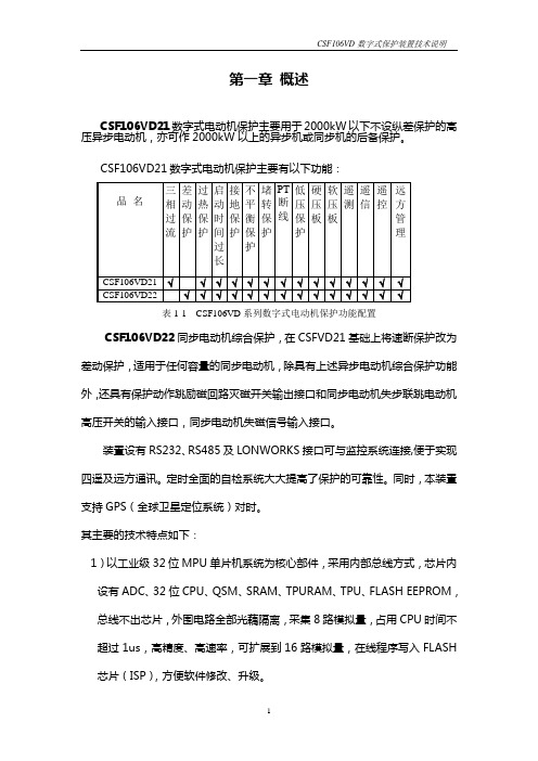
第一章概述CSF106VD21数字式电动机保护主要用于2000kW以下不设纵差保护的高压异步电动机,亦可作2000kW以上的异步机或同步机的后备保护。
表1-1 CSF106VD系列数字式电动机保护功能配置CSF106VD22同步电动机综合保护,在CSFVD21基础上将速断保护改为差动保护,适用于任何容量的同步电动机,除具有上述异步电动机综合保护功能外,还具有保护动作跳励磁回路灭磁开关输出接口和同步电动机失步联跳电动机高压开关的输入接口,同步电动机失磁信号输入接口。
装置设有RS232、RS485及LONWORKS接口可与监控系统连接,便于实现四遥及远方通讯。
定时全面的自检系统大大提高了保护的可靠性。
同时,本装置支持GPS(全球卫星定位系统)对时。
其主要的技术特点如下:1)以工业级32位MPU单片机系统为核心部件,采用内部总线方式,芯片内设有ADC、32位CPU、QSM、SRAM、TPURAM、TPU、FLASH EEPROM,总线不出芯片,外围电路全部光藕隔离,采集8路模拟量,占用CPU时间不超过1us,高精度、高速率,可扩展到16路模拟量,在线程序写入FLASH芯片(ISP),方便软件修改、升级。
2)128×64点大液晶全汉字显示,调试全部为汉字菜单结构,使用方便、直观、信息详尽丰富。
3)采用工业级芯片,表面贴工艺,体积小,抗震、抗干扰能力强、可靠性高。
4)前面板232串口带光电隔离,可在现场实现通讯,提供更加方便友好的调试操作环境。
5)结构上设计合理,全封闭机箱坚固、抗震、抗干扰能力强,机箱小巧,适合安装于保护屏、开关柜等处。
6)该保护共可录入4套保护定值,便于现场运行。
7)可扩展工业级CAN总线,LON总线网络,组网方便、经济、可靠、可与监控系统直接通讯。
8)自动记录故障数据,掉电不丢失,便于事故分析。
9)线路故障时,除提供光报信号外,保护自动弹出全中文故障报告,直观明了,便于维护。
- 1、下载文档前请自行甄别文档内容的完整性,平台不提供额外的编辑、内容补充、找答案等附加服务。
- 2、"仅部分预览"的文档,不可在线预览部分如存在完整性等问题,可反馈申请退款(可完整预览的文档不适用该条件!)。
- 3、如文档侵犯您的权益,请联系客服反馈,我们会尽快为您处理(人工客服工作时间:9:00-18:30)。
元器件交易网
Features
Twin structure of 4117 type. Small size, light weight. Low coil power consumption.
PC board mounting.
Ordering Information
Dimensions (Unit: mm)
Dimensions
Mounting (Bottom views)
mm 0.3 1.4 2.1 2.4 3.81 4.0 5.08 8.89 10.16 18 20 29.6
>àçÇá
0.012 0.055 0.083 0.094 0.150 0.157 0.200 0.350 0.400 0.709 0.787 1.165
Max. 3.9 6.5 7.8 11.7 15.6 23.4 31.2 9y2 25y2 36y2 85y2 145 y2 324y2 576y2
CAUTION: 1.The use of any coil voltage less than the rated coil voltage will compromise the operation of the relay.
Dash numbers
Coil resistance ±10%
Coil power consumption W
Operate Time ms
Release Time ms
Rated 003-1000 005-1000 006-1000 009-1000 012-1000 018-1000 024-1000 3 5 6 9 12 18 24
4117-2 2C S 12VDC
1 2 3 4 3 Enclosure:S: Sealed type;Z: Dust cover 4 Coil rated Voltage(V):DC:3,5,6,9,12,18,24 1 Part number:4117-2 2 Contact arrangement:2A:2A;2C:2C; 2U:2U;2W:2W
Coil Parameter
Coil voltage VDC Pickup voltage VDC(max) (75%of rated voltage ) 2.25 3.75 4.50 6.75 9.00 13.5 18.0 release voltage VDC(min) (10% of rated voltage) 0.3 0.5 0.6 0.9 1.2 1.8 2.4 2y1.0 10 5
-40~85 85% (at 40) 20g
IEC68-2-3Test Ca
Qualification inspection:
Perform the qualification test as specified in the table of IEC255-19-1 and minimum sample size 24.
2.Pickup and release voltage are for test purposes only and are not to be used as design criteria.
117
Ambient Temperature Relative Humidity 元器件交易网 Mass
Wiring diagram(Bottom views)
NOTES 1).Dimensions are in millimeter.
2).Inch equivalents are given for general information only.
Reference Data
Contact Data
Contact Arrangement Contact Material Contact Rating (resistive) Max. Switching Power Max. Switching Voltage Contact Resistance or Voltage drop Operation Electrical life Mechanical 2A DPSTNO f2C DPDT(B-M) f2U DPSTNODM f2W DPDTNC-NO AgNi Ag SnO2 AgCdO 2Af2C: 10A/120VAC,28VDC ; 2Uf2W: 2×10A/120VAC, 28VDC 280W 1200VA 75VDC 380VAC Max. Switching Current:10A 50m Item 3.12 of IEC255-7 105 Item 3.30 of IEC255-7 107 Item 3.31 of IEC255-7