LDS-A404RI, 规格书,Datasheet 资料
LDSBus Trailing Edge Light Dimmer Datasheet说明书

LDSBus Trailing Edge Light Dimmer DatasheetVersion 1.0Document Reference No.: BRT_000380 Clearance No.: BRT#1901 Introduction1.1 FeaturesNeither the whole nor any part of the information contained in, or the product described in this manual, may be adapted or reproduced in any material or electronic form without the prior written consent of the copyright holder. This product and its documentation are supplied on an as-is basis and no warranty as to their suitability for any particular purpose is either made or implied. Bridgetek Pte Ltd will not accept any claim for damages howsoever arising as a result of use or failure of this product. Your statutory rights are not affected. This product or any variant of it is not intended for use in any medical appliance, device or system in which the failure of the product might reasonably be expected to result in personal injury. This document provides preliminary information that may be subject to change without notice. No freedom to use patents or other intellectual property rights is implied by the publication of this document. Bridgetek Pte Ltd, 178 Paya Lebar Road, #07-03, Singapore 409030. Singapore Registered Company Number: 201542387HLDSBus Trailing Edge LightDimmerDatasheetLDSBus Trailing Edge Light Dimmer can be integrated with dimmable LED lamps for adjusting the percentage of light dimming. Our trailing edge technology uses a current that is turned off when the AC waveform ends . The operation is smoother, soft starting and silent. It can control up to 550W@240VAC or 230W@100VAC for single-change loading.The LDSBus Trailing Edge Light Dimmer has a 2 digit display to show the percentage of dimmin g .Zero crossing detection determines whether the AC input frequency is 50Hz or 60Hz before enabling dimming.Additionally, an external dimmer controller can be used to control light dimming.∙Suitable for dimmable LEDs and lamps with single channel AC inputs and loading∙Trailing edge AC control to provide smooth dimming control∙Detects zero crossings and produces symmetrical pulses around them∙ LED indicators indicate 50Hz or 60Hz AC∙ 2 Digit dimming percentage display∙UP/DOWN push buttons for manual override of dimming∙Support for external dimmer control with UP/DOWN connectors∙ Bridgetek LDSBus protocol. Data/power transmission via the LDSBus HVT-Junction ∙ Low power consumption∙Operating temperature range : 0o C to +55o C∙ Flush mount and DIN Rail mounting options∙ Supported platforms: Bridgetek IoTPortal,PanL Smart Living and LDSBus Python SDK Visit http://bit.ly/ldsbus-resources for more information2Part NumbersTable of Contents1Introduction (1)1.1Features (1)2Part Numbers (2)3Product Specifications (4)4Hardware Features (5)5Configuration and Installation (6)6Mounting Options (7)6.1Flush Mount (7)6.2DIN Rail Mount (7)7Terminal Wiring Instructions on AC Input & Output .. 8 7.1AC Input and Output Setup (9)8Terminal Wiring Instructions on External DimUp/Down (10)8.1External Dimming Up/Down Setup (11)9LED Display (12)10Mechanical Dimension (13)11Contact Information (14)Appendix A – References (15)Document References (15)Acronyms and Abbreviations (15)Appendix B – List of Tables & Figures (16)List of Tables (16)List of Figures (16)Appendix C – Revision History (17)3Product SpecificationsTable 1 - LDSBus Trailing Edge Light Dimmer Specifications4 Hardware FeaturesFigure 1 - LDSBus Trailing Edge Light Dimmer Controller2 Digit Display & LEDIndicatorAC Input AC OutputDimming Push Buttons (Up/Down)RJ12 LDSU Flush MountingSlotExternal DimmingConnectorDIN Rail Plate5Configuration and InstallationPlease visit http://bit.ly/ldsbus-resources to access the LDSBus Configuration Utility guide on how to configure the device name, device address and termination settings before using it for your application.5.1Connection DiagramFigure 2 illustrates the connection of the LDSBus Trailing Edge Light Dimmer (LDSBus Device) to the LDSBus. Please visit http://bit.ly/ldsbus-resources to view the full device application, setup and installation guides.Figure 2 - LDSBus Trailing Edge Light Dimmer - Connection DiagramSetup Instructions:1.Connect the first LDSBus HVT-Junction to any of the LDSBus Host Systems using aRJ45(CAT5e) cable.2.Connect the configured LDSBus Trailing Edge Light Dimmer to the LDSBus HVT-Junction asshown in Figure 2.3.If there is more than one LDSBus HVT-Junction, chain them together as shown in Figure 2.4.Enable terminator for the last device in LDSBus.6 Mounting Options6.1 Flush MountThe LDSBus Trailing Edge Light Dimmer can be flush mounted directly on a wall or any flat surface using 2 M3.5*16mm (thread) screws.Figure 3 - LDSBus Trailing Edge Light Dimmer Flush Mount6.2 DIN Rail MountThe DIN Rail Mount can be fixed using a DIN Rail bracket that has two mounting holes. The package includes mounting screws and a backplate. (The DIN Rail Bracket is not included in the package).Figure 4 - LDSBus Trailing Edge Light Dimmer DIN Rail MountDIN Rail Mount 2xM3.5*16mm7 Terminal Wiring Instructions on AC Input & OutputThe connections are made with Push-in CAGE CLAMP technology. When using solid conductor wire or stranded wire insulation ferrule, the stripped conductor can simply be inserted into the clamp until it hits the backstop without requiring a screwdriver. Figure 5 shows how to remove the cable from the connector using a flat head screwdriver to push the push buttons and pull out the wire.Figure 5 - Push-in Wire and Pull-out WireTable 2 provides a list of American Wire Gauges (AWGs) that can be used in the Terminal Blocks on AC Input and Output load.As shown in Figure 6, the wire strip is 8mm to 12mm long.Figure 6 - 8mm to 12mm wire strip8mm ~ 12mm7.1 AC Input and Output SetupThe AC terminals support AC 100VAC – 240VAC input and dimmable lights and LEDs on the output. The connection is illustrated below:Note: Ensure that the dimmable light/LED is compatible with the AC voltage connected to the input terminal when selecting it.8 Terminal Wiring Instructions on External DimUp/DownThe terminal block is connected by screws. Figure 7 shows how to clamp the wire using a 0.4mm x 2.5mm slotted screwdriver and rotate in a clockwise direction. To release the wire, turn anticlockwise.Figure 7 - Clamping wire with screwdriver in clockwise directionTable 3 provides a list of American Wire Gauges (AWGs) that can be used in Terminal Blocks on External Dim Up / down.As shown in Figure 8, the wire strip is 3mm to 5mm long.Figure 8 - 3mm to 5mm wire strip3mm ~ 5mm8.1External Dimming Up/Down SetupA dimmable external connector supports UP / DOWN dimming. The connection is illustrated below:9LED DisplayTable 4 - LDSBus Trailing Edge Light Dimmer – LED DisplayA 7-segment LED in the controller indicates the brightness percentage when used with an external host application e.g. Bridgetek IoTPortal, LDSBus Python SDK or PanL Smart Living. The LED displays the internal PWM percentage when using the on-board buttons or external dimming interface. When an application sets the brightness, the display returns to brightness percentage.10.060.010.0 60.0 10 Mechanical DimensionFigure 9 - LDSBus Trailing Edge Light Dimmer Dimension – Top ViewFigure 10 - LDSBus Trailing Edge Light Dimmer Dimension – Side ViewFigure 11 - LDSBus Trailing Edge Light Dimmer Dimension – Bottom View138.2 126.7 76.0138.2126.776.041.741.711Contact InformationHead Quarters – Singapore Branch Office – Taipei, TaiwanBridgetek Pte Ltd178 Paya Lebar Road, #07-03 Singapore 409030Tel: +65 6547 4827Fax: +65 6841 6071Bridgetek Pte Ltd, Taiwan Branch2 Floor, No. 516, Sec. 1, Nei Hu Road, Nei Hu District Taipei 114Taiwan, R.O.C.Tel: +886 (2) 8797 5691Fax: +886 (2) 8751 9737E-mail (Sales)**********************E-mail (Sales)**********************E-mail (Support)************************E-mail (Support)************************ Branch Office - Glasgow, United Kingdom Branch Office – VietnamBridgetek Pte. Ltd.Unit 1, 2 Seaward Place, Centurion Business Park Glasgow G41 1HHUnited KingdomTel: +44 (0) 141 429 2777Fax: +44 (0) 141 429 2758Bridgetek VietNam Company LimitedLutaco Tower Building, 5th Floor, 173A Nguyen Van Troi,Ward 11, Phu Nhuan District,Ho Chi Minh City, VietnamTel : 08 38453222Fax : 08 38455222E-mail (Sales)***********************E-mail (Sales)**********************E-mail (Support)************************E-mail (Support)************************Web Site/Distributor and Sales RepresentativesPlease visit the Sales Network page of the Bridgetek Web site for the contact details of our distributor(s) and sales representative(s) in your country.System and equipment manufacturers and designers are responsible to ensure that their systems, and any Bridgetek Pte Ltd (BRTChip) devices incorporated in their systems, meet all applicable safety, regulatory and system-level performance requirements. All application-related information in this document (including application descriptions, suggested Bridgetek devices and other materials) is provided for reference only. While Bridgetek has taken care to assure it is accurate, this information is subject to customer confirmation, and Bridgetek disclaims all liability for system designs and for any applications assistance provided by Bridgetek. Use of Bridgetek devices in life support and/or safety applications is entirely at the user’s risk, and the user agrees to defend, indemnify and hold harmless Bridgetek from any and all d amages, claims, suits or expense resulting from such use. This document is subject to change without notice. No freedom to use patents or other intellectual property rights is implied by the publication of this document. Neither the whole nor any part of the information contained in, or the product described in this document, may be adapted or reproduced in any material or electronic form without the prior written consent of the copyright holder. Bridgetek Pte Ltd, 178 Paya Lebar Road, #07-03, Singapore 409030. Singapore Registered Company Number: 201542387H.Appendix A – References Document ReferencesLDSBus Configuration Utility Guide Acronyms and AbbreviationsAppendix B – List of Tables & FiguresList of TablesTable 1 - LDSBus Trailing Edge Light Dimmer Specifications (4)Table 2 - AWG to use in terminal block on AC Input and Output load (8)Table 3 - AWG to use in terminal blocks on external Dim up/down (10)Table 4 - LDSBus Trailing Edge Light Dimmer – LED Display (12)List of FiguresFigure 1 - LDSBus Trailing Edge Light Dimmer Controller (5)Figure 2 - LDSBus Trailing Edge Light Dimmer - Connection Diagram (6)Figure 3 - LDSBus Trailing Edge Light Dimmer Flush Mount (7)Figure 4 - LDSBus Trailing Edge Light Dimmer DIN Rail Mount (7)Figure 5 - Push-in Wire and Pull-out Wire (8)Figure 6 - 8mm to 12mm wire strip (8)Figure 7 - Clamping wire with screwdriver in clockwise direction (10)Figure 8 - 3mm to 5mm wire strip (10)Figure 9 - LDSBus Trailing Edge Light Dimmer Dimension – Top View (13)Figure 10 - LDSBus Trailing Edge Light Dimmer Dimension – Side View (13)Figure 11 - LDSBus Trailing Edge Light Dimmer Dimension – Bottom View (13)Appendix C – Revision HistoryDocument Title: LDSBus Trailing Edge Light Dimmer Datasheet Document Reference No.: BRT_000380Clearance No.: BRT#190Product Page: https:///ldsbus/Document Feedback: Send Feedback。
ALD414012PJ126;中文规格书,Datasheet资料

DC-DC Converter Unit ALD-series: BrochureCTR-3664-X1/71 Name of ALD-seriesSerial No. : 3digitsInternal Control Code : 1 digitDimming Method : P means PWM dimming Input Voltage : 2 degits Output Current : 3 digits The number of string : 1 digit The series name : ALD2 ALD-series Specification Parametric TableA L D - 3 1 0 0 1 2 P J 1 0 2Item Name# of StringsInput Voltage Output Current Burst Freq.Vopen max DimensionsALD-214012PJ111210.8~13.214015044100.0(typ.)x50.0(typ.)x5.2(max)ALD-414012PJ126410.8~13.214015044(Vdc)(mA)(Hz)(V)85.0(typ.)x21.5(typ.)x5.0(max)ALD-514012PJ127510.8~13.2140Dimming (V)DC(V)442.5~01502.5~02.5~0PWM 2.5~02.5~02.5~0100.0(typ.)x50.0(typ.)x5.2(max)Analog ALD-310012PJ125310.8~13.21002204285.0(typ.)x21.5(typ.)x5.5(max)*10~2.5*1 Though we recommend resistor dimming(Rbr), Analog amplitude dimming is acceptable in the 0V to 4V range.SHR-08V-S-B Product Name Input Connector Output Connector ALD-214012PJ111SM08B-SRSS-TB SM06B-SRSS-TB ALD-414012PJ126SM14B-SRSS-TB SM10B-SRSS-TB ALD-514012PJ127SM14B-SRSS-TBSM10B-SRSS-TBCorresponding Corresponding Vendor vendor SHR-14V-S-B SHR-06V-S-B SHR-10V-S-B SHR-10V-S-BSHR-14B-S-BJSTJST JST JST JST JST51021-0800ALD-310012PJ12553261-0871SM06B-SRSS-TB SHR-06V-S-B molex JSTDC-DC Converter Unit ALD-series: Brochure3 ALD-series Common FunctionsBuilt in circuit protector.Over voltage protection funtion.Alarm signal output fuction.Combined dimming is available.(Analog dimming and PWM burst dimming)Symbol VinTaTs RHUnitVdcdegCdegC%RH Specification13.2-30 ~ 85-40 ~ 85954 Absolute Maximum RatingsVrmt VbrVdcVdcVin0 ~ 5NotesA maximum wet ball temp is 38 degC.No dew.Item Input VoltageOperating Temp. Range Storage Temp. Range Maximium Humidity ADIMVstVdc0 ~ 3This terminal is output terminal. Don't apply external voltage.4-1 ALD-214012PJ111, ALD-414012PJ126, ALD-514012PJ127 4-2 ALD-310012PJ125Symbol VinTaTs RHUnitVdcdegCdegC%RH Specification13.2-30 ~ 80-40 ~ 8595Vrmt VbrVdcVdcVin0 ~ 2.5NotesA maximum wet ball temp is 38 degC.No dew.ItemInput VoltageOperating Temp. Range Storage Temp. Range Maximium HumidityDC-DC Converter Unit ALD-series: Brochure5 Dimensionsunit in mmtolerance is 0.5mm unless otherwise specified.Fig. 5-1 ALD-214012PJ111Top ViewBottom ViewComponent and pattern prohibited area, except for GND pattern.Top ViewBottom ViewDC-DC Converter Unit ALD-series: Brochureunit in mmtolerance is 0.5mm unless otherwise specified.Fig.5-3 ALD-414012PJ126, ALD-514012PJ127Top View4- 3.5 0.1Bottom ViewComponent and pattern prohibited area, except for GND pattern.DC-DC Converter Unit ALD-series: Brochure6 Pin Configration6-1 Input Connector Configuration6-1-1 ALD-214012PJ111ALD series have different pin configration for each model.Pin Symbol Specification Note CN1-1CN1-2Vin 10.8~13.2(Vdc)Input VoltageCN1-3CN1-4GND 0(V)GND CN1-5Vrmt 0~0.4(Vdc) : OFF 2.5~Vin(Vdc): ON ON/OFF ControlCN1-6VbrRbr 0~2.5(Vdc)0~50(k )PWM dimming*1CN1-8Vst (Output)0(V) / 5(Vdc)Alarm output*3CN1-7ADIM 0~2.5(Vdc)Analog dimming*2CN1: SM08B-SRSS-TB /JST*1 PWM dimming max. brightness is Vbr=0V or Rbr=0PWM dimming min. brightness is Vbr=2.5V or Rbr=50k*2 Analog dimming max. brightness is ADIM=0V and dimming min. brightness is ADIM=2.5V.*3 Alarm output is 0V at normal operation and 5V at abnormal operation.6-1-2 ALD-310012PJ125Pin Symbol Specification Note CN1-1CN1-2Vin 10.8~13.2(Vdc)Input VoltageCN1-3CN1-4GND 0(V)GND CN1-5Vrmt 0~0.4(Vdc) : OFF 2.5~Vin(Vdc): ON ON/OFF ControlCN1-6Vbr Rbr10~2.5(Vdc)0~10(k)PWM dimming*4CN1-8Vst (Output)0(V) / 5(Vdc)Alarm output*6PWM CN1-7Rbr20(V) : OFF / 3.3(V) : ON*4 PWM dimming max. brightness is Vbr=2.5V or Rbr=10k PWM dimming min. brightness is Vbr=0V,Rbr=0PWM pulse is acceptable, High active and low inactive.0~10(k )Analog dimming*5*5 Resistor dimming max. brightness is Rbr2=10k .Resistor dimming min. brightness is Rbr2=0.Also external DC voltage is acceptable.Analog dimming max. brightness is Rbr=0V.Analog dimming min. brightness is Rbr=4V.*6 Alarm output is 0V at normal operation and 5V at abnormal operation.CN1: 53261-0871 / MOLEXDC-DC Converter Unit ALD-series: Brochure6-1-3 ALD-414012PJ126, ALD-514012PJ127Pin SymbolSpecificationCN1-1CN1-2Vin 10.8~13.2(Vdc)CN1-3CN1-4GND 0(V)CN1-11Vrmt 0~0.4(Vdc) : OFF2.5~Vin(Vdc): ON CN1-12Vbr Rbr 0~2.5(Vdc)0~50(k )CN1-14Vst (Output)0(V) / 5(Vdc)CN1-13ADIM 0~2.5(Vdc)CN1-5CN1-6CN1-7CN1-8CN1-9CN1-10Notenput VoltageGNDON/OFF ControlPWM dimmng*7Alarm output*9Analog dimming*8CN1: SM14B-SRSS-TB /JST*7 PWM dimming max. brightness is Vbr=0V or Rbr=0PWM dimming min. brightness is Vbr=2.5V or Rbr=50k*8 Analog dimming max. brightness is ADIM=0V. Analog dimming min. brightness is ADIM=2.5V.*9 Alarm output is 0V at normal operation and 5V at abnormal operation.DC-DC Converter Unit ALD-series: Brochure6-2 Output Connector ConfigurationALD series have different pin configration for each model.6-2-1 ALD-214012PJ111CN2: SM06B-SRSS-1 /JSTPin Symbol NoteCN2-2LED_A2line2-anode sideCN2-3 CN2-4 CN2-5LED_A1LED_C1LED_C2line1-anode sideline1-cathode sideline2-cathode sidePin Symbol NoteCN3-2LED_A2line2-anode side CN3: SM06B-SRSS-1 /JSTCN3-3 CN3-4 CN3-5LED_A1LED_C1N.C.line1-anode sideline1-cathode sideNot connected6-2-2 ALD-310012PJ125Pin Symbol NoteCN3-1 CN3-2LED_C4line4-cathode side LED_A4line4-anode sideCN3: SM10B-SRSS-1 /JSTCN3-3 CN3-4 CN3-5 CN3-6LED_A3LED_C3line3-anode sideline3-cathode sideCN3-7 CN3-8 CN3-9LED_A1LED_C1N.C.line1-anode sideline1-cathode sideNot ConnectedLED_C2LED_A2line2-cathode sideline2-anode sidePin Symbol NoteCN3-1CN3-2LED_A4line4-cathode sideLED_C4line4-anode sideCN3: SM10B-SRSS-1 /JSTCN3-3CN3-4CN3-5CN3-6LED_C3LED_A3line3-anode sideline3-cathode sideCN3-7CN3-8CN3-9LED_C1line1-cathode sideLED_A2LED_C2line2-cathode sideline2-anode sideLED_C5LED_A5line5-anode sideline5-cathode side6-2-3 ALD-414012PJ1266-2-4 ALD-514012PJ127分销商库存信息: TDK-LAMBDA ALD414012PJ126。
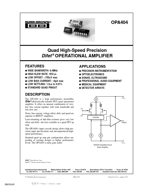
OPA404KU,OPA404KP,OPA404KU 1K,OPA404KU 1KE4,OPA404KUG4,OPA404AG,OPA404BG, 规格书,Datasheet 资料
KP, KU Operating
KP, KU Storage
KP, KU θ Junction-Ambient
KP, KU
IO = 0mADC Ambient Temperature Ambient Temperature Ambient Temperature
© 1986 Burr-Brown Corporation
PDS-677F
Printed in U.S.A. August 1995
芯天下--/
SPECIFICATIONS
ELECTRICAL
At VCC = ±15VDC and TA = +25°C unless otherwise noted.
®
OPA404
2
芯天下--/
ELECTRICAL (FULL TEMPERATURE RANGE SPECIFICATIONS)
At VCC = ±15VDC and TA = TMIN to TMAX unless otherwise noted.
OPA404AG, KP, KU
8
0.5
12
1013 || 1 1014 || 3
±10.5 88 84
+13, –11 100 100
88
100
4
6.4
570
24
35
0.6
1.5
±11.5 +13.2, –13.8
±5
±10
80
1000
±10
±27
±40
±15
±5
±18
9
10
–25
DW401A低温实验箱说明书

低温实验箱DW-40-1A使用说明书杭州蓝天化验仪器厂目录一. 仪器特点 (1)二. 技术参数 (1)三. 仪器利用…………………………………………………1-7四. 故障及排除 (8)五. 装箱单 (9)六. 合格证 (9)一.仪器特点本低温实验箱,适合医院、防疫站、血库、科研院所、高校、生物制药、基因工程、企业等需要低温贮存的场所。
箱体内贮存温度可通过操纵面板上的温度按钮调剂,利用方便,性能靠得住。
二、技术参数三、仪器利用利用前预备与注意:1.搬运:搬运时应从底部抬起,倾斜面不可大于45度,轻搬轻放。
2.切不可抓住门体或衬口作受力部件。
3.拆除所有包装组件(包括箱体内的爱惜泡沫)。
4.请按装箱单对照清点随机附件和资料。
5.利用前应付产品进行一遍打扫。
6.利用环境要求:●室内利用●安装表面必需是固定、水平、不可燃烧的和能经受低温箱工作时的重量●应放置在不受阳光直射并远离热源的地址,环境温度不高于30度●要求周围留有30cm以上的空间,便于通风散热●也不能放置在太冷能够结冰的环境中●不要放置在湿气重或易溅水的地址。
7.在平整地面上,能够直接推动低温箱进行短距离移动。
注意:关于低温实验箱箱体和地面不平常,可通过箱体前面底部两个平稳脚轮进行调剂。
注意:推动低温实验箱时,注意脚轮不要碰伤电源线。
注意:利用前必需将低温实验箱底部的包装底座取下。
注意:刚接通电源的低温实验箱不要当即放入物品,让空箱运行一段时刻后(约12小时),再将冷冻物品放入箱内贮存。
机械正常工作条件:A.环境温度:10℃~30℃B.相对湿度:≤80%C.周围无强烈震动及侵蚀性气体存在。
D.无阳光直接照射及其他冷热源的阻碍。
低温实验箱的工作制:间歇运行平安注意事项☞电源电压:该机利用220V/50HZ交流电源,若是利用电压低于198V或高于242V,需要加装适合的自动稳压器配合利用;☞必需利用单独的专用插座并进行靠得住接地,不得随意加长电源线长度,如确实需要加长,务必利用²以上铜芯导线,与电源插座相连接的墙壁内铜芯导线截面积也必需保证在4mm²以上;☞低温实验箱严禁放入易燃、易爆危险品和强侵蚀性的酸、碱等物品;☞钥匙要妥帖保管,幸免小孩拿到后开门玩耍发生意外;☞不可将插座上零线(N端)与接地线(E端)接在一路,不然将致使低温实验箱外壳带电,发生触电事故;☞电源线不要捆扎利用,不要压在家具或那么重物下面,不要切近紧缩机等热源。
海视晨光DS-2DE4A404IW-DE(2.8-12mm)4MP4×网络红外PTZ摄像头产品介绍说
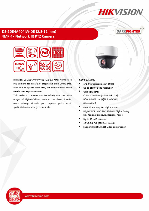
Hikvision DS-2DE4A404IW-DE (2.8-12 mm) Network IR PTZ Camera adopts 1/1.9" progressive scan CMOS chip. With the 4× optical zoom lens, the camera offers more details over expansive areas.This series of cameras can be widely used for wide ranges of high-definition, such as the rivers, forests, roads, railways, airports, ports, squares, parks, scenic spots, stations and large venues, etc.Key Features•1/1.9" progressive scan CMOS•Up to 2560 × 1440 resolution•Ultra-low light:Color: 0.002 Lux @(F1.6, AGC ON)B/W: 0.0002 Lux @(F1.6, AGC ON)0 Lux with IR•4× optical zoom, 16× digital zoom •Digital WDR, HLC, BLC, 3D DNR, Digital Defog, EIS, Regional Exposure, Regional Focus •Up to 50 m IR distance•12 VDC & PoE (802.3at, class4) •Support H.265+/H.265 video compressionCamera ModuleImage Sensor 1/1.9" progressive scan CMOSMin. Illumination Color: 0.002 Lux @(F1.6, AGC ON) B/W: 0.0002Lux @(F1.6, AGC ON) 0 Lux with IRWhite Balance Auto/Manual/ATW (Auto-tracking White Balance)/Indoor/Outdoor/FluorescentLamp/Sodium LampGain Auto/ManualShutter Time 50Hz: 1/1 s to 1/30,000 s60Hz: 1/1 s to 1/30,000 sDay & Night IR Cut FilterDigital Zoom 16×Privacy Mask 24 programmable privacy masksFocus Mode Auto/Semi-automatic/ManualWDR Digital WDRLensFocal Length 2.8 mm to 12 mm, 4× optical zoomZoom Speed Approx. 2.2 s (optical lens, wide-tele)Field of View Horizontal field of view: 69.5° to 26.48° (Wide-Tele) Vertical field of view: 38° to 14.94° (Wide-Tele) Diagonal field of view: 81.2° to 20.38° (Wide-Tele)Working Distance 10 mm to 1500 mm (wide-tele)Aperture Range F1.5 to F2.8IRIR Distance50 mSmart IR YesPTZMovement Range (Pan) 360° endlessPan Speed Configurable, from 0.1°/s to 300°/s. Preset speed: 350°/sMovement Range (Tilt) From -5° to 90° (auto-flip)Tilt Speed Configurable, from 0.1°/s to 160°/s. Preset Speed: 200°/sProportional Zoom YesPresets 300Patrol Scan 8 patrols, up to 32 presets for each patrolPattern Scan 4 pattern scans, record time over 10 minutes for each scanPower-off Memory YesPark Action Preset/Pattern Scan/Patrol Scan/Auto Scan/Tilt Scan/Random Scan/Frame Scan/Panorama Scan3D Positioning YesPTZ Position Display YesPreset Freezing YesScheduled Task Preset/Pattern Scan/Patrol Scan/Auto Scan/Tilt Scan/Random Scan/Frame Scan/Panorama Scan/Dome Reboot/Dome Adjust/Aux OutputCompression StandardVideo Compression Main Stream: H.265+/H.265/H.264+/H.264 Sub-stream: H.265/H.264/MJPEGThird Stream: H.265/H.264/MJPEGH.264 Type Baseline Profile/Main Profile/High Profile H.264+ YesH.265 Type Baseline Profile/Main Profile/High ProfileH.265+ YesVideo Bitrate 256 Kbps to 16384 KbpsAudio Compression G.711alaw/G.711ulaw/G.722.1/G.726/MP2L2/PCMSVC YesSmart FeaturesBasic Event Detection Motion Detection, Alarm Input, Alarm Output, Video Tampering, ExceptionSmart Event Detection Audio Exception Detection, Face Detection, Intrusion Detection, Line Crossing Detection, Region Entrance Detection, Region Exiting Detection, Unattended Baggage Detection, Object Removal DetectionSmart Record ANR (Automatic Network Replenishment), Dual-VCASmart Tracking Manual Tracking, Auto Tracking, Event Tracking, support multi scenes patrol tracking ROI Main stream, sub-stream, and third stream respectively support four fixed areas. ImageMax. Resolution 2560 × 1440Main Stream 50Hz: 25fps (2560 × 1440, 2048 × 1536, 1920 × 1080, 1280 × 960, 1280 × 720) 50fps (1920 × 1080, 1280 × 960, 1280 × 720)60Hz: 30fps (2560 × 1440, 2048 × 1536, 1920 × 1080, 1280 × 960, 1280 × 720) 60fps (1920 × 1080, 1280 × 960, 1280 × 720)Sub-Stream 50Hz: 25fps (704 × 576, 640 × 480, 352 × 288)60Hz: 30fps (704 × 480, 640 × 480, 352 × 240)Third Stream 50Hz: 25fps (1920 × 1080, 1280 × 960, 1280 × 720, 704 × 576, 640 × 480, 352 × 288)60Hz: 30fps (1920 × 1080, 1280 × 960, 1280 × 720, 704 × 480, 640 × 480, 352 × 240) Image Enhancement HLC/BLC/3D DNR/Digital Defog/EIS/Regional Exposure/Regional FocusNetworkNetwork Storage Built-in memory card slot, support Micro SD/SDHC/SDXC, up to 256 GB; NAS (NFS, SMB/ CIFS), ANRAlarm Linkage Alarm actions, such as Notify Surveillance Center, Upload to FTP, Send Email, TriggerRecording, Recording Linkage, and Alarm Input, etc.Protocols IPv4/IPv6, HTTP, HTTPS, 802.1x, Qos, FTP, SMTP, UPnP, SNMP, DNS, DDNS, NTP, RTSP,RTCP, RTP, TCP/IP, UDP, IGMP, ICMP, DHCP, PPPoE, BonjourAPI ONVIF (Profile S, Profile G, Profile T), ISAPI, SDKSimultaneous Live View Up to 20 channelsUser/Host Up to 32 users3 levels: Administrator, Operator and UserSecurity Measures User authentication (ID and PW), Host authentication (MAC address); HTTPS encryption;IEEE 802.1x port-based network access control; IP address filteringClient iVMS-4200, iVMS-4500, iVMS-5200, Hik-ConnectWeb Browser IE 8 to 11, Chrome 31.0+, Firefox 30.0+, Edge 16.16299+InterfaceAlarm Interface 2-ch alarm input and 2-ch alarm outputAudio Interface 1-ch audio input and 1-ch audio outputNetwork Interface 1 RJ45 10 M/100 M Ethernet, PoE (802.3at, class4)GeneralLanguage (Web Browser Access ) 32 languages.English, Russian, Estonian, Bulgarian, Hungarian, Greek, German, Italian, Czech, Slovak, French, Polish, Dutch, Portuguese, Spanish, Romanian, Danish, Swedish, Norwegian, Finnish, Croatian, Slovenian, Serbian, Turkish, Korean, Traditional Chinese, Thai, Vietnamese, Japanese, Latvian, Lithuanian, Portuguese (Brazil)Power 12 VDC, 3.33 A and PoE (802.3at), 42.5 to 57 VDC, 0.6 A, class4Max.: 18 W, including max. 5.5W for IRWorking Temperature Outdoor: -30°C to 65°C (-22°F to 149°F)Working Humidity ≤ 90%Protection Level IP66 Standard; 4000V Lightning Protection, Surge Protection and Voltage Transient ProtectionInstallation Variable installation methods optional, including ceiling mounting (default), in-ceiling mounting, pendant mounting and wall mounting Material Aluminum AlloyDimensions Φ 169 mm × 161 mm (Φ 6.65" × 6.34") WeightApprox. 2.45 kg (5.40 lb)DORIThe DORI (detect, observe, recognize, identify) distance gives the general idea of the camera ability to distinguish persons or objects within its field of view.DORI Detect Observe Recognize Identify Definition 25 px/m 63 px/m 125 px/m 250 px/m Distance (Tele)216.7 m (710.8 ft)86.0 m (282.1 ft)43.3 m (142.2 ft)21.7 m (71.1 ft)Available ModelDS-2DE4A404IW-DE (2.8-12 mm)DimensionsUnit: mm161Φ169Accessory Included:KPL-040F-VIPower adapter Optional:DS-1605ZJ Wall Mount BracketDS-1275ZJ-SUSVertical pole mountDS-1276ZJ-SUSCorner mountDS-1691ZJ-LPendant MountDS-1691ZJ-M Pendant MountDS-1691ZJPendant MountDS-1671ZJ-SD11In-ceiling Mount BracketDS-1280ZJ-SD11Junction BoxLAS60-57CN-RJ45 Hi-PoE midspanDS-1100KINetwork KeyboardDS-1005KIUSB Joy-stick05060020201109。
国产DIRIS A41说明书

仪表可直接取代常规电力变送器、测量指示仪表以及相关的辅助单元,模
块化的 结构 设计, 用户 可根 据 实 际 需 求选 择 最 为 经 济的 功 能配 置 , 具有极 高的
性能价 格比 。
仪表可广泛应用于能源管理系统、供配电网自动化、小区电力监控、成套
设备开 关柜 等场合 ,具 有安装 方便 、接线简 单 、维护方 便 ,工 程量 小、现 场可
的额定输入电压,否则应考虑使用PT,在电压输入端须安装1A 保险丝;输入
电流 应不高于产 品的额定输 入电流,否 则应考虑使 用外部CT 。
3
湘湖 DIRIS A41多功能网络电力仪表使用说明书
总 功率 有功 3 .300kW 无功0.002kv ar 视 在 3 .3 0 0 kVA
总 功率 有功 3.300 kW 无功 0.0 02k var 视在 3.3 00k VA
4
6
湘湖 DIRIS A41多功能网络电力仪表使用说明书
湘湖 DIRIS A41多功能网络电力仪表使用说明书
“显示方式”菜单 参数值/对应字符 0 循环显示
1 相电压
示例
/
相 电压 UA 220.0 V UB 22 0. 1 V UC 219 . 8 V
2 线电压
线 电压 UA B 38 0.0 V UB C 3 8 0.1 V UCA 37 9.8 V
仪 表有多种 扩展功 能模 块可供选 择 :4路模拟量( 0~2 0 mA / 4~20 mA )输出
可实现 电量 的 变送 输出 功能 ; 4路 开 关 量 输 入 和4路开 关 量 输 出 可 实 现 本地或 远
程的开 关信 号监 测 和控 制输出 功 能 ( “ 遥 信 ” 和 “ 遥 控 ” 功能 ) 。
Ra-01S规格书说明书
Ra-01S规格书版本V1.1版权©2020免责申明和版权公告本文中的信息,包括供参考的URL地址,如有变更,恕不另行通知。
文档“按现状”提供,不负任何担保责任,包括对适销性、适用于特定用途或非侵权性的任何担保,和任何提案、规格或样品在他处提到的任何担保。
本文档不负任何责任,包括使用本文档内信息产生的侵犯任何专利权行为的责任。
本文档在此未以禁止反言或其他方式授予任何知识产权使用许可,不管是明示许可还是暗示许可。
文中所得测试数据均为安信可实验室测试所得,实际结果可能略有差异。
文中提到的所有商标名称、商标和注册商标均属其各自所有者的财产,特此声明。
最终解释权归深圳市安信可科技有限公司所有。
注意由于产品版本升级或其他原因,本手册内容有可能变更。
深圳市安信可科技有限公司保留在没有任何通知或者提示的情况下对本手册的内容进行修改的权利。
本手册仅作为使用指导,深圳市安信可科技有限公司尽全力在本手册中提供准确的信息,但是深圳市安信可科技有限公司并不确保手册内容完全没有错误,本手册中的所有陈述、信息和建议也不构成任何明示或暗示的担保。
文件制定/修订/废止履历表版本日期制定/修订内容制定核准V1.02020.8.12首版徐V1.12020.8.19更新部分参数徐目录一、产品概述 (5)二、电气参数 (6)三、外观尺寸 (8)四、管脚定义 (10)五、原理图 (11)六、设计指导 (12)七、回流焊曲线图 (14)八、包装信息 (15)九、联系我们 (15)一、产品概述安信可LoRa系列模块(Ra-01S)由安信可科技设计开发。
该模组用于超长距离扩频通信,其射频芯片SX1268主要采用LoRa™远程调制解调器,用于超长距离扩频通信,抗干扰性强,能够最大限度降低电流消耗。
借助SEMTECH的LoRa™专利调制技术,SX1268具有超过-148dBm的高灵敏度,+22dBm的功率输出,传输距离远,可靠性高。
同时,相对传统调制技术,LoRa™调制技术在抗阻塞和选择方面也具有明显优势,解决了传统设计方案无法同时兼顾距离、抗干扰和功耗的问题。
DSEI60-06A;中文规格书,Datasheet资料

166 W
0.8...1.2 Nm
6
g
Symbol
IR
VF
VT0 rT RthJC RthCH trr IRM
Conditions
Characteristic Values typ. max.
VR = VRRM VR = 0.8·VRRM VR = 0.8·VRRM
TVJ = 25°C TVJ = 25°C TVJ = 125°C
IXYS reserves the right to change limits, test conditions and dimensions
© 2007 IXYS All rights reserved
/
0549
2-2
Dimensions TO-247 AD
C
D
t = 8.3 ms (60 Hz), sine
TC = 25°C mounting torque typical
Maximum Ratings
100 A 60 A
550 A 600
480 A 520Biblioteka 1510 A2s 1490
1150 A2s 1120
-55...+150 °C 150 °C
-55...+150 °C
Fast Recovery Epitaxial Diode (FRED)
DSEI60-06A DSEI60-06AT
IFAV = 60 A VRRM = 600 V trr = 35 ms
VRSM V
600 600
VRRM V
600 600
Type
DSEI 60-06A DSEI 60-06AT
A