SPDIF数据格式
视频名词解释

MIPS MIPS是世界上很流行的一种RISC处理器。
MIPS的意思是“无内部互锁流水级的微处理器”(Microprocessor without interlocked piped stages),其机制是尽量利用软件办法避免流水线中的数据相关问题。
它最早是在80年代初期由斯坦福(Stanford)大学Hennessy 教授领导的研究小组研制出来的。
MIPS公司的R系列就是在此基础上开发的RISC工业产品的微处理器。
这些系列产品为很多计算机公司采用构成各种工作站和计算机系统。
CEF自定义固件扩展功能工具Custom Firmware ExtenderTS DVD节目中的MPEG2格式,是MPEG2-PS,全称是Program Stream,TS的全称则是Transport Stream。
MPEG2-PS主要应用于存储的具有固定时长的节目,如DVD电影,而MPEG-TS则主要应用于实时传送的节目,比如实时广播的电视节目。
这两种格式的主要区别是什么呢?你将DVD上的VOB文件的前面一截剪掉(或者干脆就是数据损坏),那么就会导致整个文件无法解码,而电视节目是你任何时候打开电视机都能解码(收看)的,所以,MPEG2-TS格式的特点就是要求从视频流的任一片段开始都是可以独立解码的。
AVI英文全称为Audio Video Interleaved,即音频视频交错格式。
是将语音和影像同步组合在一起的文件格式。
它对视频文件采用了一种有损压缩方式,但压缩比较高,因此尽管面面质量不是太好,但其应用范围仍然非常广泛。
AVI支持256色和RLE压缩。
AVI信息主要应用在多媒体光盘上,用来保存电视、电影等各种影像信息。
ASI异步串行接口SMPTE—时间码概念SMPTE(The Society of Motion Picture and Television Engineers)。
它是目前在影音工业中得到广泛应用的一个时间码概念。
SPDIF接口规范详解
S P D I F接口规范详解 Document serial number【NL89WT-NY98YT-NC8CB-NNUUT-NUT108】S/PDIF接口规范详解,S/PDIF Specification(Sony/Philips Digital Interface Format)是一种数字音频传输接口,普遍使用光纤和同轴线输出,将音频信号输出值解码器上,能保持高保真度的输出结果,广泛应用在DTS(Digital Theatre System,数字化影院系统)和杜比数字中。
基本上是以AES/EBU(也称为AES3)专业用数字接口为参考然后做了一些小变动而成的家用版本,可以使用成本比较低的硬件来实现数字讯号传输。
为了定制一个统一的接口规格,在现今以IEC 60958标准规范来囊括取代AES/EBU与规范,而IEC 60958定义了三种主要型态:IEC 60958 TYPE 1 Balanced ─ 三线式传输,使用110 Ohm阻抗的线材以及XLR接头,使用于专业场合IEC 60958 TYPE 2 Unba lanced ─ 使用75 Ohm阻抗的铜轴线以及RCA接头,使用于一般家用场合IEC 60958 TYPE 2 Optical ─ 使用光纤传输以及F05光纤接头,也是使用于一般家用场合事实上,IEC 60958有时会简称为,而IEC 60958 TYPE 1即为AES/EBU(或着称为AES3)接口,而IEC 60958 TYPE 2即为接口,而虽然在IEC 60958 TYPE 2的接头规范里是使用RCA或着光纤接头,不过近年来一些使用的专业器材改用BNC接头搭配上75 Ohm的同轴线以得到比较好的传输质量,下表为AES/EBU与的比较表。
使用的编码方法在传输数据时使用双相符号编码(Biphase Mark Code),简称BMC,属于一种相位调制(phase modulation)的编码方法,是将时钟讯号和数据讯号混合在一起传输的编码方法。
浅谈数字音频接口
浅谈数字音频接口作者:Purer(1)关于数字音频接口的基本知识“数字音频接口”是用来定义两个数字音频设备之间的数字接口协议的界标准格式,它分为家用的.专业的,电脑的三种格式:①家用的标准:S/PDIF(索尼/飞利浦数字接口格式),EIAJ CP-340 IEC-958 同轴或光缆,属不平衡式。
其标准的输出电平是0.5Vpp(发送器负载75Ω),输入和输出阻抗为75Ω(0.7-3MHz频宽)。
常用的有光纤.RCA和BNC。
我们常见的是RCA插头作同轴输出,但是用RCA作同轴输出是个错误的做法,正确的做法是用BNC作同轴输出,因为BNC头的阻抗是75Ω,刚刚好适合S/PDIF的格式标准,但由于历史的原因,在一般的家用机上用的是RCA作同轴输出。
②专业的标准:AES/EBU(美国音频工程协会/欧洲广播联盟数字格式),AES3-1992,平衡XLR电缆,属平衡式结构。
输出电压是2.7Vpp(发送器负载110Ω),输入和输出阻抗为110Ω(0.1-6MHz频宽)。
③电脑的标准:AT﹠T(美国电话电报公司)。
(2)关于各种接口的优点与缺点从单纯的技术的角度来说,光纤电缆是导体传输速度最快的,是一个极好的数据传输的接线,但是由于它需要光纤发射口和接收口,问题就是出在这里,光纤发射口和接收口的光电转换需要用光电二极管,由于光纤和光电二极管不可能有紧密的接触,从而产生数字抖动(Jitter)类的失真而这个失真是叠加的,因它有两个口(发射口和接收口)。
再加上在光电转换过程中的失真,使它是几种数字电缆中最差的。
但奇怪的是日本的机十分喜欢用光纤电缆,可能生产成本比同轴便宜。
同轴电缆是欧洲机喜欢用的,凡是有数字输出的都有同轴输出。
但从我的实际上的经验发现其数字接口的重要性并不亚于光纤发射口和接收口。
同轴输入和输出的传输方法有几种:(1)用74HCU04作缓冲.放大和整形在输入和输出一样。
(2)用74HCU04作缓冲.放大和整形在输入和输出一样,但在输入和输出端加上脉冲变压器,防止数字音源通过共模噪声抑的屏蔽线输入机内,输入和输出配接脉冲变压器,内外的“地”完全隔离。
同轴和光纤输出知识
两种民用数字音频接口------光纤传输和同轴传输数字音源以数字方式处理声音讯号或数据,常见的数字音源有CD、MD、LD、DVD、DV、DAT、DCC等,根据需要,这些机器可通过数字输出、输入接口与其它的音响器材作讯号或数据的传输。
如在某些CD机上有DIGITAL OUT的端子,便于外接品质较好的DAC(数模转换器)来提升音质;而在大多数的DVD机上会同样的端子,除同样可用于外接高品质DAC外,更重要的是输出Dolby Digital 和DTS数字信号,提供给AV功放(或解码器),以获得5.1声道的环绕声音响效果。
音响器材所用的数字接口包括:数字同轴接口SPDIF(民用)、光纤接口Toshiba Link(民用)、及AES/EBU(专业)接口格式。
下面便对我们会经常接触到的民用数字接口作一简单的介绍。
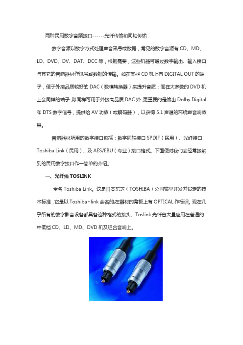
一、光纤线TOSLINK全名Toshiba Link。
这是日本东芝(TOSHIBA)公司较早开发并设定的技术标准,它是以Toshiba+link命名的,在器材的背板上有OPTICAL作标识。
现在几乎所有的数字影音设备都具备这种格式的接头。
Toslink光纤曾大量应用在普通的中低档CD、LD、MD、DVD机及组合音响上。
Toslink使用光纤传送SPDIF讯号,分两种类型,一般家用的设备都是用标准的接头,而便携式的器材如CD随身听等,则是用与耳机接头差不多大小的迷你光纤接头mini-Toslink。
光纤连接可以实现电气隔离,阻止数字噪音通过地线传输,有利于提高DAC的信噪比。
但是,时基误差是影响音质的重要因素,所以衡量数字音响设备传输接口性能的好坏,应以引起时基误差的大小为标准。
由于光纤连接的信号要经过发射器和接收器的两次转换,会产生严重影响音质的时基抖动误差(Jitter),因此这类光纤接口音质虽然较为透明,但数码味较浓,缺乏生气,显得缺乏韵味。
在市面较为常见的光纤发送器和接收器中日本品牌居多,常见的有TOSHIBA、SONY和SHARP等、它们相互间电气性能是一致的,可以通过光纤线互相连接。
音频信号传输端口介绍

各种端子介绍模拟音频端子RCA 这是目前为止最为常见的一种音/视频接线端子,这种双线连接方式的端子早在收音机出现的时代便由RCA录音公司发明出来,还有一个更老式、也比较奇怪的称呼叫作“唱盘”接头。
RCA端子采用同轴传输信号的方式,中轴用来传输信号,外沿一圈的接触层用来接地模拟音频端子RCA这是目前为止最为常见的一种音/视频接线端子,这种双线连接方式的端子早在收音机出现的时代便由RCA录音公司发明出来,还有一个更老式、也比较奇怪的称呼叫作“唱盘”接头。
RCA端子采用同轴传输信号的方式,中轴用来传输信号,外沿一圈的接触层用来接地,也可以用来传输数字音频信号和模拟视频信号。
RCA音频端子一般成对地用不同颜色标注:右声道用红色(字母“R”表示“右”或者“红色”);左声道用黑色或白色。
有的时候,中置和环绕声道连接线会用其他的颜色标注来方便接线时区分,但整个系统中所有的RCA接头在电气性能上都是一样的。
一般来讲,RCA立体声音频线都是左右声道为一组,每声道外观上是一根线。
XLR平衡端子:这是一种三线的连接端子,三根导线分别是正极、负极和屏蔽。
XLR被称作“平衡端子”和“麦克风插头”,一般来讲应用在专业或广播电视领域,但在一些Hi-End级别的消费器材中也得到采用,在前级放大器和后级放大器之间进行信号传输。
在连接方面,三线XLR插头输出音频信号,而三线插孔输入音频信号。
XLR端子的优势在于平衡线性传输信号,这样可以在长距离传送音频信号时大大减少电子系统工作时的电磁、射频干扰而在音频信号中产生的噪音和哼声。
不过呢,在一般的消费类家用电器中,XLR传输的优势并不是非常明显。
Phone/Mini-phone耳机端子标准的1/4英寸(6.35mm)直径的耳机插头和插孔的设计是从早期电话接线板来的,这种接线端子在AV器材上一般是三线结构(分为左/右声道各一以及接地),作立体声信号输出。
耳机插头与插孔通常也用于专业或广播器材上,此时是双线结构(分为信号和接地)用于传输单声道信号;有时也采用三线结构(分为正极、负极和屏蔽)以平衡方式传输单声道信号。
拆解光纤端子SPDIF信号光纤座子红色LED光感芯片参数

拆解光纤端⼦SPDIF信号光纤座⼦红⾊LED光感芯⽚参数S/PDIF,EIAJ CP1201 和 AES3 接⼝标准。
模拟部分集成插值滤波器、多 bit 数模转换器、输出模拟滤波器
光纤同轴⼯作时:低电平表⽰ SPDIF 信号是有效的 PCM 信号,复位时:⽤来设置内部数据格式,必须通过 47K 电阻下拉到地
⼯作时:采样速率检测。
如果采样速率⼩于等于 48kHz ,则输出“0”;如果采样速率⼤于等于 88.1kHz,则输出“1”。
其他情况输出未知。
复位时:通过 47K 电阻上拉或者下拉来设置数字预加重功能的开
启。
上拉时开启预加重功能,下拉时关闭预加重功能,数字预加重功能曲线见图以及数字预加重章节
S/PDIF 负向输⼊端——单端或差分接收 S/PDIF 编码的数据。
在单端信号⼯作时,该管脚应该接⼀个电容交流耦合到地。
推荐的输⼊电路
AES3,IEC60958(S/PDIF),和EIAJ CP-1201接⼝标准,接收器接收和解码双相编码⾳频数
据。
接收器由⼀个模拟差分输⼊级(驱动模拟输⼊管脚RXP0-RXP3和RXN),⼀个基于时钟恢复
的PLL电路,和⼀个⽤于把⾳频数据从通道状态和⽤户数据中分离出来的解码器。
蓝光光盘中可以使用的音频格式
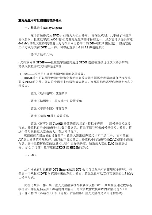
蓝光光盘中可以使用的音频格式一、杜比数字(Dolby Digital)这个音频格式从DVD开始就为人们所熟知。
并深受欢迎,几乎成了环绕声的代名词。
杜比数字(以AC-3著称)是蓝光光盘的基本标准之一。
虽然它可以提供高达640 kb/s 的最大比特率(普遍认为与在相同比特率下的DD+难以听出区别)。
但是它的工作方式与其在DVD上一样,可以配置从1.0到5.1声道的形式。
聆听方法有几种:·光纤或同轴SPDIF——杜比数字数据流通过SPDIF连接被直接送往放大器去解码,转换成模拟并放大后推动扬声器。
· HDMI——根据用户在蓝光播放机里的菜单设置。
HDMI输出可以用于传送杜比数字数据流到放大器去解码或者播放机自己执行解码成PCM的信号,并以这个形式来传送到放大器去。
在那里仍然需要作数模变换和信号放大。
蓝光《最后通牒》设置菜单蓝光《蝙蝠侠2:黑夜武士》设置菜单蓝光《变形金刚》设置菜单蓝光《急速60秒》设置菜单蓝光《迷雾》用TrueHD播放的信息显示 ·模拟多声道——用模拟信号连接方式。
播放机自身必须解码杜比数字数据流,将数字信号转换成模拟信号。
然后,将这个信号送往放大器去放大。
在这种情况下。
应该在蓝光播放机的设置菜单中置渗入渗出扬声器尺寸和声道电平。
而不是在AV放大器的菜单里选择。
最终的声音质量会由播放机中的数模转换(DAC)部件的质量与放大器中数模转换器的质量相比哪个更好来决定。
如果放大器的DAC质量更优秀。
那么宁可使用数字连接(SPDIF或HDMI)的方式。
二、DTS这个格式有时也称作DTS Encore(虽然DTS公司自己观来不再使用这个称呼)。
也是另一个从标准DVD时代遗传来的东西。
然而,蓝光光盘可以支持它更高的1.5 Mb/s 比特率形式。
同杜比数字一样,所有蓝光光盘播放机都被要求支持DTS。
其数据流通过数字连接传输,并且包括至少2声道的内部解码,而大多数播放机可以内部解码达5.1声道。
通过光纤或同轴输出Dolby、DTS到音频功放

通过光纤或同轴输出Dolby、DTS到音频功放如何设置声卡和媒体播放器,通过光纤或同轴输出Dolby、DTS到音频功放?如何通过光纤或同轴输出Dolby、DTS?Dolby、DTS和SPDIFDolby Digital(也称AC3)是Dolby实验室所发展的音频编码格式。
AC3广泛应用于5.1声道,普及度很高,以384-448 kbps的码率应用于LaserDisc和DVD,也经常以640 kbps的码率广泛用在电影院。
DTS,全称为Digital Theater Systems(数字影院系统),是一种多声道家庭影院音频格式,但它用了很高的码率进行编码,通常为768-1536kbps,DTS跟AC-3的差异处在于数据流量的大小,DTS在DVD上拥有1536Kbps的数据流量,以384Kbps~448Kbps来比较,足足多了3倍多的数据流量,即使将AC-3拉到极限的640Kbps,DTS还是强过2倍有余,这使得DTS能较AC-3听到更多的细节,整个空间感及移动感将会更加优良,更加清楚。
Dolby(AC3)和DTS数字音频信号被LD或DVD机从碟片上读取后,是如何送到声音解码、放大单元(音频功放)的呢?这就要用到SPDIF。
SPDIF(Sony Philips Digital Interface)是索尼、菲利普数字音频接口的简称,SPDIF传输的是数字信号而不是模拟信号,因此可以取得更好的抗干扰效果和很低的误码率,保证了高保真音频信号的传输。
SPDIF又分为同轴电缆和光纤两种,这又决定了它们的接口、用线的不同,但它们传输的信号是相同的。
Dolby/DTS数字音频信号经SPDIF传送到功放后,在功放内进行Dolby及DTS解码,放大输出5.1声道的声音,就能重现影院的声音效果。
如何设置播放器,电脑播放带Dolby、DTS声场的高清片源,并重现影院效果现在的很多网上片源都带有Dolby、DTS数字音频,你可以通过设置播放器分离并解码Dolby、DTS 并使用带5.1输出的电脑声卡直接输出到电脑音箱,重现影院效果,但是实际上由于电脑声卡和电脑音箱的声音还原效果较差,输出功率也比较小,在实用上价值不大,一般的做法都是用光纤或同轴将显卡的输出送到专用功放,由功放来解码并推动家庭影院音箱,所以,下面着重讲一下如何设置播放器,通过SPDIF输出Dolby、DTS数字声场到音频功放。
- 1、下载文档前请自行甄别文档内容的完整性,平台不提供额外的编辑、内容补充、找答案等附加服务。
- 2、"仅部分预览"的文档,不可在线预览部分如存在完整性等问题,可反馈申请退款(可完整预览的文档不适用该条件!)。
- 3、如文档侵犯您的权益,请联系客服反馈,我们会尽快为您处理(人工客服工作时间:9:00-18:30)。
S/PDIFFrom HwBS/PDIF = Sony/Philips Digital Interface Format (a.k.a SPDIF)An interface for digital audio.HistorySince the early 80's, a step towards digital audio has been set by the introduction of the Compact Disc player. In the beginning, those signals stayed inside the set, and were converted to analog signals before leaving the cabinet. A new trend is to keep signals into the digital domain as long as possible, because this is the only way to keep the signal quality. To make this possible different devices must be able communicate with one another within the digital domain.S/PDIF is the consumer version of AES/EBU professional digital audio interface.S/PDIF is described in IEC 60958-3:2006. In Japan the equivalent standard is JEITA CPR-1205. Characteristics IEC 60958-3 specifies up to 768 kHz sampling frequency.Contents1 History2 Characteristics3 The interface 3.1 Phono 3.2 TOSLINK 3.3 TTL level4 Comparision with AES/EBU 4.1 Multi channel audio and S/PDIF5 Quality 5.1 Jitter (clock phase noise) 5.2 Errors6 Bit rate7 The Coding Format 7.1 Word and Block Formats 7.2 Channel status and subcode information8 Electrical Interface9 Converting between AES/EBU and S/PDIF interfaces10 Jitter specifications of AES/EBU interface11 Conversion circuits12 Input/output circuits13 See also14 Links15 Standards16 Contributors 17 SourcesSignal bitrate:Resolution: up to 24 bits PCM.Audio can be sent encoded as DTS/AC-3/ATRAC/AAC/MPEG-2 instead of PCM.The interfaceThere is three different types of S/PDIF connection:Phono connector (electrical)TOSLINK connector (optical) TTLPhonoCommonly used XLR-3 microphone cables have various impedance ratings (30 Ω to 90 Ω typical) and exhibit poor digital transmission performance. The result is signal drop out and reduced cable lengths due to severe impedance mismatching (VSWR) between AES/EBU 110 Ω equipment. AES/EBU signal transmission work for few tens of meters with a good cable.TOSLINKTOSLINK = TOShiba-LINKThere also an optical version of S/PDIF interface which is usually called TOSLINK, because uses Bitrate FsUsage 2 MHz 32 kHzDSR (Digital Satellite Receiver)2.8 MHz 44.1 kHz CD3.1 MHz 48 kHz DAT S/PDIF (IEC 60958-3) Connector Phono TOSLINKNon-standard Interface Unbalanced OpticalUnbalanced Cabling 75 Ω coaxial 1.0 mm plastic fiber optics ?Max length10 m 1 m ? m Output level0.5 V pp ? 5 V pp (TTL) Max output0.6 V pp ? 5 V pp (TTL) Max current8 mA ? X mA Min input 0.2 V pp ? 2 V pp (TTL) Modulation biphase-mark-codeSubcode information SCMS copy protection infoMax. Resolution 20 bits (24 bit optional)TOSLINK optical components. The transmission media is 1 mm plastic fiber and the signals are transmitted using visible light (red transmitting LED). The optical signals have exactly the same format as the electrical S/PDIF signals, they are just converted to light signals (light on/off). Because high light signal attenuation in the TOSLINK fiber optic cable, the transmission distance available using this technique is less than 10 meters (with some equipments only few meters).Connector is called JIS F05 (JIS C5974-1993 F05)TTL levelThe 2 pin header connection found on CD-ROM units and sound cards (internally) are usually TTL level. The data format is same as the other formats. You need an adapter to connect the TTL level signal to an amplifier with Phono or TOSLINK connectors.Comparision with AES/EBUThe two formats are quite compatible with each other, differing only in the subcode information and connector. The professional format subcode contains ASCII strings for source and destination identification, whereas the commercial format carries the SCMS.Both S/PDIF and AES/EBU can, and do transfer 24 bit words. In AES/EBU, the last 4 bits have a defined usage, so if anyone puts audio in there, it has to go to something that doesn't expect the standard specifies. But in S/PDIF, there's nothing that says what you have to use the bits for, so filling them all up with audio is acceptable. Typical S/PDIF equipments only use 16 or 20 bit resolutions. While many equipments use more than 16 bits in internal processing, it's not unusual for the output to be limited to 16 bits.Multi channel audio and S/PDIFIEC 958 was named IEC 60958 in 1998. IEC 60958 (The S/PDIF) can carry normal audio and IEC 61937 data streams. IEC 61937 data streams can contain multi channel sound like MPEG2, AC3 or DTS. When IEC 61937 data streams are transferred, the bits which normally carry audio samples are replaced with the data bits from the data stream and the headers of the S/PDIF signal. Channel-status information contains one bit (but 1) which tells if the data in S/PDIF frame is digital audio or some other data (DTS, AC3, MPEG audio etc.).This bit will tell normal digital audio equipments that they don't try to play back this data as they were audio samples. (would sound really horrible if this happens for some reason).The equipments which can handle both normal audio and IEC 61937 just look at those header bits to determine what to do with the received data.QualityThere are two things which can cause differences between the sound of digital interfaces:Jitter (clock phase noise)This really only affects sound of the signal going directly to a DAC. If you're running into a computer, the computer is effectively going to be reclocking everything. Same applies also to CD-recorders, DAT tape decks and similar devices. Even modern DACs have typically a small bufferand reclocking circuitry, so the jitter is not so big problem nowadays that it used to be.ErrorsThis usually causes very significant changes in the sound, often loud popping noises but occasionally less offensive effects. Any data loss or errors in either are a sign of a very broken link which is probably intermittently dropping out altogether.Bit rateThe signal on the digital output of a CD-player looks like almost perfect sine-wave, with an amplitude of 500 mVtt and a frequency of almost 3 MHz.For each sample, two 32-bit words are transmitted, which results in a bit-rate of:2.8224 Mbit/s 44.1 kHz sampling rate, CD, DAT3.0720 Mbit/s 48 kHz sampling rate, DAT2.0480 Mbit/s 32 kHz sampling rate, for satellite purposesThe Coding FormatThe digital signal is coded using the 'biphase-mark-code' (BMC), which is a kind of phase-modulation. In this system, two zero-crossings of the signal mean a logical 1 and one zero-crossing means a logical 0.The frequency of the clock if twice the bitrate. Every bit of the original data is represented as two logical states, which, together, form a cell. The length of a cel ('time-slot') is equal to the length of a databit. The logical level at the start of a bit is always inverted to the level at the end of the previous bit. The level at the end of a bit is equal (a 0 transmitted) or inverted (a 1 transmitted) to the start of that bit.The first 4 bits of a 32-bit word (bits 0 through 3) form a preamble which takes care of synchronisation. This sync-pattern doesn't actually carry any data, but only equals four data bits in length. It also doesn't use the BMC, so bit patterns which include more than two 0's or 1's in a row can occur (in fact, they always do).There are 3 different sync-patterns, but they can appear in different forms, depending on the last cell of the previous 32-bit word (parity):cell-order cell-orderWord and Block FormatsEvery sample is transmitted as a 32-bit word (subframe). These bits are used as follows:The number of subframes that are used depends on the number of channels that is transmitted. A CD-player uses Channels A and B (left/right) and so each frame contains two subframes. A block contains 192 frames and starts with a preamble "B":Channel status and subcode informationIn each block, 384 bits of channel status and subcode info are transmitted. The Channel-status bits are equal for both subframes, so actually only 192 useful bits are transmitted: Preamble (last cell "0") (last cell "1")"B" 11101000 00010111"M" 11100010 00011101"W" 11100100 00011011Preamble B Marks a word containing data for channel A (left) at the start of the data-block.Preamble M Marks a word with data for channel A that isn't at the start of the data-block.Preamble W Marks a word containing data for channel B. (right, for stereo).When using more than 2 channels, this could also be any other channel (except for A). bits meaning 0-3 Preamble (see above; special structure)4-7 Auxillary-audio-databits8-27 Sample(A 24-bit sample can be used (using bits 4-27).A CD-player uses only 16 bits, so only bits 13 (LSB) to 27 (MSB) are used. Bits 4-12 are set to 0).28 Validity(When this bit is set, the sample should not be used by the receiver. A CD-player uses the 'error-flag' to set this bit).29 Subcode-data30 Channel-status-information31Parity (bit 0-3 are not included)"M" Ch.1 "W" Ch.2 "B" Ch.1 "W" Ch.2 "M" Ch.1 "W" Ch.2 "M" ...sub subFrame 191 Frame 0Frame 1Block startThe subcode-bits can be used by the manufacturer at will. They are used in blocks of 1176 bits before which a sync-word of 16 "0"-bits is transmittedElectrical InterfaceThe electrical interface for S/PDIF signals can be either 75 Ω coaxial cable or optical fiber (usually called TOSLINK). Usually consumer models use that coaxial cable interface andsemiprofessional/professional equipments use optical interface. The electrical signal in the coaxial cable is about 500mVtt.Converting between AES/EBU and S/PDIF interfacesThere are differences in the electrical characteristics of AES/EBU and S/PDIF interfaces:AES/EBU uses a balanced differential line based on XLR connectors and the signal levels are 5 volts S/PDIF uses a coaxial unbalanced line with RCA connectors and the signal levels are around 0.5 voltsYou can convert one electrical interface to another with a small amount of off-the-shelf hardware and a little time as you can see in the circuit below.But the protocol used in AES/EBU and S/PDIF is not exactly the same and that can cause sometimes problems. The basic data format of AES and S/PDIF are identical. There is a bit in the channel status frame that tells which is which. Depending upon the setting of that bit, some bits have different meanings. For example, the bits used to describe de-emphasis in the AES/EBU protocol overlap the bits used to implement the SCMS protocol in S/PDIF land. bit meaning 0-1 channel status bits:bit 0 bit 10 0 IEC 60958-3 (Consumer)1 0 IEC 60958-4 (Professional)1 IEC 61397 (MPEG/AC-3/DTS/AAC/ATRAC), IEC 62105 and others 1 1 SMPTE 337M and others2copy-protection. Copying is allowed when this bit is set. 3 is set when pre-emphasis is used.4-7 0 (reserved)9-15 category-code:0 = common 2-channel format1 = 2-channel CD-format (set by a CD-player when a subcode is transmitted)2 = 2-channel PCM-encoder-decoder format others are not used19-191 0 (reserved)Some equipment are very flexible and will reject data that is different from what it is expecting. So an S/PDIF equipment may reject AES/EBU data.Jitter specifications of AES/EBU interfaceThe AES/EBU standard for serial digital audio uses typically 163 ns clock rate and allows up to -20 ns of jitter in the signal. This peaks to peak value of 40 ns is aroun 1/4 of the unit interval. D/A conversion clock jitter requirements are considerably tighter. A draft AES/EBU standard specifies the D/A converter clock at 1 ns jitter; however, a theoretical value for 16-bit audio could be as small as 0.1 nsec. Small jitter D/A conversion is implemented by using separate PLL clocks for data recover and DAC and by using a buffering between data recovery and DAC.Conversion circuitsRemember that although the audio data is the same in both AES/EBU and S/PDIF interfaces, they are indeed different formats, at least in their subcode. AES converted to coax is NOT S/PDIF, and S/PDIF converted to XLR balanced is NOT AES. They are still their native format, just the transmission medium has changed. Whether they will work in your application depends on the equipment chosen.Some DATs have a switch that selects one format or the other regardless of the physical interface, some just ignore what they don't understand (usually resulting in the generally positive benefit of ignoring SCMS encoding), and some indeed gag on the "other" format. But simply fixing the physical interface works far more often than it doesn't.Adapters between different formats:AES3 to AES3idAES3 to S/PDIFAES3id to AES3AES3id to S/PDIFS/PDIF to AES3Input/output circuitsS/PDIF inputS/PDIF outputS/PDIF opticalSee alsoAES/EBULinksThe EBU/AES Digital Audio Interface: Engineering Guidelines(http://www.ebu.ch/CMSimages/en/tec_AES-EBU_eg_tcm6-11890.pdf) StandardsIEC 60958-3:2006 (old name: IEC 958-3:1989)JEITA CPR-1205 (former EIAJ CP-340 1987-9 & EIAJ CP-1201)(CP-1201 Japanese equivalent of IEC 60958)ContributorsJoakim ÖgrenSourcesThis page is based on : S/PDIF(/documents/audio/spdif.html) by Tomi Engdahl (2002-05-28).Page published with permission from author.Usenet posting(/group/tw.bbs.rec.audiophile/msg/82ba735776111364?dmode=source) by Fred Peng in tw.bbs.rec.audiophileRetrieved from "/S/PDIF"Category: Information。