A FAULT DETECTION SENSOR FOR CIRCUIT AGING USING DOUBLE-EDGE-TRIGGERED FLIP-FLOP
江苏省苏州市2024-2025学年高二上学期11月期中英语试题
江苏省苏州市2024-2025学年高二上学期11月期中英语试题一、阅读理解When you volunteer through United Way, you’ re joining 1.5 million people who are giving back so others can get ahead. Use your time and talent to create social change where you work or live — join our community of game changers.If you are accepted to become a United Way volunteer, you will be required to complete the series of immunization (免疫) requirements listed below. It is requested that you complete all of your immunization requirements through your own healthcare provider. However, if this presents a financial hardship for you, Employee Health or Occupational Health may be able to assist with these requirements.V olunteer duties vary, but may include visiting and socializing with patients, helping withlight tasks such as sorting or filing, and assisting patients/visitors with wayfinding.V olunteers cannot perform any “hand-on” or clinical duties, perform the same job as staff members, or shadow or observe medical staff.We do not offer any research or internship opportunities.1.What is the purpose of the United Way?A.To inform volunteers to take the vaccines.B.To attract volunteers to make a difference.C.To create social change in the community.D.To provide an opportunity of internship. 2.What can be learned about immunization requirements?A.Two doses of MMR are necessary for Measles.B.TDaP should be shot at the age of 17 immediately.C.2 negative TB tests are given in prior 12 months.D.Hepatitis B Vaccine is only for regional volunteers.3.What are the volunteers expected to do?A.Assist dying patients file their wills.B.Direct the way for patients and visitors.C.Take medical workers’ place in case.D.Observe doctors in a clinical setting.In 2015, Brian Peterson, a car designer for Kia Motors, moved to Santa Ana, California, with his wife, Vanessa. There, they often met a homeless man named Matt Faris, who would frequently shout on the street corner, sometimes disturbing their sleep. Initially, Peterson had no interaction with Faris, but everything changed after reading the book Love Does, which stressed the power of love in action. Inspired by the book, Peterson decided to introduce himself to Faris.In their first conversation, Peterson learned that Faris had moved to Southern California from Kentucky in pursuit of a music career but had fallen on hard times, living on the streets for over a decade. Despite Faris’s rough appearance, Peterson saw beauty in him and felt forced to paint his portrait, even though he hadn’t picked up a paintbrush in eight years. Faris agreed, marking the start of a transformative project.So Peterson went to establish Faces of Santa Ana, a nonprofit organization dedicated to painting portraits of unhoused individuals in the community. He captures each subject’s personality through colors and then sells the portraits, splitting the earnings with the subject. Half of the funds are placed in a “love account”, which helps them to address their personal needs.However, Peterson learned the importance of asking people directly how they wanted to use the money rather than assuming what they need most. For example, Faris used the funds from his portrait to record an album, while another subject, Kimberly Sondoval, used the money to help pay her daughter’s rent.Over the years, Peterson’s project expanded, leading him to found Faces of Mankind, where artists nationwide paint portraits of the homeless. To date, Peterson has personally painted 41 portraits. His work not only provides financial assistance but also fosters understanding and connection between the buyers and the subjects, with many buyers developing friendships with the individuals they initially overlooked. Peterson hopes his work will continue to change how people perceive the homeless.4.What inspired Brian Peterson to approach Matt Faris?A.He saw Faris had artistic talent.B.He read a book about love in action.C.He wanted to complain about Faris’s shouting.D.He intended to found a nonprofitorganization.5.How does Brian Peterson deal with the money he earns from selling the portraits?A.He donates it to charities.B.He uses it to expand his project.C.He sponsors the homeless to buy art supplies.D.He keeps half and gives the other half to his subjects.6.What is true about Peterson in Paragraph 3?A.He believes in giving without accepting.B.He prefers to decide how the money should be spent.C.He helps people based on their personal needs.D.He funds them to develop art-related projects.7.What would be the best title for this passage?A.Painting for Homeless B.Art Can Cure HomelessnessC.The Story of Matt Faris D.Selling Portraits for CharityScientists from the Hefei Institutes of Physical Science (HIPS) under the Chinese Academy of Sciences have designed a wristwatch that can measure essential chemicals in body sweat. Theirfindings were published in the journal ACS Nano.Sweat contains electrolytes (电解质), primarily potassium, sodium and calcium. The balance of these essential minerals is crucial for supporting muscle function, nerve health and regular heartbeat. The wristwatch collects sweat from the skin and analyzes it in real time using a sensor chip with sensitive membrane. When sweat enters the device, it will come into contact with the membrane that contains three tubes capable of measuring sodium, potassium and calcium levels respectively.Although they are not the first to invent sweat sensors, the Chinese researchers emphasized the wrist watch’s solid interface for long-term reliability. “It surpasses the stability of many other sensors by consistently monitoring human sweat for over six months,” said the lead researcher Huang Xingjiu.Since athletes use electrolyte drinks to counteract (抵制) the loss of energy and refill it, researchers in the study measured the sweat composition of these chemicals in athletes running long distances. The accuracy reached about 95 percent when compared to the standard detection method.“When there are electrolyte abnormalities, the device will remind users to supplement (补充) them quickly. The aim of developing this device is to provide warnings for electrolyte loss and reduce exercise-related injury risks.”For ordinary people, the traditional electrolyte test requires samples of body fluids taken in hospitals. The new wristwatch has the potential to serve as an alternative to needles for measuring electrolytes.The next goal of the research team is to design various sensitive membrane materials for monitoring more information. The researchers noted that compared to popular fitness watches on the market, the device they designed is larger and heavier, making it less comfortable to wear. However, they expect to develop wearable sweat sensors suitable for market applications in the next five years. The team of researchers also aims to adapt the device for environmental monitoring.8.What is Paragraph 2 mainly about?A.The working principle of the device.B.The composition of sweat.C.The function of a particular sensor.D.The balance of the minerals.9.Which of the following is the advantage of the wristwatch?A.accurate and popular.B.large and wearable.C.convenient and comfortable.D.reliable and stable.10.What does the author imply in the last paragraph?A.The wristwatch has no equal now.B.The product hasn’t hit the market yet.C.The researchers are content with the product.D.The device will be definitely put into extensive use.11.What is the purpose of the passage?A.To provide warnings for readers to reduce risks.B.To introduce a new product on monitoring health.C.To inform the readers of the importance of eletrolytes.D.To analyze the relationship between sweat and health.Victories are temporary in China’s fast-changing economy. Earlier this month Colin Huang, the founder of Pinduoduo, became China’s richest man. The company, founded in 2015, today is China’s third-largest e-commerce firm by sales, behind only JD.com and Alibaba.Mr Huang’s time atop China’s rich list was, however, brief. On August 26th Pinduoduo’s share price decreased by nearly 30% after it reported sales for the quarter from April to June fell short of the market’s high expectations and gave warning that a long-run decline in profitability was “unavoidable”.Pinduoduo’s misfortunes are set against a backdrop of weakening consumer spending in China. In June sales from the “618” shopping festival fell for the first time, despite a number of platforms extending their sales periods this year. A fierce price war is adding to the trouble. Visit any Chinese e-commerce site and you will be impressed by signs advertising huge discounts and promising the cheapest deals online. Competition has grown more intense because of attacks into e-commerce by short-video apps such as Douyin and Xiaohongshu. Some merchants are piling yet more pressure on the industry. Some Chinese e-commerce companies juice their sales by fining merchants for late deliveries or product mismatches. Last month hundreds of suppliers surrounded the offices of Temu, Pinduoduo’s foreign branch, in the southern city of Guangzhou to protest against such punishment.Pinduoduo may be hoping that international expansion will rescue it from deteriorating conditions at home. That will not be straightforward. Although the number of people using Temu, which launched in America in 2022, has rocketed, owing in no small part to the vast amounts it has spent on advertising, turning that into profit has proved trickier.What is more, America’s e-commerce Amazon is fighting back against the Chinese upstart. During its Prime Day sale in July it offered discounts of up to 70% on some products. It is also reportedly planning to launch a discount section on its site which will feature cheap items. 12.Why did Pinduoduo’s share price decrease sharply?A.China is experiencing a major economic boom.B.Colin Huang failed to run the company well.C.Sales for the second quarter didn’t meet the expectations.D.Consumers were unwilling to spend money on the platform.13.What difficulty is Pinduoduo faced with?A.The rapid rise of JD.com and Alibaba.B.The pressure from consumers and suppliers.C.The invasion of many overseas e-commerce giants.D.The intense price competition and weak purchasing power.14.What does the underlined word “deteriorating” in paragraph 4 probably mean?A.Declining.B.Alarming.C.Increasing.D.Changing. 15.How does the author find Pinduoduo’s expansion of international market?A.Hopeful.B.Cautious.C.Unclear.D.Favourable.People are constantly bombarded (轰炸) with unrealistic and potentially harmful images of “ideal” body types. 16 It’s also important to learn what your body can physically do and become comfortable. In order to accept your body, it’s important to get in touch with both of these aspects of your body on their own terms.17 This means not trying to change who you are or focus on qualities you don’t like. Learn to enjoy your body —— how you move, feel, and get around. Let go of how you used to look, especially if your body has undergone changes from injuries, or medical conditions. Be kind to your body as it is right now.Replace negative thoughts with positive ones. As soon as you notice yourself starting to have a negative thought, replace it with something positive about yourself. Give yourself time to get into the habit of thinking positively. Try starting each day by thinking a few positive thoughts.18Compare yourself only to yourself. 19 There’s no point in comparing yourself to others, regardless of whether the person is a celebrity or classmate sitting next to you. Instead, compare yourself in terms of how you’ ve progressed over time, now that you’ve created your own realistic goals. For example, you might think to yourself that you’ve improved your appearance compared to a few years ago.Know when to seek help. Understand that nearly everyone struggles to maintain positive body image all the time and it’s normal to have ups and downs. 20 There are various signs that your body issues are severe and require professional help.A.Accept your body as it is.B.Identify what you like about your body and appearance.C.Negative thoughts do nothing to improve your self-image.D.The world would be a pretty boring place if we all looked the same.E.But you should also honestly consider if you need to speak with a counselor, or specialist. F.This can make it difficult to accept, love, and feel confident in your own body, which is critical. G.Remind yourself of these thoughts throughout the day when you start feeling critical of yourself.二、完形填空Ever since I was little, the doctors told my parents that someday I would need hearing aids. Of all my 21 my ears are the ones I hate the most. Although my hearing was getting22 I hadn’t told anyone. The ocean sound that was always in my head had been getting louder,23 people’s voices, I even couldn’t hear teachers in class. But I knew if I told Mom about it, I’d 24 hearing aids.Then in my annual checkup, I 25 the audiology test and the doctor said, “Dude, it’s time.” And he 26 me to a special ear doctor. When the ear doctor first pulled thehearing aids out for me, I groaned.Normal aids usually have a part that wraps around the outer ear to hold the inner bud 27 . But since I didn’t have outer ears, they had to put the earbuds on this heavy-duty headband to wrap around the back of my 28 . I could imagine how strange I’d look — my classmates would laugh at me, and even my teachers, my friends would be 29 at me!“Can’t wear that, Mom; I’ll look like Lobot!” I complained.“Lobot?” The ear doctor smiled as he looked at the headphones and made some 30 . “The Empire Strikes Back? The bald guy?”“You know Star Wars stuff?” I asked. “Hey, Lobot’s cool,” said he, 31 the earphones on my head carefully. “There you go. So how’s that?”“It’s so quiet in my ears and I don’t hear that noise anymore! Thanks so much, Dr. James!”I answered 32 .The first day I showed up at school with the hearing aids, I thought kids would make a big 33 about it. But no one did. Now that I look back, I don’t know why I was so 34 about it all this time. Funny how sometimes you worry a lot about something and it turns out to be 35 .21.A.favorites B.features C.figures D.frights 22.A.worse B.less C.sharper D.lower 23.A.giving out B.making out C.bringing out D.drowning out 24.A.end up with B.keep up with C.put up with D.break up with 25.A.had B.failed C.escaped D.passed 26.A.invited B.brought C.sent D.showed 27.A.in place B.in order C.in use D.in store 28.A.ears B.head C.back D.chest 29.A.surprised B.amazed C.scared D.annoyed 30.A.differences B.efforts C.comments D.adjustments 31.A.hanging B.sliding C.striking D.arranging 32.A.automatically B.loudly C.greedily D.excitedly 33.A.fortune B.choice C.deal D.decision 34.A.stressed B.curious C.mad D.disappointed35.A.something B.everything C.anything D.nothing三、语法填空阅读下面短文,在空白处填入1个适当的单词或括号内单词的正确形式Breakdancing (霹雳舞) made its debut as an Olympic sport after 36 ( include) in this year’s games in Paris. It was the only new event 37 broke into the Olympics at this year’s games.38 (begin) in the Bronx in the 1970s and popularized globally through media, breaking has faced skepticism about its classification 39 a sport. The term “breakdancing” was coined by journalists 40 is not used by supporters. Indeed breakers never seriously 41 ( seek) a place at the games. They were generally 42 ( interest) in gold chains than gold medals. Thanks to the World Dance Sport Federation, breaking’s inclusion aimed to attract younger viewers and refresh Olympic viewership, highlighting both challenges and opportunities for its 43 ( participate).The flips (翻转) and 44 ( freeze) may be short-lived, however. Breaking will not return in Los Angeles in 2028. The IOC’s charter (章程) caps the number of athletes at 10,500 and host cities have 45 final say over their games. Organizers in LA chose to include larger and better-funded sports such as baseball and cricket.四、单词拼写46.Her sharp (辨别力) in artworks allowed her to distinguish genuine pieces and clever reproductions. (根据汉语提示单词拼写)47.A fortunate (相遇) on the street brought the two friends together after a long separation. (根据汉语提示单词拼写)48.We can provide you with a (全面的) guide to local hotels and restaurants. (根据汉语提示单词拼写)49.The (零花钱) her parents gave her each month taught the young student the value of saving and budgeting responsibly. (根据汉语提示单词拼写)50.Smartphones should be used as our tools rather than (主宰) our lives. (根据汉语提示单词拼写)51.R could I find a book that I was deeply absorbed in. (根据首字母单词拼写) 52.The government is c to reducing poverty and has made remarkable progress. (根据首字母单词拼写)53.The bomb exploded during the night, t lots of people in the building. (根据首字母单词拼写)54.The sudden news of his death s her suddenly, leaving her stunned and unable to react. (根据首字母单词拼写)55.The report presented a f account of the events that took place, without any exaggeration. (根据首字母单词拼写)五、书信写作56.假如你是李华,你校将给美国的友好学校赠送一批具有中国特色的学生书画作品,请你代表学校给该校校长Mr. Thomson写一封信,内容要点如下:1. 赠书画作品的目的;2. 简要介绍其中一幅书画;3. 表示需要与其沟通捐赠细节。
施耐德断路器和熔断器的比较

Data Bulletin0600DB06012/2007 Cedar Rapids, IA, USAA Comparison of Circuit Breakers and Fuses forLow-Voltage ApplicationsTony Parsons, PhD, P.E.,Square D / Schneider Electric Power Systems EngineeringI. Introduction Recent claims by fuse manufacturers regarding the arc-flash and simplified-coordination benefits of fuses do not tell the entire story regarding whichtype of device is “best” for a given power system. In reality, not only doesthe wide range of available circuit breaker types allow them to besuccessfully used on nearly any kind of power system, they can be appliedso as to provide selective coordination, arc-flash protection, advancedmonitoring and control features, all in a renewable device. This paper givesa feature-by-feature comparison of the merits of circuit breakers vs. fuses,discussing the relative merits of fuses and circuit breakers in each section.While both circuit breakers and fuses are available for application insystems that operate at higher voltage levels, the focus of this guide is onlow-voltage systems operating at 600 V or below.II. Basic Definitions and Requirements Article 240 of the National Electrical Code® (NEC) [1] provides the basic requirements for overcurrent (i.e., overload, short-circuit, and/or ground fault) protection in a power system. Special requirements for overcurrent protection of certain types of equipment are also contained in other articles—for example, details on protection requirements for motors and motor circuits are given in Article 430, while transformer protection requirements are given in Article 450.The NEC defines the two basic types of Overcurrent Protective Devices (OCPDs):fuse—An overcurrent protective device with a circuit-opening fusible part that is heated and severed by the passage of overcurrent through it.circuit breaker—A device designed to open and close a circuit bynonautomatic means and to open the circuit automatically on apredetermined overcurrent without damage to itself when properlyapplied within its rating.The NEC also requires that circuits be provided with a disconnecting means, defined as “a device, or group of devices, or other means by which the conductors of a circuit can be disconnected from their source of supply.” Since fuses are designed to open only when subjected to an overcurrent, they generally are applied in conjunction with a separate disconnecting means (NEC 240.40 requires this in many situations), typically some form of a disconnect switch. Since circuit breakers are designed to open and close under manual operation as well as in response to an overcurrent, a separate disconnecting means is not required.Both fuses and circuit breakers are available in a variety of sizes, ratings, and with differing features and characteristics that allow the designer of an electrical system to choose a device that is appropriate for the system under consideration.Data Bulletin2/2007Low-voltage fuses are available in sizes from fractions of an amp tothousands of amps, at voltage ratings up to 600 V, and with short-circuitinterrupting ratings of 200 kA or more. Fuses are inherently single-poledevices (i.e., an individual fuse can only operate to open one phase of amulti-phase circuit), but two or three individual fuses can be applied togetherin a disconnect to protect a multi-phase system. Low-voltage fuses aretested and rated according to the UL 248 series of standards. Several typescan be classified as current-limiting, which per the NEC definition meansthat they “...reduce the current flowing in the faulted circuit to a magnitudesubstantially less than that obtainable in the same circuit if the device werereplaced with a solid conductor having comparable impedance.” In otherwords, the current-limiting fuses open very quickly (within 1/2 cycle) in thepresence of a high-level fault, allowing them to provide excellent protectionfor distribution system components or load equipment. Fuses can beapplied in equipment such as panelboards, switchboards, motor controlcenters (MCCs), disconnect switches/safety switches, equipment controlpanels, etc.Circuit breakers are also available with a wide range of ratings—10 A tothousands of amps, also with short-circuit interrupting ratings to 200 kA—and are available as 1, 2, 3, or 4-pole devices. The three basic types of LVcircuit breakers are the molded-case circuit breaker (MCCB), low-voltagepower circuit breaker (LVPCB), and insulated-case circuit breaker (ICCB).MCCBs are rated per UL 489, have all internal parts completely enclosed ina molded case of insulating material that is not designed to be opened(which means that the circuit breaker is not field maintainable), and can beapplied in panelboards, switchboards, MCCs, equipment control panels,and as stand-alone disconnects inside a separate enclosure. LVPCBs,which are rated per ANSI standards and are applied in low-voltage drawoutswitchgear, are larger, more rugged devices that may be designed to befully field maintainable. ICCBs can be thought of as a “cross” betweenMCCBs and LVPCBs—they are tested per UL 489 but may share somecharacteristics with LVPCBs, including two-step stored energy mechanismavailability in drawout construction and partial field maintainability [2].Both types of OCPDs can meet the basic requirements of the NEC, but arecircuit breakers or fuses best suited for a particular application?Unfortunately, there is no simple answer to this question—several otherfactors must be taken into account, such as the level of protection providedby the OCPD, selective coordination requirements, reliability, renewability,and flexibility. The remainder of this guide will provide a discussion of eachof these topics.III. System Protection As discussed above, both circuit breakers and fuses meet the basic NECrequirements for overcurrent protection of electric power distributionsystems and equipment. Any type of OCPD must be sized and installedcorrectly after taking all derating factors and other considerations intoaccount. Particularly for overloads and phase faults, both circuit breakersand fuses provide excellent protection and either is suitable for mostapplications. A bit more consideration is warranted for some other aspectsof system protection, as discussed in the remainder of this section.A. Ground-Fault Protection Conventional wisdom states that the most common type of fault in a powersystem (by far) is a single-phase-to-ground fault. On solidly-grounded powersystems, the available ground-fault current level can be significant. In somesituations, ground fault current levels that are even higher than themaximum three-phase fault current level are theoretically possible.However, many ground faults produce only relatively low levels of faultcurrent due to impedance in the fault path (due to arcing or to some other2/2007Data Bulletinsource of impedance from phase to ground). While such faults can causesignificant equipment and facility damage if not cleared from the systemquickly, phase overcurrent protective devices may not respond quickly tothe lower fault levels—if they detect the fault at all. For example, an 800 Aground fault might simply appear as an unbalanced load to a 4000 A fuse orcircuit breaker not equipped with ground-fault protection. Because of this,NEC 230.95 requires supplementary ground-fault protection on servicedisconnects rated 1000 A or more on solidly-grounded, wye systemsoperating at more than 150 V to ground but not more than 600 V phase-to-phase (e.g., 277/480 V systems). The NEC also defines special ground-faultprotection requirements for health care facilities and emergency systems.See the appropriate NEC articles for more details.Circuit breakers can be equipped with integral ground-fault protectionthrough addition of either electronic trip units that act as protective relayingto detect the ground fault and initiate a trip, or through addition of add-onground-fault protection modules. Ground-fault trip units typically use thecurrent sensors internal to the circuit breaker to detect the ground faultcondition, though an external neutral sensor is normally required to monitorcurrent flowing on the neutral conductor in a 4-wire system. If desired,external relaying and current transformers (CTs) can also be used forground-fault detection provided that the circuit breaker is equipped with ashunt trip accessory that can be actuated by the external relay.By themselves, fuses cannot provide ground-fault protection except forrelatively high-level ground faults. When ground-fault protection is requiredin a fusible system, the disconnecting means (usually a switch, sometimes acontactor) must be capable of tripping automatically, and external relayingand a zero-sequence CT or set of residually-connected phase CTs must beinstalled to detect the ground faults and send the trip signal to thedisconnecting means.While either system can function well if installed properly, extra care mustbe taken with a fusible system (or circuit breaker-based system withexternal ground relaying) to ensure that all external sensors are orientedcorrectly and that all sensor and relay wiring is installed correctly.Performance testing of the ground-fault system, as required in NEC230.95(C) when the system is installed, should allow for identification of anyinstallation issues.B. Device Interrupting Ratings NEC 110.9 states that “equipment intended to interrupt current at faultlevels shall have an interrupting rating sufficient for the nominal circuitvoltage and the current that is available at the line terminals of theequipment.” Protective devices that are inadequately rated for either thesystem voltage or available fault current levels present a safety hazard, asthere is no guarantee that they will be able to interrupt faults withoutdamage either to themselves or to other equipment in the system. Thiscould result in extended downtime and present a significant fire hazard.Several types of low-voltage fuses (class R, class J, etc.) carry interruptingratings of 200 kA or more at up to 600 V. This is typically high enough tointerrupt even the most severe fault in the “stiffest” system. In addition, sincefuses are single-pole devices, their single-pole interrupting capability equalsthe full rating of the fuse. Note that the withstand rating of the equipment(e.g., panelboards, switchboards) in which fuses are applied may notalways be equal to the ratings of the fuses themselves—equipmentmanufacturers should be consulted, particularly when system fault currentsexceed 100 kA. Note also that some LV fuses have interrupting ratings aslow as 10 kA, so care should always be taken to ensure that fuses selectedare appropriate for the installation.Data Bulletin2/2007Circuit breakers of all types are also available with interrupting ratings up to200 kA. In the not-too-distant past, fused circuit breakers were required toachieve the 200 kA interrupting ratings, but modern circuit breakers canachieve this rating without fuses. Circuit breakers with lower ratings are alsoavailable, typically at a lower cost. Circuit breakers have single-poleinterrupting ratings that are adequate for installation on the majority of powersystems, though special consideration may be required in some cases. See[3] for additional information.C. Motor Protection Overcurrent Protective Devices (OCPDs) in motor circuits have a relativelydifficult job to perform. They must not trip on motor inrush current, but shouldbe sensitive enough to provide both overload protection and short-circuitprotection to the motor and its associated branch circuit. In many cases, thefuse/circuit breaker (or motor circuit protector—MCP which is essentially amolded-case circuit breaker with no overload element), is oversized toaccommodate motor inrush current and a separate overload relay is addedthat will open the motor contactor during overload conditions. These twodevices then combine to provide overload and short-circuit protection for themotor circuit.Motors can also be damaged by conditions other than short-circuits andoverloads. On three-phase systems, one of the most problematic abnormalconditions is system voltage unbalance, which can cause an increase inphase currents and create high negative-sequence currents that flow in themotor windings. Both of these cause increased heating in the motorwindings, which can cause insulation degradation or breakdown that canultimately result in failure of the motor. Unbalance from system sources suchas unbalanced load in a facility or voltage unbalance on the utility system ispotentially problematic whether circuit breakers or fuses are used as motorOCPDs. However, the use of fuses has the potential to produce a severeunbalance condition commonly referred to as single-phasing.Single-phasing occurs when one phase in a three-phase motor circuit opensbut the other two phases remain in service. If the single-phasing occursupstream of the motor but at the same voltage level, then zero current flowson the phase with the open fuse and elevated current levels flow in one orboth of the remaining phases, depending on whether the motor is wye ordelta-connected. Single-phasing on the primary side of a transformer feedingthe motor can produce elevated currents in all three phases, with two beingslightly elevated and the third current roughly double that of the other two.To help guard against motor damage or failure due to single-phasing:•Use a circuit breaker-based protection system. If properly maintained, allthree phases of a circuit breaker will open in response to a fault or overload,so single-phasing in the facility will be far less likely to occur. However, notethat if the utility supply is protected by fuses, this possibility still exists.•Apply phase-failure or current unbalance relaying, either at the facility main(in smaller installations) or at high-value loads (e.g., larger motors that aremore expensive to replace, critical loads where the downtime associatedwith a motor failure cannot be tolerated, etc.)•Size motor circuit fuses closer to the full-load current rating of the motor.One fuse manufacturer recommends sizing dual-element, time-delay fusesat 100–125% of the motor's actual load level (not the nameplate rating) toprovide better levels of protection against damage resulting from single-phasing [4]. Note that this does not eliminate the possibility of single-phasingoccurring, and could increase the possibility of nuisance fuse operation onsustained overloads. In applications where loading on a particular motorvaries widely, or in new facilities where actual current draw of a motor maynot be known, sizing the fuses properly could be a challenge. Application ofexternal relaying at high-value loads may still be warranted.2/2007Data Bulletin D. Component Protection One of the great advantages of a current-limiting overcurrent protectivedevice is that it can literally limit the peak magnitude of fault current thatflows through it by opening within the first half-cycle after fault initiation,before the fault current has a chance to reach its peak value. This helpsprovide a degree of protection for downstream equipment that couldotherwise be damaged by the magnetic or thermal effects produced by thehigh-level faults. Several types of low-voltage fuses are current-limiting toone degree or another. Highly current-limiting fuses for special applications,such as semiconductor fuses that are designed to protect power electronicequipment, are also available. Same is true of breakers, only that fuses areoften more current-limiting.Current-limiting molded-case circuit breakers are also available in a rangeof sizes and with interrupting ratings of 200 kA. As with current-limitingfuses, these circuit breakers are tested to determine the peak-let-throughcurrent (i p) and let-through energy (i2t). While these circuit breakers are notas current-limiting as the faster-acting current-limiting fuses (e.g., class J orclass RK-1), they do provide a degree of protection beyond that of a non-current-limiting circuit breaker or fuse, and may be appropriate for manyapplications.Proper protection, whether of conductors, motors, or other equipment,depends on OCPDs being applied appropriately. This includes ensuring thatdevices are sized properly and that they are installed on systems wherenone of the equipment ratings are violated.To help prevent misapplication of fuses, NEC 240.60(B) requires thatfuseholders are designed to make it difficult to insert fuses intended forapplication on higher amperage or lower voltage circuits. Additionally,fuseholders intended for current-limiting fuses should reject insertion of anon-current-limiting fuse.Switchboards and panelboards where circuit breakers are applied do nottypically have rejection features that prevent installation of a circuit breakerthat is of a compatible frame type but that has a lower interrupting rating.Realistically, any device can be improperly applied—and improper use ofprotective devices is an application issue, not an equipment issue. In the“real world”, inadequately-rated circuit breakers can be installed, fuses of agiven cartridge size but of a higher ampere rating can be installed into arejection fuseholder, fuses can be replaced with “slugs” (produced by themanufacturer or of the “homemade” variety), or fuseholders or circuitbreakers can be jumpered out altogether by a “creative” electrician with arelatively short length of wire. Proper selection, installation, andmaintenance of all OCPDs are all key requirements in providing goodsystem protection.Data Bulletin2/2007 E. Arc-Flash Protection With the increased interest in arc-flash hazards in recent years, the ability ofOCPDs to provide protection against arcing faults has received muchinterest. The potential severity of an arc-flash event at a given location in apower system depends primarily on the available fault current, the distanceof the worker away from the source of the arc, and the time that it takes theupstream OCPD to clear the arcing fault from the system. In many cases,little can be done about the first two factors—the available fault currentlevels depend on utility system contribution, transformer impedance values,etc.; while the working distance is limited by the fact that a worker workingon a piece of equipment must, in most cases, be physically close to theequipment.Proper selection and application of OCPDs can have a great deal of impacton the fault clearing time. Clearing the fault more quickly can provide a greatdeal of protection for workers, as the available incident energy is directlyproportional to the duration of the arcing fault—i.e., the incident energy canbe cut in half if the fault can be cleared twice as quickly. Equationsappearing in IEEE Standard 1584-2002 [5] provide the present “state-of-the-art” methods for determining the arc-flash hazard levels in a system andfor evaluating the impact of potential arc-flash mitigation options.For low-voltage systems, which OCPDs provide the best protection againstarc flash?•Circuit breakers, with adjustable trip units that can be set to strike abalance between providing selective coordination and arc-flashprotection?•Current-limiting fuses, which can clear high-level faults very quickly andminimize damage to both equipment and personnel?Unfortunately, there is no simple answer to this question, despite claimsmade by manufacturers of both types of OCPDs. In some cases, both circuitbreakers and fuses provide excellent protection. There are situations whencircuit breakers can perform better than fuses, and there are situationswhere fuses can perform better than circuit breakers. And there aresituations where neither circuit breakers nor fuses provide much arc-flashprotection at all, requiring either use of other means of protection(alternative system designs, installing systems that allow for remoteoperation of equipment, etc.) or a total prohibition of work on or nearenergized parts.When evaluating OCPDs in terms of the arc-flash protection that they mayprovide, three general principles are important to consider:•Evaluate specific devices when possible•Evaluate devices at the actual system fault current levels•Evaluate adjustable-trip circuit breakers at their chosen settings Evaluate Specific Devices The IEEE 1584 standard contains three basic calculation models that canbe used to determine arc-flash hazard levels—an empirically-derived,general model; simplified equations based on testing of current-limiting(class RK-1 and class L) low-voltage fuses; and simplified equations basedon calculations performed on “typical” low-voltage circuit breakers. Thegeneral equations require information on available fault current levels in thesystem as well as knowledge of the trip characteristics of OCPDs in thecircuit, but can provide accurate results for any type of OCPD and for a widerange of system conditions. The simplified circuit breaker and fuseequations require little to no knowledge of actual device trip characteristics,but differences in the way these equations were developed mean that theyshould not be used to conduct a direct “apples-to-apples” comparison ofspecific protective devices.2/2007Data BulletinAs discussed above, the simplified fuse equations are based on field testingof specific types of fuses, the simplified circuit breaker equations are basedon classes of circuit breakers and on the assumption that the relevant tripsettings are maximized, and not on specific devices or actual trip settings.The circuit breaker equations are meant to allow calculation of the “worst-case” arc-flash levels allowed by any example of a circuit breaker within agiven class—e.g., 100–400 A MCCBs. If the IEEE 1584 empirical equationsare used to calculate arc-flash levels downstream of such a circuit breaker,the values should never be higher than (and in many cases will be wellbelow) those shown by the simplified circuit breaker equations. This isparticularly true when using the equations to analyze larger LVPCBs—thesimplified IEEE 1584 equations assume that the circuit breaker'sinstantaneous and/or short-time pickup and delay settings are set to themaximum levels, which can result in the calculation of very conservativearc-flash levels if the circuit breakers are actually set differently. Forexample, Figure1 shows the incident energy levels vs. bolted fault currentvalues for 2000 A circuit breakers in a 480 V, solidly-grounded system.Figure1:Incident Energy vs. Bolted Fault Current for 2000 A CircuitBreaker’s Simplified Equations vs. Actual DataThe “LVPCB w/ST” and “LVPCB w/INST” curves are based on the IEEE1584 simplified equations for low-voltage power circuit breakers with short-time and instantaneous pickup, respectively. The “NW-L” and “NW-LF”curves show arc-flash values based on actual devices (2000 A Masterpact®NW-L and NW-LF circuit breakers set to trip instantaneously for an arcingfault, respectively).As shown in the plot, the simplified equations (particularly for the “LVPCBw/ST” curve) are well above the results calculated based on the actualdevice characteristics. When possible, a comparison of the level of arc-flashprotection a given device can provide, should be based on actual devicecharacteristics, not generic equations.Data Bulletin2/2007 What is the system fault current range?Current-limiting fuses can provide excellent protection and reduce theavailable incident energy downstream to minimal levels . . . as long as theyare operating within their current-limiting range. For lower fault currentlevels, the arc-flash levels can elevate.Thermal-magnetic MCCBs can provide excellent protection as long as theytrip instantaneously, but arc-flash levels can escalate for low-level faults thatrequire operation of the thermal element to clear the arc. For higher levels offault current, RK-1 and L fuses tend to allow a lower level of incident energythan a similarly-sized circuit breaker, but both devices provide an excellentlevel of protection—allowing for the use of Category 0 PPE in many cases.For example, see Figure2, which shows incident energy levels vs. boltedfault current for a 400 A Square D® LH circuit breaker, a 400 A Square D LCcircuit breaker, and a 400 A class RK-1 low-voltage fuse. The circuitbreakers are assumed to trip instantaneously.Figure2:Incident Energy vs. Bolted Fault Current for 400 A CircuitBreakers and 400 A Class RK-1 Fuses.As shown in Figure2, the relative performance of the circuit breakers isbetter for low-level faults, while the incident energy allowed by the fuses islower for higher fault current levels. However, the incident energy levels foreach device over the entire range of fault currents considered is less than2.0 cal/cm2 —the maximum level allowed for Category 0 PPE [6], indicatingthat both circuit breakers and fuses provide excellent protection.For larger devices, the relative performance of circuit breakers and fusesfollows these same guidelines, though the impact can be quite a bit larger.See Figure3, which shows the incident energy levels allowed by 1600 AClass L current-limiting fuses, as well as two varieties of 1600 AMasterpact® NW circuit breakers. Again, the circuit breakers are assumed totrip instantaneously for an arcing fault so circuit breaker settings must beconsidered, (see “Consider Circuit Breaker Settings” below), but this doesshow that 1600 A circuit breakers can perform significantly better than fusesfor systems with relatively low available fault current levels.2/2007Data BulletinFigure3:Incident Energy Comparison for 1600 A Protective DevicesConsider Circuit Breaker Settings For circuit breakers with adjustable trip settings, proper selection of settinglevels is important for both arc-flash protection and for system coordination.The best protection will be provided when the circuit breakers can be set totrip instantaneously. Little to no protection may be provided by a circuitbreaker when the settings are blindly set to maximum, as is sometimesdone after a “nuisance trip” of the device. Arc-flash studies can beperformed to determine optimum settings for circuit breakers and otherdevices in a system, but even then, it may not be possible to reduce circuitbreaker settings below a certain level to provide additional arc-flashprotection if system coordination is to be maintained.However, an adjustable circuit breaker still gives the flexibility to provide arc-flash protection in such situations, if only on a temporary basis. Forexample, the instantaneous pickup level of a circuit breaker feeding an MCCcan be turned down to the minimum setting when workers are present at theMCC, then turned back up when work is complete. This could allow thecircuit breaker to trip instantaneously and provide the best possible level ofprotection at the MCC when workers are present and exposed to thehazard, while the normal setting allows for proper coordination duringnormal operation. While this can provide an obvious benefit, it also has itsdrawbacks, including:•Requirement for analysis to determine to what level the circuit breakersettings should be reduced to provide additional protection, as well as whatlevel of protection is actually provided.•Uncertainty over how to provide arc-flash warning labels for such alocation—should labels show the available incident energy and requiredPPE with the “normal” circuit breaker settings, the reduced settings, orboth?•Temporary loss of selectivity can become semi-permanent if the circuitbreaker settings are not restored to normal when work is complete.While a full discussion of issues surrounding arc-flash hazards and theirmitigation is beyond the scope of this paper, many other references areavailable which discuss the subject in more depth, including [7] and [8].。
ABB UFES 超快速接地切换设备说明书

Active internal arc protection for low and medium voltage switchgear—UFES™ Ultra-FastEarthing Switch• Protects operators and investments • Minimizes downtime and damage on equipment• Reduces costs related to arc fault impactsCB2T1CTUFES PSEUFES protection zoneHSO 2HSO 1CB1PSE TripUFES QRU100REA101CBCBCBLight sensorOptolink (Trip)2B RO CH U R E TITLE B R O CH U R E SU BTITL EThe active arc fault protection device for switchgearThe occurance of an arc fault, the most serious fault within a switchgear system, is mostly associated with extremely high thermal and mechanical stresses in the area concerned. An active arc fault protection system based on the know-how gained from decades of experience with the ABB vacuum interrupter and I S -limiter technology now effectively helps to avoid these negative effects if a fault should occur.The Ultra-Fast Earthing Switch of type UFES is a combination of devices consisting of an elec-tronic device and the corresponding primary switching elements which initiate a 3-phase short-circuit to earth in the event of a fault. The extremely short switching time of the primary switching element, less than 1.5 ms, in conjunc-tion with the rapid and reliable detection of the fault, ensures that an arc fault is extinguished almost immediately after it arises. With a total extinguishing time of less than 4 ms after detec-tion, an active protection concept with the Ultra- Fast Earthing Switch enables switchgear installa-tions to achieve the highest possible level of pro-tection for persons and equipment.—01 UFES applica-tion (example)—02 Energy release of arc faults and the thermal effects—UFESS 3 – Speed, Safety, SavingsAvoidance of the severe effects of an arc fault, such as:• Extreme pressure• Temperature rise up to 20,000 °C• Burning / vaporization of metal and insulating material• Release of particles and hot gases • Intensive light / high acoustic stress—01—02Greatly increased operator safety ... by effective prevention of hazardous situationsMinimized damage of electrical equipment and direct environment ... due to ultra-fast arc fault mitigation Drastic reduction in downtimes & repair costs… to avoid significant economic lossesApplication of active protection concepts for pressure sensitive environment... e.g. where gas ducts are not applicableEpoxy resin insulation Fixed contactCeramicinsulatorMovingcontact pinRupture jointCylinderMovingcontact systemMicro gasgenerator Short-circuit current IDC componentArcing time with UFESFinal clearing of fault current byupstream circuit-breaker - 80 ms + Zeit xReaching time for tripping criteriatOverpressure in barPressure curve with UFES (4 ms)Reaching time for tripping criteriaPressure curvewithout UFESt1.61.21.0Piston* 40.5 kV on requestElectrical maximum characterstics for each voltage category(Different types available)—UFES primary switching element type U1A RTI CL E O R CH A P TER TITL E3—03 The Ultra-FastEarthing Switch elimi-nates the arc fault inless than 4 ms afterdetection (grey area)—04 Example pressurecurves, with and withoutUFES, in a compartmentof an air-insulatedmedium voltageswitchgear systemwith an internal arcfault current of 130 kA(peak) / 50 kA (rms)—05 Primary switchingelement for one phase—UFESUltra-Fast Earthing Switch—05—04—03UFESApplicationsSelection of retrofit solutionsParticularly for older, non-IAC qualified switch-gear systems, the Ultra-Fast Earthing Switch allows the highest degree of protection for equipment and operator safety to be achieved. A variety of solutions are available for retrofitting of existing switchgear systems.ABB Service Box (up to 24 kV)Universally usable ABB UFES Service Box for retrofitting of air-insulated switchgear • Non-proprietary application• Maximum installation flexibility to suit the space availableABB withdrawable solutionsThe UFES primary switching elements, installed in ABB withdrawable assembly or truck design, provides a simple opportunity to upgrade exist-ing switchgear systems with active arc fault protection• The contact with the busbars is established via the isolating contacts of the withdrawable assembly• The optimum Plug & Play solution when vacant panels are available• Similar solutions are also available for other switchgear types with trucks *New ABB switchgearAlso for new ABB switchgear, the integration of UFES is a useful supplement in order to protect this investment against the impacts of an internal arc, and in addition, to increase the operator safety to a maximum. For switchgear of type UniGear ZS1 for example, the following technical solutions are available:• UFES installation in a top box with direct connection to the busbar• UFES installation in the cable connection compartment• Separate panel with UFES draw-out unit UFES componentsThe Ultra-Fast Earthing Switch can also beprovided as a loose OEM component. There are different types of UFES kits available.* on request—07—06—06 ABB Service Box, top mounted —07 ABB with-drawable solutionABB arc protection system REA• Optical detection via line or lens sensors • Overcurrent detection • Selective protection• Circuit-breaker failure protectionUFES electronics type QRU1• Alternative electronic detection and tripping unit• 3 current inputs• 9 optical inputs for light detection by lens sensors• Complete solution for simple protection zones • For large protection zones expandable up to 159 lens sensors with ABB arc guard type TVOC-2• Self monitoring• Testing mode for functional check • DIP switch configuration • Fast fault localizationUFESActive protection for switchgear—01 —03—02—04—01 UFES electronics type QRU100—02 UFES primary switchingelement type U1—03 REA system —04 UFES electronics type QRU1UFES electronics type QRU100• Standard electronic tripping unit for the combi-nation with ABB arc protection system REA • 2 Optolink inputs for connection of the REA101 relay• 2 High-speed inputs (HSI)• Self monitoring• Optolink supervision• Testing mode for functional check • DIP switch configuration• Ideal for extension of existing ABB arc protec-tion systems• Alternative: Fault detection by non-ABB system (Compatibility verification required!)UFES primary switching element type U1• Ultra-fast operating mechanism with micro gas generator• Vacuum interrupter • Compact design• Versatile in installation • Long service lifeUFES certified by:D E A B B 2459 18 g b (09.18-0000-A M C )© Copyright 2018 ABB. All rights reserved.Specifications subject to change without notice.Additional informationWe reserve the right to make technical changes or modify the contents of this document without prior notice. With regard to purchase orders, the agreed particulars shall prevail. ABB AG does not accept any responsibility whatso-ever for potential errors or possible lack of information in this document.We reserve all rights in this document and in the subject matter and illustra-tions contained therein. Any reproduc-tion, disclosure to third parties orutilization of its contents – in whole or in parts – is forbidden without prior written consent of ABB AG.—ABB AGOberhausener Strasse 3340472 Ratingen GermanyPhone: +49 2102 12-0Fax: +49 2102 12-17 /mediumvoltage。
FAULT DETECTION SYSTEM

专利名称:FAULT DETECTION SYSTEM 发明人:ISHIKAWA ITARU申请号:JP13312379申请日:19791016公开号:JPS5657154A公开日:19810519专利内容由知识产权出版社提供摘要:PURPOSE:To inspect the sequence of the microprogram in every machine cycle, by providing a word idetification number giving algorithm as a word identification number generating circuit with hardware, in the fault detection system of the microprogram control device. CONSTITUTION:In the first cycle, micro instruction inversion B other than the barnch instruction is stored to register 30 from control memory 10 through register 20. New word identification number a+1 generated by word identification number generating circuit A1 is selected on a basis of identification number (a) of register 30. In the second cycle, branch instruction B is read from memory 10 and is stored in register 20. Consequently, number a+1 of selection result E2a and number (b) of word number20a are compared with each other in comparing circuit C1. As the result, a signal indicating ''0'' of the normal state is sent to the fault processing control part. In the following cycles, the same operations are performed also. As a result, the microprogram can be inspected in every machine cycle.申请人:NIPPON ELECTRIC CO更多信息请下载全文后查看。
FAULT DETECTION SYSTEM

专利名称:FAULT DETECTION SYSTEM发明人:TAKAYAMA MASAYUKI,MORIIZUMI JITSUO 申请号:JP11452478申请日:19780920公开号:JPS5542005A公开日:19800325专利内容由知识产权出版社提供摘要:PURPOSE:To effect speedy detection of any fault in information transmitting system of vehicle side or ground side by providing for control apparatus of vehicle side and ground side with test circuit for detecting fault thereof. CONSTITUTION:When push-button type switches 31, 32, 33 for transmitting test signals are sequentially operated on the ground side, frequency signals f1, f2, f3 are transmitted to vehicle 1 so that relays 16, 17, 18 on the vehicle 1 are actuated in sequence. Signal reception confirmating relay 25 repeats continuously its on-off action so that when its contact is opend, position signal transmitted from vehicle 1 is interrupted at each time of operation of the switches 31, 32, 33. As a result, it can be found out that any part of information transmitting system has been faulty by deciding whether position signal of the vehicle 1 on the ground side is interrupted or not synchronously with the operation of the switches 31, 32, and 33.申请人:HITACHI LTD更多信息请下载全文后查看。
传感器专业名词英文解释
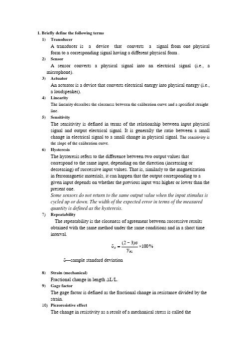
1. Briefly define the following terms1) TransducerA transducer is a device that converts a signal from one physicalform to a corresponding signal having a different physical form .2) SensorA sensor converts a physical signal into an electrical signal (i.e., amicrophone).3) ActuatorAn actuator is a device that converts electrical energy into physical energy (i.e.,a loudspeaker).4) LinearityThe linearity describes the closeness between the calibration curve and a specified straightline.5) SensitivityThe sensitivity is defined in terms of the relationship between input physicalsignal and output electrical signal. It is generally the ratio between a smallchange in electrical signal to a small change in physical signal. The sensitivity isthe slope of the calibration curve.6) HysteresisThe hysteresis refers to the difference between two output values thatcorrespond to the same input, depending on the direction (increasing ordecreasing) of successive input values. That is, similarly to the magnetizationin ferromagnetic materials, it can happen that the output corresponding to agiven input depends on whether the previous input was higher or lower than thepresent one.Some sensors do not return to the same output value when the input stimulus iscycled up or down. The width of the expected error in terms of the measuredquantity is defined as the hysteresis.7) RepeatabilityThe repeatability is the closeness of agreement between successive resultsobtained with the same method under the same conditions and in a short timeinterval.%100y σ)3~2(δFS ⨯=Rδ—sample standard deviation8) Strain (mechanical)Fractional change in length ΔL/L.9) Gage factorThe gage factor is defined as the fractional change in resistance divided by the strain.10) Piezoresistive effectThe change in resistivity as a result of a mechanical stress is called thepiezoresistive effect.11)direct piezoelectric effect.the phenomenon of generation of a voltage under mechanical stress is referred to as the piezoelectric effect.12)converse piezoelectric effect.The mechanical strain produced in the crystal under electric stress is called the converse piezoelectric effect.13)Numerical ApertureThe "acceptance cone" defines how much light will be accepted into the fiber andultimately how much remains in the fiber, and is referred to as the numerical aperture. 14)Extrinsic sensorThe optical fiber plays no part in achieving the modulating but simply acts as atransmission medium ; these are extrinsic sensors.15)Intrinsic sensors (fiber optic sensor)The optical fiber plays a major role in modulating the energy from the source; these are referred to as intrinsic sensors.16)Humiditya quantity representing the amount of water vapor in the atmosphere or a gas17)Absolute humidityAbsolute humidity is the mass of water vapor per unit volume of air.18)Relative humidityThe ratio of the actual vapor density to the theoretical maximum (saturation) vapordensity at the same temperature, expressed as a percentage. The relative humidity is the ratio of the actual vapor pressure to the saturation vapor pressure at given temperature. 19)Peltier effectWhen two dissimilar metals are connected together, a small voltage called athermojunction voltage is generated at the junction. This is called the Peltier effect.20)Law of Homogeneous ConductorsFor a given pair of homogeneous conductors forming a closed loop, the Seebeck emf depends only on the temperatures of the junctions, and not on the temperature distribution along the length of the conductors.21)Law of intermediate metalsA third (intermediate) metal wire can be inserted in series with one of the wires withoutchanging the voltage reading (provided that the two new junctions are at the sametemperature).If there is a third metal introduced into the thermocouple circuit , it will not adverselyeffect the reading, if and only if the two junctions of the third metal are at the sametemperatures .22)Bernoulli’s theoremBernoulli’s equation states that energy is approximately conserved across a constriction ina pipe.Bernoulli’s equation: P/(ρ•g) + ½v2/g + y = constant(ρ=density;g=acceleration of gravity ; v=fluid velocity; y=elevation )2. Describe the following devices and how they work1) Strain gageThe strain gauge usually consists of wire, baking, thinpaper, and lead welded. The wireis arranged in the form of a grid in order to obtain higher resistances.2) Parallel plate Capacitive SensorThe parallel plate Capacitive Sensor is a function of the distance d (cm) between theelectrodes of a structure, the surface area A (cm2) of the electrodes, and the permittivity ε0(F/m 1085.812-⨯for air) of the dielectric between the electrodes; therefore:d Ad AC 0r εεε==3) Differential Capacitive SensorA differential capacitor consists of two variable capacitors so arranged that they undergothe same change, but in opposite directions. The amplifier circuit, depending on itsconfiguration, can generate a voltage proportional to C1 - C2 or C1/C2 or (C1 - C2)/(C1 +C2).4) Variable Reluctance SensorsA typical single-coil variable-reluctance displacement sensor is illustrated in the Figurebelow. The sensor consists of three elements: a ferromagnetic core, a variable air gap, anda ferromagnetic plate.Based on change in the reluctance of a magnetic flux path. Self-inductance L of the coil is: Reluctance can be given as:5) Variable-Reluctance TachogeneratorsIt consists of a ferromagnetic, toothed wheel attached to a rotating shaft, a coil and amagnet. The wheel rotates in close proximity to the pole piece, thus causing the flux linkedby thecoil to change. The sensors output depends on the speed of the rotation of the wheeland the number of teeth.6) LVDTAn LVDT consists of three coils, a form and a core. The coils are wound on a hollow form.The primary is excited by some ac source. Flux formed by the primary is linked to the twosecondary coils, inducing an ac voltage in each coil. A core is inside the former. It canslide freely through the center of the form.In many applications, the two secondary coils are connected in series opposition.Then the two voltages will subtract; that is, the differential voltage is formed. When thecore is centrally located, the net voltage is zero. When the core is moved to one side, thenet voltage will increase.7) Compression Mode Piezoelectric Accelerometers Upright compression designs sandwich the piezoelectric crystal between a seismic mass2m WL R =0m l R S μμ=and rigid mounting base. A pre- load stud or screw secures the sensing element to themounting base.When the sensor is accelerated, the seismic mass increases or decreases the amount of compression force acting upon the crystal, and a proportional electrical output results.8)Shear mode accelerometerShear mode accelerometer designs bond, or “sandwich,” the sensing material between a center post and seismic mass. A compression ring or stud applies a preload force required to create a rigid linear structure. Under acceleration, the mass causes a shear stress to be applied to the sensing material. This stress results in a proportional electrical output by the piezoelectric material. They represent the traditional or historical accelerometer design.9)PsychrometerA psychrometer contains two identical thermometers. One sensor, the dry bulb ,measures the ambient temperature. The other sensor, the wet bulb, is in a wetted condition.In operation, water evaporation cools the wetted thermometer, resulting in a measurable difference between it and the ambient, or dry bulb measurement. When the wet bulbreaches its maximum temperature depression, the humidity is determined by comparing the wet bulb/dry bulb temperatures on a psychrometric chart10)Dunmore sensorThe Dunmore sensor uses a dilute lithium chloride solution in a polyvinylacetate binder on an insulating substrate. The resistance of the sensor, measured between a bifilar grid, is a function of the r.h. of the surrounding air.11)MOS CapacitorCCDs are typically fabricated on a p-type substrate. In order to implement the “buried” channel a thin n-type region is formed on its surface. A insulator, in the form of a silicon dioxide layer is grown on top of the n-region. Thecapacitor is finished off by placing one or more electrodes, also called gates, on top of the insulating silicon dioxide.12)Full frame transfer (FFT)It consists of a parallel CCD shift register, a serial CCD shift register and a signal sensing output amplifierThe image pixel are vertically transferred into a horizontal serial register, and the charges are horizontally shifted out.13)Interline transfer (ILT)The readout regions are interspaced between the imaging regions, and are shielded from the light.At the end of the integration period, the charges are transferred horizontally to the vertical readout registers in parallel, and then read out line-by-line in a manner similar to FFT.ILT does avoid smear but with the cost of the sensitive imaging areas.14)Frame transfer (FT)The array is grouped into two sections: the image section and the storage section. These two sections are identical, except that the storage section is shielded from the light. During the readout, charges are transfered line-by-line into the storage section by applying the same clocking to both sections. At the end of the integration period, charges in the storagesection are transferred line-by-line a manner similar to FFT.15)proximity sensorsProximity sensors detect objects that are near but without touching them. These sensors are used for near-field robotic operations.16)Time-of-flight sensorsTime-of-flight sensors estimate the range by measuring the time elapsed between thetransmission and return of a pulse17)Triangulation sensorsTriangulation sensors measure range by detecting a given point on the object surface from two different points of view at a known distance from each other. Knowing this distance and the two view angles from the respective points to the aimed surface point, a simple geometrical operation yields the range.18)Thermal Infrared DetectorsThermal infrared detectors convert incoming radiation into heat, raising the temperature of the thermal detector.19)Photon-type detectorsPhoton-type detectors react to the photons emitted by the object. The infrared radiation causes changes in the electrical properties of photon-type detectors.There are two main types of photon infrared detectors. One is called Photoconductive detector, which exhibit increased conductivity with received radiation. Another is named as Photovoltaic detector, this device converts received radiation into electric current.20)shock tubeConstruction of a shock tube is quite simple: it consists of a long tube, closed at both ends, separated into two chambers by a diaphragm, as shown in the Fig. below. A pressure differential is built up across the diaphragm, and the diaphragm is burst, either directly by the pressure differential or initiated by means of an externally controlled probe. Rupturing of the diaphragm causes a shock wave.The shock tube provides the nearest thing to a transient pressure “standard.”21)ThermocoupleA thermocouple consists of two electrical conductors made of different metals that are joined at one end.Note particularly that two junctions are always required. In general, one sense the desired or unknown temperature; this one we shall call the hot or measuring junction. The second will usually be maintained at a known fixed temperature; this one we shall refer to as the cold or reference junction. When the two junctions are at different temperatures, a voltage is developed across the junction.22)Bimetallic strip thermometerTwo dissimilar metals are bonded together into what is called a bimetallic strip. Since two metals have different coefficient of thermal expansion, one metal will expands more than does another metal as temperature increases, causing the bimetallic strip to curl upwards as sketched.23)RTDA resistance temperature detector is basically either a long, small diameter metal wirewound in a coil or an etched grid on a substrate, much like a strain gage. The resistance ofan RTD increases with increasing temperature.24)Three-wire BridgeA clever circuit designed to eliminate the lead wire resistance error is called a three-wireRTD bridge circuit, as sketched to the right.If wires A and B are perfectly matched in length (wires A and B have the same length, and thus the same resistance,), their impedance effects will cancel because each is in anopposite leg of the bridge. The third wire, C, acts as a sense lead and carries no current.25)ThermistorA thermistor is similar to an RTD, but a semiconductor material is usedinstead of a metal. A change in temperature causes the electrical resistance of the semiconductor material to change. P ositive temperature coefficient (PTC) and and negative temperature coefficient (NTC) units are available.26)Seismic (Absolute) Acc eleration PickupsIt consistis of a mass, a spring, and a damper arrangement, as shown in the Figure below.Fig……..y(t)= the absolute displacement of the mass Mx(t)= the absolute displacement of the basez-y=)()(txtz —the relative motion between the mass and the basem —massc —damping constantk —spring constantSeismic (Absolute) Displacement PickupsThe relative displacement z (the output of the sensor) is proportional to the applied displacement. A low value of ωn is needed (ωn should be much less than the lowest vibration frequency for accurate displacement measurement. )Seismic AccelerometerThe relative displacement z ( the output of the sensor) is proportional to the appliedacceleration. a high ωn is needed to measure accurately high-frequency. Increasing ωn will increase the range of frequency for which the amplitude-ratio curve is relatively flat;27)Seismic Velocity Pickup (moving coil type)One type of velocity transducer is based on a linear generator. When a coil cuts the magnetic field lines around a magnet, a voltage is induced in the coil, and this voltage is dependent on the speed of the coil relative to the magnet. The velocity pickup is designed like a displacement pickup, to have a low value of wn and to operate at angular frequencies well above wn so that the motion of the seismic mass is virtually the same as that of the casing but (almost) opposite in phase.28)The Orifice Plate FlowmetersAn orifice plate is a restriction with an opening smaller than the pipe diameter which is inserted in the pipe; Because of the smaller area the fluid velocity increases, causing acorresponding decrease in pressure.The flow ratee can be calculated from the measured pressure drop across the orifice plate 29)Ultrasonic FlowmetersUltrasonic Doppler Method:Doppler Equation :v f= K • Δf ;Doppler ultrasonic flowmeters reflect ultrasonic energy from particles, bubbles and/or eddies flowing in the fluid.Ultrasonic Transit-Time Method:The time difference between ultrasonic energy moving upstream and downstream in the fluid is used to determine fluid Velocity.Because transmitter-receiver B is situated downstream withrespect to A, the sound wave train from A to B will arrive soonerthan the train from B to A . This implies that the execution timefrom A to B is shorter than that from B to A.30)Electromagnetic FlowmetersThe measurement principle is based on Faraday’s Law of Magnetic Induction :ahomogeneous magnetic field is built up. An electrically conducting liquid flowsthrough this magnetic field.By the movement of the electrical conductor (liquid) a current gets induced which isproportional to the average flow velocity and the magnet field strength.。
迪伦克(Endress+Hauser)流动度量器系列用户操作手册说明书
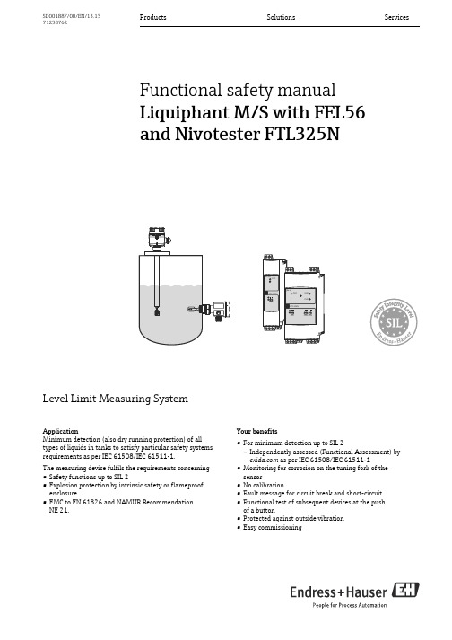
Products Solutions Services SD00188F/00/EN/13.1371238762Functional safety manualLiquiphant M/S with FEL56and Nivotester FTL325NLevel Limit Measuring SystemApplicationMinimum detection (also dry running protection) of all types of liquids in tanks to satisfy particular safety systems requirements as per IEC 61508/IEC 61511-1.The measuring device fulfils the requirements concerning •Safety functions up to SIL 2•Explosion protection by intrinsic safety or flameproof enclosure•EMC to EN 61326 and NAMUR RecommendationNE 21.Your benefits•For minimum detection up to SIL 2–Independently assessed (Functional Assessment) by as per IEC 61508/IEC 61511-1•Monitoring for corrosion on the tuning fork of the sensor•No calibration•Fault message for circuit break and short-circuit •Functional test of subsequent devices at the pushof a button•Protected against outside vibration•Easy commissioningLiquiphant M/S with FEL56 and Nivotester FTL325N2Endress+HauserTable of contentsSIL declaration of conformity . . . . . . . . . . . . . . . . . . . . .3Introduction. . . . . . . . . . . . . . . . . . . . . . . . . . . . . . . . . . . .4General depiction of a safety system (protection function) . . . 4Structure of the measuring system . . . . . . . . . . . . . . . .5Level limit measuring system . . . . . . . . . . . . . . . . . . . . . . . . . . . . 5Safety function . . . . . . . . . . . . . . . . . . . . . . . . . . . . . . . . . . . . . . . . 5Permitted device types . . . . . . . . . . . . . . . . . . . . . . . . . . . . . . . . . 6Safety function data . . . . . . . . . . . . . . . . . . . . . . . . . . . . . . . . . . . 7Supplementary device documentation . . . . . . . . . . . . . . . . . . . . 7Settings and installation instructions . . . . . . . . . . . . . .9Installation instructions . . . . . . . . . . . . . . . . . . . . . . . . . . . . . . . . 9Response in operation and failure . . . . . . . . . . . . . . . 10Recurrent function tests of the measuring system . 10Appendix . . . . . . . . . . . . . . . . . . . . . . . . . . . . . . . . . . . . 11Specific values and wiring options for themeasuring system . . . . . . . . . . . . . . . . . . . . . . . . . . . . . . . . . . . . 11Exida Management Summary. . . . . . . . . . . . . . . . . . . 18Supplementary Documentation . . . . . . . . . . . . . . . . . . . . . . . . . 20Liquiphant M/S with FEL56 and Nivotester FTL325NEndress+Hauser 3SIL declaration of conformitySIL-04001B-00-A2Liquiphant M/S with FEL56 and Nivotester FTL325N4Endress+HauserIntroductionGeneral depiction of a safety system(protection function)Parameter tables for determining Safety Integrity Level (SIL)The following tables are used to define the reachable SIL or the requirements pertaining to the“Average Probability of Dangerous Failure on Demand” (PFD av ), the “Hardware Fault Tolerance” (HFT)and the “Safe Failure Fraction” (SFF) of the safety system. The specific values for the Liquiphant M/S +Nivotester FTL325N measuring system can be found in the Appendix.Permitted probabilities of dangerous failures on demand of the complete safety related systemdependent on the SIL (e.g. exceeding a defined MIN level/switch point) (Source: IEC 61508, Part 1):The following table shows the achievable Safety Integrity Level (SIL) as a function of the probability fraction of safety-oriented failures and the "hardware fault tolerance" of the complete safety system for type B systems (complex components, not all faults are known or can be described).For general informationen about SIL please refer to: /silSIL PFD av4≥ 10-5 to < 10-43≥ 10-4 to < 10-32≥ 10-3 to < 10-21≥ 10-2 to < 10-1SFFHFT 01 (0)1)1)In accordance with IEC 61511-1 (FDIS) (chapter 11.4.4), the HFT can be reduced by one (values in brackets) if the devices used fulfil the following conditions:- The device is proven in use,- Only process-relevant parameters can be changed at the device (e.g. measuring range, ...),- Changing the process-relevant parameters is protected (e.g. password, jumper, ...),- The safety function requires less than SIL 4.All conditions apply to Liquiphant M/S + Nivotester FTL325N.2 (1)1< 60%not allowed SIL 1SIL 260% to < 90%SIL 1SIL 2SIL 390% to < 99%SIL 2SIL 3≥ 99%SIL 3Liquiphant M/S with FEL56 and Nivotester FTL325NEndress+Hauser 5Structure of the measuring systemLevel limit measuring systemThe measuring system's devices are displayed in the following diagram (example).1FEL - Electronic insert A Nivotester FTL325N (one-channel)2Liquiphant M/S B Nivotester FTL325N (three-channel)Safety functionThe safety function applies to all settings in MIN safety (monitoring of the covered state) and use of the NO contacts of the level relays.The following settings are permitted for the safety function:The level relay always works in quiescent current safety; i.e. the relay releases when:•The switch point is undershot (level falls below response height)•A detected fault occurs •The mains voltage failsIn addition to the level relay, the alarm relay works in quiescent current safety and releases when:•One of the following faults occurs: –the sensor connection is interrupted –the sensor connection short circuits •The mains voltage failsDevice SettingAs-delivered state Liquiphant•Density switch setting: 0,5•Density switch setting: 0,7Density switch setting: 0,7"MIN" safety"MAX" safetyNivotesterFTL325N-#3#3Error current signal > 2,1 mAError current signal > 2,1 mA All settings except" S function" (see section "Settings and instal-lation instructions")Three-channel operationThe DIL switch for fault messaging(short-circuit-, and circuit break-monitoring)must be set to the ON position.Failure switch "ON"NivotesterFTL325N-#1#1Error current signal > 2,1 mAError current signal > 2,1 mA One-channel operationThe DIL switch for fault messaging(short-circuit-, and circuit break-monitoring)must be set to the ON position.Failure switch "ON"When the alarm relay releases, the level relay also releases.Liquiphant M/S with FEL56 and Nivotester FTL325N6Endress+HauserPermitted device typesThe details pertaining to functional safety in this manual relate to the device versions listed below and are valid as of the specified firmware and hardware version.Unless otherwise specified, all subsequent versions can also be used for safety instrumented systems.A modification process according to IEC 61508 is applied for device changes.Valid device versions for safety-related use:Valid firmware version: as of 01.00.00Valid hardware version (electronics): as of 01.00Valid device versions for safety-related use:Valid firmware version: as of 01.00.00Valid hardware version (electronics): as of 01.00Valid device versions for safety-related use:Liquiphant M FTL50, FTL50H, FTL51, FTL51C, FTL51H+ FEL56Feature Designation Option model 010Approvalall 020Process connection all 030Probe length; Type all 040Electronics; Output 6FEL56; SIL NAMUR (L-H signal)050Housing; Cable Entry all 060Additional optionsallLiquiphant S FTL70, FTL71+ FEL56Feature Designation Option model 010Approvalall 020Process connection all 030Probe length all 040Electronics; Output 6FEL56; SIL NAMUR (L-H signal)050Housing; Cable entry all 060Additional option all 070ApplicationallNivotester FTL325N Feature Designation Option model 010ApprovalG H N P T WATEX II 3(1)G Ex nC/A (ia) IIC T4, SIL, IECEx Zone 2ATEX II (1)GD (Ex ia) IIC, WHG, SIL, IECEx (Ex ia) IIC (Liquiphant M / Liquiphant S)NEPSI (Ex ia) IIC, SIL (Liquiphant M / Liquiphant S)FM IS Cl. I, II, III Div. 1 Gr. A-G, SIL (Liquiphant M / Liquiphant S)CSA IS Cl. I, II, III Div. 1 Gr. A-G, SIL (Liquiphant M / Liquiphant S)TIIS Ex ia IIC, SIL, labeling in Japan020Housing all 030Power Supply all 040Switch outputallLiquiphant M/S with FEL56 and Nivotester FTL325NEndress+Hauser 7Safety function data•The mandatory settings and data for the safety function can be found in chapter "Safety function", →ä5 and chapter "Settings and installation instructions", →ä9.•The measuring system reacts in ≤ 1,4 s.Supplementarydevice documentationMTTR is set at eight hours.Safety systems without a self-locking function must be monitored or set to an otherwise safe state after carrying out the safety function within MTTR.Liquiphant M FTL50, FTL50H, FTL51, FTL51H, FTL51C DocumentationContents CommentTechnical Information•FTL50, FTL50H, FTL51, FTL51H:TI00328F/00/EN •FTL51C:TI00347F/00/EN –Technical data –Accessories–The documentation is available on the Internet:→ .Operating Instructions •FTL50, FTL51:KA00143F/00/A6KA00163F/00/A61)•FTL50H, FTL51H:KA00144F/00/A6KA00164F/00/A61)•FTL51C:KA00162F/00/A6KA00165F/00/A61)1)with aluminium housing / separate terminal compartment.–Installation –Wiring –Operation–Commissioning –Troubleshooting –Repair–Maintenance–The documentation is supplied with the device.–The documentation is also available on the Internet:→ .Safety instructions depending on the selected version"Approval"Safety, installation andoperating instructions for devices, which are suitable for use in potentially explosive atmospheres or as overfillprotection (WHG, German Water Resources Act).Additional safety instructions (XA, ZE) are supplied with certified device versions. Please refer to the nameplate for the rele-vant safety instructions.Liquiphant S FTL70, FTL71Documentation Contents CommentTechnical Information TI00354F/00/EN –Technical data –Accessories –The documentation is available on the Internet:→ .Operating Instructions KA00172F/00/A6KA00173F/00/A61)1)with aluminium housing / separate terminal compartment–Installation –Wiring –Operation–Commissioning –Troubleshooting –Repair–Maintenance–The documentation is supplied with the device.–The documentation is also available on the Internet:→ .Safety instructions depending on the selected version"Approval"Safety, installation andoperating instructions for devices, which are suitable for use in potentially explosive atmospheres or as overfillprotection (WHG, German Water Resources Act).Additional safety instructions (XA, ZE) are supplied with certified device versions. Please refer to the nameplate for the rele-vant safety instructions.Liquiphant M/S with FEL56 and Nivotester FTL325N8Endress+HauserNivotester FTL325N Documentation Contents CommentTechnical Information TI00353F/00/EN –Technical data –Accessories –The documentation is available on the Internet:→ .Operating Instructions •One-channel device:KA00170F/00/A6 •Three-channel device:KA00171F/00/A6–Installation –Wiring –Operation–Commissioning –Troubleshooting –Repair–Maintenance–The documentation is supplied with the device.–The documentation is also available on the Internet:→ .Safety instructions depending on the selected version"Approval"Safety, installation andoperating instructions for devices, which are suitable for use in potentially explosive atmospheres or as overfillprotection (WHG, German Water Resources Act).Additional safety instructions (XA, ZE) are supplied with certified device versions. Please refer to the nameplate for the rele-vant safety instructions.Liquiphant M/S with FEL56 and Nivotester FTL325NEndress+Hauser 9Settings and installation instructionsInstallation instructionsPlease refer to the Compact Instructions (KA) for information regarding the correct installation of Liquiphant M/S + Nivotester FTL325N.Since the application conditions have an effect on the safety of the measurement, pay attention to the notes in the Technical Information (TI) and Compact Instructions (KA).The ambient conditions for the Nivotester FTL325N must correspond to IP54 (in accordance with EN 60529).The manuals on setting the devices can be found in the section "Supplementary device documentation", →ä7.Settings for Liquiphant M/S (FEL56):•The density switch setting must be configured according to the density range of the medium.•The settings of the safety mode has an effect on the function. The DIL switch must be set to MIN for minimum detection in a SIL application.Settings for Nivotester FTL325N-#3#3 (three-channel version):Observe the following for the Nivotester FTL325N-####: The operator must use suitablemeasures (e.g. current limiter, fuse) to ensure the relay contact characteristics are not exceeded:•U ≤ 253 V AC 50/60 Hz , I ≤ 2 A, P ≤ 500 VA at cos ϕ ≥ 0,7 or •U ≤ 40 V DC, I ≤ 2 A, P ≤ 80 WChanges to the measuring system and settings after start-up can impair the protection function!Liquiphant M/S with FEL56 and Nivotester FTL325N10Endress+HauserResponse in operation and failureThe response in operation and failure is descriped in the documentation, which can be found in the section "Supplementary device documentation", ä7.RepairIn the event of failure of a SIL-labeled Endress+Hauser device, which has been operated in a protection function, the "Declaration of Contamination and Cleaning" with the corresponding note "Used as SIL device in protection system" must be enclosed when the defective device is returnedRecurrent function tests of the measuring systemThe operativeness of the minimum detection must be checked annually if the PFD av values given in the Appendix are used.The check must be carried out in such a way that it is proven that the minimum detection functions perfectly in interaction with all components. This is guaranteed when the response height is lowered in an emptying process. If it is not practical to empty to the response height, suitable simulation of the level or of the physical measuring effect must be used to make the level sensor respond.If the operativeness of the level sensor/transmitter can be determined otherwise (exclusion of faults that impair function), the check can also be completed by simulating the corresponding output signal.In the case of recurrent tests, each permitted setting must be checked, especially whether all the alarm switches are set to ON.Note the following points for the function test:•Each individual channel must be checked e.g. by lowering the level.•Relay contact switching can be checked by using a hand multimeter at the terminals or by observing the minimum detection components (e.g. horn, adjuster).•In multi-channel devices, all channels which do not carry out a safety function must beincluded in the recurrent function tests if faulty functioning cannot be detected by any other means.•As a positive test result, an uncovered tuning fork must be detected and trigger the alarm for minimum detection.•If fork uncovering is not detected during the recurrent test, the monitored process must be set to a safe state by means of additional or other measures and/or kept in the safe state until the safety system is repaired.AppendixSpecific values and wiring options for the measuring system The tables show the specific values and wiring options for the measuring system.Note the following points on the tables below:•The PFD av values for multichannel systems already contain common cause failures for theassociated wiring scheme.•The PFD av values are only valid for the associated wiring scheme. Wiring schemes other than those shown in the Appendix were not assessed and thus do not bear any information relevant to safety. Using NC contacts instead of NO contacts requires further consideration of theinstallation means.•The wiring scheme shows the number of devices (Liquiphant and Nivotester) and the limitrelay contact circuits (open, when the sensor signals uncovering).•Fault messaging (circuit break/short-circuit) must be switched on for each channel thatperforms a safety function.•With several devices in a wiring scheme, they all indicate the same displayed settings.For safety related use of the Liquiphant M/S for MIN detection, the following application errors must be excluded:•Permanent and/or heavy build-up or "non-Newtonian media"•Solid proportions of the medium with a diameter > 5,0 mm (0.2in)•Corrosion: The Liquiphant may only be used in media to which the process-wetted parts are resistant. If coated sensors are used, measures must therefore be taken to ensure that there is no damage during installation and operation.The errors may cause that the demand mode of the safety function is not detected and theLiquiphant will not switch as intended.Exida Management SummaryExida Management Summary 2Exida Management Summary 1Exida Management Summary 4 Exida Management Summary 3Supplementary Documentation Safety in the Process Industry - reducing risks with SIL CP01008Z/11/EN.Liquiphant M/S with FEL56 and Nivotester FTL325NEndress+Hauser21Liquiphant M/S with FEL56 and Nivotester FTL325N 22Endress+HauserLiquiphant M/S with FEL56 and Nivotester FTL325NEndress+Hauser2371238762。
电力行业——专业术语英文对照表

电力行业——专业术语英文对照表一.电气名词Electric items交(直)流Alternating (direct) current短路电流Short-circuit current起始次暂态短路电流Initial subtransient short-circuit current 冲击电流Impulse current稳态短路电流Steady state short-circuit current临界电流Critical current切断电流Rupturing current熔断电流Blow-out current故障电流Fault current计算电流Calculating current极限有限电流Limit effective current过电流Over current逆电流Inverse current整定电流Setting current额定电流Rated current电流密度Current density短路电流最大有效值Maximum effective value of short-circuit current高压High-voltage , High-tension低压Low-voltage , Low-tension计算电压Calculating voltage激磁电压Exciting voltage冲击电压Impulse voltage临界电压Critical voltage残留电压Residual voltage击穿电压Puncture voltage脉动电压Pulsating voltage供电电压Supply voltage电力电压Power voltage照明电压Lighting voltage灯丝电压Filament voltage额定电压Rated voltage电压损失Voltage loss过(欠)电压Over (under) voltage线路电压Line voltage电压降Voltage drop工作电压Working voltage一次电压Primary voltage二次电压Secondary voltage电源Electric source (power supply)自控电压Power supply for process control6kV 控制闪光电源Flashing supply for 6kV control 工作电源Working power supply (electric source) 保安电源Emergency power supply (electric source) 直流稳压电源Stabilized D.C. source控制电源Control supply直流电源D.C. source交流电源A.C. source负荷计算Load calculation设备容量Installed capacity需要容量Electric demand功率因数Power factor安装高度Mounting height耐电压Breakdown voltage工频耐压High-voltage test with working frequency 表面闪络Surface flash-over直流泄漏D.C. leakage体电阻率Volume resistivity介质损失角Dielectric loss angle击穿强度Puncture intensity电压等级Voltage grade比重Specific gravity性能Feature相序Phase sequence瞬时Instantaneous倾角Angle of inclination跨度Span正极Positive pole负极Negative pole截面(积) Cross section area辅助电源Auxiliary source遮断容量Interrupting capacity载流量Current-carrying capacity校正系数Correction factor连续负荷Continuous load长期载流量Continuous capacity长时间额定值Longtime rating电动机堵转电流Locked-rotor motor current限定负荷Limited load电感负荷Inductive load感应电流Induced current二.线路(母线、回路)Lines (Bus , circuits)母线Bus-bar合闸电源母线Closing power source bus闪光母线Flashing-bus备用母线Spare bus装在支柱上的插接式母线Post-supported plug-in bus way装在吊钩上的插接式母线Hook-supported plug-in bus way装在支架上的插接式母线Bracket-supported plug-in bus way 小母线Miniature bus电源小母线Power supply miniature bus操作小母线Operating miniature bus事故信号小母线Miniature bus for fault signal闪光小母线Flashing miniature bus主母线Main bus直流主母线D.C. main bus预告母线Prewarning bus干线Main line照明干线Lighting main line接地干线Grounding main line插座干线Receptacle main line电压干线Voltage main line端子出线Terminal outgoing中性线Neutral支线Branch-line引入线Lead-in电气线路Electric circuit交流配电线路A.C. distribution circuit直流配电线路D.C. distribution circuit事故照明线路Emergency lighting circuit控制线路Control circuit接地或接零线路Grounding or neutralizing circuit信号线路Signal circuit有接地极的接地线路网Grounding with grounding electrodes 定子绕组测温回路Temperature measuring circuit for stator winding接地信号回路Grounding signal circuit闪光信号回路Flashing-signal circuit开阀回路Circuit for opening valve关(闭)阀回路Circuit for closing valve开度计回路Circuit for opening meter电流测量回路Current-measuring circuit差动保护回路Differental protective circuit过流保护回路Over-current protective circuit合闸回路Closing circuit停车延时回路Delayed shutdown circuit掉闸回路Trip circuit激磁回路Exciting circuit备用回路Spare circuit主回路Main circuit馈路Feeder circuit现有回路Existing circuit单线回路Single-wire circuit接地回路Earthed circuit有电压的电路Live circuit三.设备Equipments高压开关柜H.V. switchgear动力配电箱Power distribution cabinet电源配电箱Source distribution cabinet直流配电屏D.C. switchboard (distribution panel)交流低压配电屏A.C.L.V. switchboard (distribution panel)静电电容器柜Static capacitor cabinet多种电源插销箱Receptacle box for miscellaneous power supplies控制箱Control cabinet照明配电箱Lighting (distribution panel)连接箱Junction box出线盒Outlet box开关箱Switch box控制台Console分段屏Sectionalizing panel进线屏Incoming line panel电控箱Electric control panel边屏Side board端子箱T erminal box供电盘Power supply box瓶车箱Synchronizing cabinet感应调压器专用变压器高压柜Special transformer H.V. cabinet for inductionvoltage regulator电压互感器柜Potential transformer cabinet信号屏Signal panel浮充屏Floating panel蓄电池屏Battery panel充电屏Charging panel母线联络柜Bus tie cabinet转换开关Transfer switch电压表转换开关Voltmeter change-over switch铁壳开关Metal-clad switch (Iron-clad switch)管式熔断器Cartridge fuse真空断路器Vacuum circuit breaker (V.C.B.)自动开关Automatic switch高压负荷开关H.V. load break switch三极高压断路器3-pole HV circuit-breaker刀开关Knife switch转换开关Transfer switch双极铁壳开关2-pole iron-clad switch风扇变速开关Fan speed regulator switch密闭照明灯开关Hermetic lighting switch防爆照明灯开关Explosion-proof lighting switch行程开关Limit switch高压隔离开关H.V. disconnecting switch明装单极板钮开关Surface-mounted single-pole toggle switch 暗装单极板钮开关Flush-mounted single-pole toggle switch 三路开关Three-way switch气密式组合开关Hermetic packet type switch防护式开关Guard type switch联锁开关Interlock switch操作方式选择开关Selecting switch for types of operation控制电源开关Switch for control supply主令开关Master switch (controller)多切点切换开关Multi-point change-over switch按钮Push-button控制按钮Control push-button防爆控制按钮Explosion-proof control push-button事故紧急按钮Emergency stopping push-button起动按钮Starting push-button停止按钮Stopping push-button现场按钮Push-button in field挡板damper音响解除按钮Push-button for sound release起动器Starter磁力起动器Magnetic starter综合起动器Combination starter (Magnetic starter combination)电力变压器Power transformer调压变压器Voltage regulating transformer电压互感器Potential transformer电流互感器Current transformer照明变压器Lighting transformer三相三绕组变压器3-phase tertiary winding transformer高压试验变压器H.V. testing transformer局部照明变压器Local lighting transformer多量程仪用电流互感器Multi-range current transformer for measurement降压变压器Step-down transformer伺服电动机Servo-motor双电压电动机Dual-voltage motor感应电动机Induction motor交流异步电动机A.C. asynchronous motor同步电动机synchronous motor三相滑环感应电动机3-phase slip-ring induction motor三相鼠笼感应电动机3-phase squirrel-cage induction motor 绕线式电动机Wound-rotor induction motor反应式电动机Reaction motor柴油发电机Diesel generator励磁发电机Excitation generator明装双极插座Surface-mounted 2-pole receptacle暗装双极插座Flush-mounted 2-pole receptacle双极带接地插座2-pole receptacle with grounding contact单相三孔明插座Surface-mounted single phase 3-pole receptacle防护式明装三相四孔插座Guard type surface-mounted 3-phase 4-pole receptacle配照型灯Standard dome lighting fitting搪瓷深照型灯Enameled high bay lighting fitting防水防尘灯Water and dust proof lighting fitting安全灯Safety lighting fitting隔爆灯Explosion-proof lighting fitting弯灯Goose-neck light壁灯Wall light高压水银灯High pressure mercury vapor lighting fitting 投光灯Flood-light (projection light)信号灯Signal lamp天棚灯Ceiling-mounted lighting fitting局部照明灯Local lighting fitting灯座Lamp holder事故照明灯Emergency lighting fitting高压水银荧光灯H.P. mercury fluorescent lighting fitting 广照型工厂灯Wide lit type industrial fitting深照型灯具High bay lighting fitting白炽灯具Incandescent lamp (bulb)圆球型灯Globe lamp嵌入式荧光灯flush type fluorescent lighting fitting红色障碍灯Red obstruction lamp for aviation厂区道路照明灯Street lighting in plant area路灯Street lamp视孔灯Inspection hole lamp立杆弯灯goose-neck post lamp , pole lamp模拟报警信号Semigraph and alarm signal自整角机Selsyn励磁机Exciter显示器Display电位器Potentiometer内电阻Internal resistance固定电阻(器) Fixed resistance脱扣Release , trip分励Shunt trip特殊失压脱扣器Special no-voltage release“或”开关放大器“Or” switch amplifier制动器Brake电容Capacitor整流器Rectifier镇流器Chock分流器Shunt油变阻器Oil immersed rheostat频敏电阻器Frequency sensitive rheostat滑线变阻器Sliding rheostat蜂鸣器Buzzer电机加热器Space heater (for motor)空气断路器电机操作机构Motor operating mechanism for air circuit-breaker可控硅励磁装置Silicon controlled rectifier excitation device 保护装置Protective device (element)闪光装置Flashing device接闪装置(避雷器) Lightning arrester断相保护Phase failure protection四.保护、继电器Protection , relays信号继电器Signal relay过电流继电器Over-current relay电压继电器Voltage relay时间继电器Time relay中间继电器Auxiliary relay热继电器Thermal relay温度继电器T emperature relay瓦斯继电器Gas relay控制电源中间继电器Auxiliary relay for control supply自动操作继电器Relay for auto-operation低电压继电器Under-voltage relay过电压继电器Over-voltage relay联锁继电器Interlock relay冲击继电器Impact relay合闸位置继电器Close position relay逆流继电器Reverse-current relay差流继电器Differential current relay差动继电器Differential relay电流继电器Current relay功率继电器Power relay接地继电器Earthing relay重合闸继电器Reclosing relay同步继电器Synchronous relay速动继电器Quick acting relay定时限继电器Definite time relay光电继电器Photoelectric relay电子继电器Electronic relay电磁式继电器Electromagnetic relay电动式继电器Electrodynamic relay气压继电器Gas-pressure relay继电器常开触点Relay N.O. contact继电器常闭触点Relay N.C. contact继电器保护触点(常开) Relay holding contact (N.O.)能自动返回的常闭按钮触点Self-return button with N.C. contact模拟信号触点Contact for semigraph signal强励磁接点Shock excitation contact电感线圈Induction coil电流线圈Current coil脱扣线圈Trip coil合闸线圈Close coil释放线圈Releasing coil掉闸线圈Tripping coil予告信号Prewarning signal掉闸回路断线信号Breakage signal of trip circuit断路器事故掉闸信号Fault trip signal of breaker掉闸音响信号Tripping audible signal重瓦斯预告信号Heavy gas prewarning signal温度预告信号Temperature prewarning signal手动、自动操作时事故信号Fault signal in manual/automatic operation保护掉闸Protective trip控制掉闸Control trip手动跳闸Manual trip变电所紧急停车Emergency shutdown at substation工艺故障Fault in process励磁故障Fault in excitation工作电源失电报警No-voltage alarm of working electric source工作电源分合闸On and off of working electric source工作电源投入Throw-in of working electric source保安电源送电supply of emergency electric source运转指示Indicating of operation投入指示Indicating of throw-in同步指示Indicating of synchronism延时停车Delayed shutdown电源切除Switch off the power supply速断及过流断通Instantaneous trip and over-current off/on自保持Self-holding自锁Self-lock联锁Interlocking绝缘监视Insulation supervision电压监视Voltage supervision联锁解除Release of interlock工作、保安电源切换Transfer of working and emergency power supply发电机与工作母线并车Synchronization of generator to working bus重瓦斯保护Heavy gas protection开或闭超扭矩保护Over-torque protection during opening and closing valve电机起动顺序Sequence of motor starting铭牌框注字Name plate denotation (inscription)五.电气仪表Electric instruments电流表Ammeter电压表Voltmeter三相三线有功电度表Three-phase three-wire kilowatt-hour meter , kWh meter单相电度表Single-phase kilowatt-hour meter三相无功电度表Three-phase kilovar-hour meter有功功率表Active power meter , kilowatt meter无功功率表Reactive power meter , kilovar meter三相瓦特表(功率表) Three-phase watt meter功率因数表Power factor meter频率表Frequency meter验电流器Galvanoscope欧姆表Ohmmeter相位表Phase meter转速表Tachometer波长表Wave-length meter三相四线制标准电度表3-phase 4-wire standard watthour-meter过载电流表Overload ammeter低功率因数瓦特表Low power-factor wattmeter交直流两用钳型电流表A.C./D.C. multi-purpose tongtester兆欧表Megger , Megohmmeter万用表Avometer微安表Microammeter毫安表Milliammeter各种测量仪表Various kind of measuring instruments接地电阻测量仪Earthing resistance tester真空管电压表Vacuum tube voltmeter电动秒表Electric second-meter六.防雷Lightning protection避雷装置Lightning protector避雷针Lightning rod避雷带Strap type lightning protector避雷网Network of lightning protector避雷针支架Lightning rod support避雷针尖Tip of lightning rod避雷针拉铁Brace for lightning rod避雷器Lightning arrester , surge discharger球型避雷器Spherical arrester管形避雷器Tubular arrester阀形避雷器Auto-valve arrester低压避雷器Low voltage arrester角形避雷器Horn arrester多隙避雷器Multigap arrester铝避雷器Aluminum cell arrester氧化膜避雷器Oxide film arrester击穿保险器Puncture lightning arrester雷击Lightning stroke直接雷击Direct lightning stroke感应雷击Induction lightning stroke雷电日Thunderbolt days雷电或然率Lightning and thunder probability 触电Electric shock静电感应Electrostatic induction七.接地Grounding , earthing接地保护Ground protection , earth protection 防雷接地Grounding for lightning保护接地Protective earthing人工接地Artificial grounding工作接地Working grounding , working earthing 重复接地Multiple earthing屏蔽接地Screen earthing , shielding ground中性点接地Neutral point grounded接地系统Grounding system , earthing system 接地故障Ground fault , earth fault单相接地Single phase earthing母线接地Bus ground接地装置Grounding device , earthing device引下线Down-lead , down conductor引下线固定Clamping plate of support for fixing 支架夹板Down lead引下线固定支脚Support for fixing down lead接地线Ground connector接地干线Ground(ing) main , (bus)接地网Grounding network , earthing network接地极Earth electrode (pole)接地电阻Earth resistance接地电路Earth (ground) circuit连接条Connecting strip断接卡Connecting clamp八.室、所Room , Substation贮藏室Storage套间Compartment蓄电池室Battery room控制室Control room配电室Distribution room维修间Repair room变电所Substation高压配电室H.V. distribution room休息室Rest room九.电修车间设备Equipments of electric repair砂轮机Emery wheel grinder台钻Bench drilling machine交流电焊机A.C. welding machine移动式空气压缩机Portable air compressor手电钻Electric hand drill单速手摇绕线机Single speed hand winding machine导线钳压器Wire jointing press-clamp油压千斤顶Hydraulic jack电吹尘器Electric dust cleaner存放柜Store chest高压试验变压器H.V. testing transformer泄漏试验变压器Leakage testing set大电流发生器Strong current generator油浸自冷感应调压器Oil-immersed self-cooled inductionvoltage regulator多量程仪用电流互感器Multi-range current transformer for measurement仪用电感互感器Instrumental voltage transformer单相自耦变压器Single-phase auto-transformer三相自耦变压器3-phase auto-transformer硅整流器Silicon rectifier仪表试验台T esting stand for instrument接触器,继电器试验台Relay and contactor testing stand慢扫描示波器Slow scanning oscillograph交流电子稳压器A.C. electronic voltage stabilizer携带式交流电桥Portable A.C. electric bridge接地电阻测量仪Earthing resistance tester电缆故障探伤仪Cable fault detector直流单臂电桥D.C. single-arm electric bridge , Wheatstone bridge十.材料Material绝缘包布Insulating tape填料Filler , packing绝缘膏Insulating compound电缆膏Cable compound防腐油Anti-corrosive oil沥青漆Bituminous varnish绝缘漆Insulating varnish瓷漆Enamel varnish有色金属Non-ferrous metal黑色金属ferrous metal白金属White metal云母Mica环氧树脂Epoxy resin聚氯乙烯Polyvinyl chloride , PVC 蜡Wax滑石粉Talc powder电胶木Bakelite聚丙烯外壳Polyacrylic cover耐油橡胶管Oil-proof rubber tubes 接地铜线Grounding copper wire 垫圈Pad塑料绝缘线Plastics insulated wire 橡套电缆Rubber sheathed cable 中间接头Splice填充剂Filling agent绝缘电线Insulated wire移动软电缆Movable flexible cable 补偿导线Extension wire套管Bushing母线槽Busway悬索Cable suspension滑触线Trolley conductor镀锌煤气管Galvanized gas pipe镀锌角钢Galvanized steel angle镀锌扁钢Galvanized steel strap钢丝绳Steel wire rope电笛Siren电磁阀Electromagnetic valve连接片Connecting link切换片Transfering link端子排T erminal board半导体二极管Semiconductor diode 开度计Opening meter逻辑元件Logical element接线盒Junction box仪表槽板Instrument trunking电缆吊架Cable hanger出线套Outgoing line sleeve十一.图名Drawings , diagrams电气图纸目录Contents of electric drawings电力系统图Electric power system diagram照明系统图Lighting system diagram电力平面布置图Electric power layout plan照明平面布置图Lighting layout plan单线图One line diagram控制箱面部布置图Surface arrangement of control box 背部接线图Back wiring (diagram)外部接线图External (outside) wiring diagram内部接线图Internal (inside) wiring diagram控制原理图Principle control diagram原理图Schematic diagram展开图Developed diagram电气标准图Electric standard drawing电气施工图Electric working drawing复用图Reproducibles (drawing)电缆联系图Cable hook-up diagram转换开关接点图Contact diagram of transfer switch箱侧视图Side view of box正视图Front view , facade背视图Back view剖面图Section参考图Reference drawing电缆敷设图Cable laying diagram箱内框架布置图Arrangement of frames inside the cabinet控制箱台面展开图Surface developed diagram of console出线端子示意图Schematic diagram of terminal outgoing lines 端子接线图Diagram of terminal connections电气管线表List of wire , cable and conduits设备材料表List of equipment and materials十二.表头Tables电力系统图Power system diagram引入线Lead in保护设备Protective device型号Type额定值Rating整定值Setting主启动设备回路Circuit to starting device导线型号、芯数、截面及管径Conductor type , cores , section & diameter of conduit线长Wire length管长Conduit length启动设备Starting device型号规格Type , specification保护元件Protective element计量装置Calculating device用电设备主回路Main circuit of electric equipment控制回路Control circuit控制装置Control device用电设备Electric equipment设备容量Consumer capacity生产设备Production equipment位号No. of location名称Name备注Remarks引入线Feed in配电箱Distribution cabinet型号及编号Type and No.开关型号Switch type保护装置Protective device回路编号Circuit No.相别Phase灯数Number of lamps插座数Number of receptacles电缆编号No. of line起点Starting终点Ending母线截面Section of bus零母线Neutral bus屏编号Panel No.型号及方案号Type and variant No.控制原理图号Principle control diagram工艺位号Process item No.十三.标准图词汇Terms from standard DWG电工系统图图形符号Graphic symbols for electric system交流电的相别A.C. phase sequence直流电的正负极D.C. positive and negative poles有中性点引出线的星形连接的三相绕组Star-connected three phase windings withneutral outlet开口三角形连接的三相绕组3-phase winding with open delta connection互相连接的导线Cross connection of wires不连接的跨越导线Crossing wires not in contact with eachother可拆卸的电气连接Removable connection电缆终端头Pothead of cable or cable end自耦变压器Auto-transformer感应调压器Induction voltage regulator凸极同步电动机Salient pole synchronous motor带接换装置的蓄电池组Accumulator battery with tap-changers 空气断路器Air circuit-breaker保持触点Holding contact热元件Thermal element自动复位的操作开关Spring-return operating switch插接器Plug-in connector电喇叭Horn电炉Electric furnace分流器Shunt可控硅整流箱屏Silicon controlled rectifier box panel直流配电屏D.C. distributing panel磁力起动器组Magnetic starter group自动开关箱Automatic switch box行程开关Limit switch局部灯Local lighting fitting荧光灯列Series fluorescent lighting fitting防护式灯开关Protective switch导线引上Conductors turning up导线引下Conductors turning down导线由上引来Conductors turning from above导线由下引来Conductors turning from below电缆沟Cable trench调压器Voltage regulator隔离变压器Isolating transformer击穿保护器Puncturing safety device晶体管Transisorized diode地坪Grade level电缆与水管平行Cable running parallel to a water supply pipe 电缆与热力管道交叉敷设Cable running across heat pipeline 车道Drive way电缆穿管与管道交叉Cable protective pipe across a pipeline 双(单)侧支架电缆沟Trench with rack on both sides (one side) 室外地坪Outdoor grade跨接线Jumper金属软管Flexible metal tube过渡接头Adapter电气工程及其自动化专业术语翻译transistor 晶体管audion 三极管capacitance 电容Diesel 柴油机AC- motors 交流电机transistorcoupling 联结耦合current carrying capacity 载流能力(最大允许电流)conductivity 传导性in isolation 绝缘lead 导线leakage current 泄漏电流inductance 感应系数loops 线圈macroprocessor 微处理器multimedia show 多媒体展示medium-power distribution 中压配电motor and soft starters 电机及软起动器numerical controls 数控系统optimal 最佳的,最理想的overload relays 过载继电器overshoot 过冲peak current 峰值电流power dissipation 电力分散process automation 过程自动化process instrumentation and analytics 过程仪表及分析仪器punch 穿孔,冲压reactance 电抗recharge 再充regulated power supply 稳压电源resistance 阻抗resistor 电阻器resonate 共振self-inductance 自感应series inductance 串联感应simulation 模拟switching 配电;交流thermal cycle 热循环thickness 厚度voltage regulator 调压器warping 扭曲,变形wiring layout 线路配置图AC-drives 交流变频器asymmetrical 非对称的attenuation 衰减bridged impedance 桥接阻抗cable bridge 电缆桥架charge 电荷circuit schematic diagram 电路原理图解coefficient 系数configuration 构造constant 常量copper sheet 铜片damping 阻尼decomposition 分解decouple 分离delay circuit 延迟电路dielectric sheets 介电原片diode clamping 钳位edge connector 边缘连接器electrical infrastructure 电气基础设施electrical installation 电气安装技术equations set 方程组four-layer 四层hookup 接线图human machine interface 人机界面impedance 阻抗incidence 入射incident wave 入射波incorporated 合成一体的instantaneous 瞬间的interleaved 交叉load admittance 负载导纳lumped 集中的modal 模式的modeling 建模motor management systems 电机管理系统mounting pads 安装垫片noise margins 噪音安全系数proximity effect 邻近效应radian 弧度resistive 有抵抗力的schematic 示意图services & industry solutions 服务和工业解决方案terminator 终结器undershoot 负脉冲信号;下。