东芝笔记本电脑维修手册 Tecra_A1_Series
东芝服务便携手册_长江4篇_v1.0

东芝服务便携手册——长江Ⅳ篇e-STUDIO223/243/225/245全国服务部东芝泰格信息系统(深圳)有限公司目录一、规格参数 (3)(一)规格参数清单 (3)(二)耗材清单 (3)(三)选购件清单 (4)(四)PM零件清单 (5)二、错误代码及故障排错参考 (6)三、维修模式 (11)(一)低版本维修模式 (11)(二)高版本维修模式 (11)四、输入测试模式(03/04测试模式) (12)(一)低版本03输入模式 (12)(二)高版本模式04-传感器测试模式 (13)五、输出测试模式 (15)(一)低版本04测试模式/高版本13功能测试中10输出测试 (15)六、列表打印模式 (16)(一)低版本1+3开机 (16)(二)高版本列表打印模式 (16)七、常用05/08代码 (17)(一)常用05调整代码 (17)(二)常用08设置代码 (20)八、USB升级模式(仅限高版本机器) (22)(一)升级方式 (22)(二)升级文件类型 (22)(三)UBS升级步骤 (23)(四)升级完成后相关检查 (24)九、电路板更换 (25)(一)主板更换步骤 (25)(二)SRAM更换步骤 (25)一、规格参数注意:随机墨粉为5K容量*传真卡6AH00000531对应e-STUDIO223:C3B226612-•、e-STUDIO243:C3B226541-、e-STUDIO225:C3A220422-•、e-STUDIO245:C3B222474- 序列号之后的机器二、错误代码及故障排错参考三、维修模式(二)e-STUDIO225/245高版本维修模式:四、输入测试模式(03/04测试模式)(二)e-STUDIO225/245高版本模式04-传感器测试模式:(一)低版本1+3开机101:功能(FUNC, 05/08)数据列表102:系统设置列表103:内存信息转储列表(二)高版本列表打印模式七、常用05/08代码八、USB升级模式(仅限e-STUDIO 225/245)对于e-STUDIOS225/245,如果已经安装了网络打印套件GA-1192,则可以通过把存有Firmware数据的USB存储装置连接到GA-1192控制线路板上的USB接口,接通电源来对Firmware进行更新。
笔记本维修教材
使用时,将热风枪对准待焊接芯片,按动电源开关,然后通过热风焊台前面板上设置的 热力调节旋钮和风力调节旋钮对热风枪吹出的气体温度和强度进行调整。这样就可以利 用热风枪吹出的“热风”将芯片某引脚处的焊锡熔化,从而达到代换、焊接的目的。 调节好后将风枪放在芯片上方2cm左右的地方,沿着j笛片的引脚来回移动加热。当芯 片底下的锡点完全熔化后,用镊子将芯片夹取下来即可。 在使用热风焊台进行芯片拆卸代换时,尽量使热删寺干芯片土方2cm左右的地方,并 且在吹焊过程中,要保持热风枪沿芯片引脚来回移动加热.同时注意温度的调节,避免 芯片局部受热而烧坏。 另外,热风焊台使用完毕,应及时关闭电源,但此时还会有残余热风继续从热风枪中 吹出。因此,应妥善放置热风枪,避免人身或设备损害。
图1-14所示为笔记本电脑CPU假负载的实物外形,它的使用方法与打阻值卡类似。 将CPU假负载放置于CPU插座中,即可通过卡上提供的检测点对CPU插座处各引脚 的电压进行检测。这样不仅方便检测,同时也可以避免因主板接口故障而造成CPU损 坏。 如果笔记本电脑只读存储器(BIOS芯片等)中的数据被破坏,将会使主板不能正常 工作。这种情况下就可以使用编程器将备份的BIOS数据(可从主板生产厂家的网站上 下载,BIOS数据必须与主板型号相符合,否则可能使计算机不能启动)刷到BIOS芯片 中,使其恢复原来的功能。图1-15所示为编程器的实物外形。
图1-1 3所示为笔记本电脑打阻值卡的实物外形,它主要用于对笔记本电脑主板上的插 槽进行检测。由于受体积的限制,笔记本电脑插槽的引脚十分密集,且通常都在槽内, 很难使用万用表或示波器进行直接检测.而且极易出现短路的情况。使用打阻值卡可 以将其插接在相应的检测插槽内,然后通过卡表面提供的检测点即可实现对插槽内各 引脚端电压、阻值等数据的检测。
笔记本维修教材
如图l-6所示,隔离变压器的主要作用是将次级和输八线路中的相线隔离。因此, 在检修时,人单手触厦220V输出电压线的任何一端不会与地形成回路, 从而保证人身安全。
②在进行通电检测时,检查电源插头与市电插座及接线板插座的插接 是否牢固,并确保供电稳定。 ③接触笔记本电脑之前,检修人员一定要采取一定的防静电处理措施, 以确保检修的安全。 ④笔记本电脑的电源适配器采用开关电源供电,其内部线路板的交流 输入部分有可能带电(220V相线)。检修人员在检修时要习惯单手操作, 即用一只手操作,另一只手不要接触其中的金属零部件。 ⑤在更换电子元器件之前一定要先断电。
主板诊断卡也叫DEBUG卡或POST卡,它主要用于检测笔记本电脑的主板故障。图112所示为笔记本电脑主板诊断卡的实物外形。使用时通过诊断卡上的接口与主板进行 连接,然后启动笔记本电脑,诊断卡便会利用主板BlOS内部的自检程序对主板工作状 态进行扫描,并将主板上各电路及接口的工作状态以代码的形式显示在代码显示屏上。
由于笔记本电脑的电路板上大多是微型贴片元器件,而普通万用表的表笔相对较粗,固 此在检测引脚时就很不方便。通常可以将缝衣针固定在表笔探头处,如图1-21所示。这 样就可以减小万用表表笔探头与贴片元器件的接触面积,提高测量的准确度。 在笔记本电脑检修过程中,除了以上介绍的检修工具外,还会使用到一些辅助工具, 如放大镜、镊子、撬棒、针头等,如图1-22所示。
图1-14所示为笔记本电脑CPU假负载的实物外形,它的使用方法与打阻值卡类似。 将CPU假负载放置于CPU插座中,即可通过卡上提供的检测点对CPU插座处各引脚 的电压进行检测。这样不仅方便检测,同时也可以避免因主板接口故障而造成CPU损 坏。 如果笔记本电脑只读存储器(BIOS芯片等)中的数据被破坏,将会使主板不能正常 工作。这种情况下就可以使用编程器将备份的BIOS数据(可从主板生产厂家的网站上 下载,BIOS数据必须与主板型号相符合,否则可能使计算机不能启动)刷到BIOS芯片 中,使其恢复原来的功能。图1-15所示为编程器的实物外形。
东芝笔记本维修手册Satellite_A10_Series(英文)
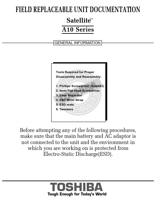
FIELD REPLACEABLE UNIT DOCUMENTATIONSatellite TMA10 Seriesnot connected to the unit and the environment in which you are working on is protected fromElectro-Static Discharge(ESD).A10 SeriesBATTERY PACK REMOVAL1. Turn the computer upside down as shown.2. Slide the battery release lever in the direction of the arrow.3. Lift out the battery pack assy .HDD REMOVAL1. Turn the computer upside down.2. Remove two M2.5x16 black flat head screws securing HDD slot cover and pull out the cover ..4. Separate the battery pack from the battery cover.OPTIONAL PC CARD REMOVAL 1. Press the eject button of the PC Card you want to remove.2. Press the extended eject button to pop the PC card out slightly.3. Grasp the PC Card and pull it outNOTE : Before removing any PCMCIA device, make sure it is “STOPPED” in the PC Card Manager.A10 SeriesBattery packBattery cover6. Remove four M3x4 brass flat head screws securing the HDD bracket to the drive.4. Slowly spread out the memory clips and pull the memory module out of the connector on a 45 degree angle.3. Remove one M2.5x5 black flat head screw securing the HDD assembly.4. Grasp the HDD bracket handle and pull to disconnect the HDD assembly.5. Lift the HDD assembly out of the HDD bay.MEMORY MODULE REMOV AL1. Turn the computer upside down.2. Remove one M2.5x4 black flat head screwsecuring the memory cover.3. Lift out the cover .A10 SeriesM2.5x5 black flat head screwHDD assyHDD bracket handleM3x4 brass flat head screwsM2.5x4 black flat head screwMemory moduleMemory clipsWIRELESS LAN CARD REMOVAL1. Turn the computer upside down.2. Remove one M2.5x4 black flat head screw securing the Mini PCI slot cover.3. Lift out the PCI slot cover .4. Peel off the glass tapesecuring the mini coax cables.5. Disconnect thewhite mini coax cable from main connector and the black mini coax cable from aux connector.6. Gently press out the Mini PCI slot clips and pull theMini PCI card out of the connector on a 30 degree angle.MODEM BOARD REMOVAL1. Remove one M2.5x4 black flat head screw securing the modem slot cover.2. Insert your finger nail or the case separator into the notched side of the cover and lift up to release the latch securing the modem slot cover.3. Remove two M2x4 black screws securing the modem board.4. Gently lift up the modem board to disconnect it from the system board and disconnect the MJ harness from JP1 on the modem board.A10 SeriesMini PCI cardPCI clipsWhite mini coax cable Black mini coax cableModem slot cover M2.5x4 black flat head screws ModemMJ Harness1. Turn the computer upside down.2. Remove two M2.5x5 black flat head screws and one M2.5x16 black flat head screw securing the modem cover.3. Remove the modem cover .COOLING MODULE REMOVALCOOLING MODULE REMOVAL1. Disconnect the fan cable fromPJ8770 on the system board.2. Remove two M2.5x5 black flat head screws securing the fan.3. Lift out the fan..2. Lift out the CPU .A10 SeriesM2.5x5 black flat head screwsCooling module brace Cooling module1. Remove M2x6 brass screws securing the cooling module brace.2. Lift out the cooling module brace .3. Lift out the cooling module .CPUClose PJ8770FanFan cable1. Open the display panel.2. Using the case separator, unlatch the keyboard holder as shown above.KEYBOARD REMOVAL3. Remove two M2.5x2.8 black flat head screwssecuring the keyboard.4. Remove one M2.5x2.8 black flat head screw securing the keyboard holder plate.5. Lift out the keyboard holder plate .6. Lift out the keyboard and set it on the palm rest.7. Remove one M2.5x8 black flat head screw securing the keyboard support plate.8. Lift out the keyboard support plate .KEYBOARD REMOVALKeyboard9. Lay the keyboard as shown above.10. Disconnect the keyboard cable from PJ3200 on the system board.11. Lift out the keyboard .A10 SeriesKeyboard holderKeyboard holder plateM2.5x4 black flat head screwM2.5x8 black flat head screwKeyboard support plateKeyboard cableA10 SeriesCD-R/W/DVD-ROM DRIVE REMOVAL1. Turn the computer upside down.2. Remove one M2.5x5 black flat head screw securing the CD-R/W/DVD-ROM drive.drive bay.5. Remove two M2x1.7 brass screws securing the CD-R/W/DVD-ROM drive bracket and lift out the bracket6. Remove one M2x3 silver screw securing the side bracket and lift out the bracket.CD-R/W/DVD-ROM drive CD-R/W/DVD-ROM DRIVE REMOVAL1. Turn the computer upside down and remove the following twenty screws:- 7 M2.5x5 black flat head screws - 13 M2.5x16 black flat head screwsCD-R/W/DVD-ROM driveM2.5x5 black flat head screw M2x1.7 brass screwsM2x3 silver screwSide bracketCD-RW/DVD drive bracketM2.5x16 black flat head screwsA10 SeriesTOP COVER REMOVAL1. Disconnect the LCD/FL cable from PJ5600 on the system board.2. Lift up the plastic insulator covering the Left/Right speaker cables and disconnect the Left/Rightspeaker cables from PJ6000/PJ6001.3. Remove one M2.5x8 black flat head screw securingtop cover and lift out the top cover assembly .TOUCH PAD ASSEMBLY REMOVAL1. Disconnect the touch pad cable from PJ3201 on the system board.2. Remove one M2.5x5 black flat head screw securingthe touch pad assembly.3. Lift out the touch pad assembly .PJ2004Touch pad assembly cableBAT CON HOLDER REMOVAL 1. Remove two M2.5x8 black flat head screw securing the bat con holder.2. Lift out the bat con holder from the system board.M2.5x8 black flat head screwsSYSTEM BOARD REMOVAL1. Peel off the glass tape securing the RTC battery cable.2. Remove two M2.5x5 black flat head screw securing the system board.3. Lift up the system boardfrom the right hand side and lift it out.A10 SeriesDC-IN JACK/RTC BATTERY REMOVAL1. Peel off the glass tape securing the DC-In jack/ RTC battery harness.2. Disconnect the DC-In jack harness from PJ8800 on the system board.3. Disconnect the RTC battery harness fromPJ8790 on the system board .RTC battery harnessDC-InJack harnessPJ8800Glass tapeFL INVERTER AND 14” LCD REMOV ALFIELD REPLACEABLE UNIT DOCUMENTATIONSatellite TMTOSHIBATough Enough for Today’s World14” DISPLAY MASK REMOVAL1. Removedisplay assembly using a pair of fine-tipped tweezers.2. Remove two M2.5x6 black flat head screws securing the display mask.3. There are 24 latches securing the display mask .Carefully insert your fingers between the mask and the LCD panel and pry open the latches starting from the bottom six latches , to the five latches on the right andleft sides , ending with the six top latches .1. Remove one M2x4 brass flat head screwsecuring the FL inverter board.2. Carefully lift up the FL inverter board anddisconnect the LCD /FL cable from CN1 and the FL cable from CN2..3. Remove four mask seals to expose four screws securing the LCD module assembly.4. Remove four M2X4 brass flat head screws securing the LCD module assembly.5. Carefully rotate out the top of the LCD module enough to access the display cable.6. Peel off the tape securing the LCD/FL cable and disconnect the cable.7. Remove four M2x3 silver flat head screws securing the left/right LCD brackets.A10 SeriesLatch。
计算机硬件维修手册

计算机硬件维修手册电脑出现的故障原因扑朔迷离,让人难以捉摸。
并且由于Windows操作系统的组件相对复杂,电脑一旦出现故障,对于普通用户来说,想要准确地找出其故障的原因几乎是不可能的。
那么是否是说我们如果遇到电脑故障的时候,就完全束手无策了呢?其实并非如此,使电脑产生故障的原因虽然有很多,但是,只要我们细心观察,认真总结,我们还是可以掌握一些电脑故障的规律和处理办法的。
在本期的小册子中,我们就将一些最为常见也是最为典型的电脑故障的诊断、维护方法展示给你,通过它,你就会发现——解决电脑故障方法就在你的身边,简单,但有效!电脑是由各种配件组合而成的,下面,我们就根据组成电脑的各个部件分别对其经常出现的故障进行分析。
计算机硬件维修手册(主板篇)主板是整个电脑的关键部件,在电脑起着至关重要的作用。
如果主板产生故障将会影响到整个PC机系统的工作。
下面,我们就一起来看看主板在使用过程中最常见的故障有哪些。
常见故障一:开机无显示电脑开机无显示,首先我们要检查的就是是BIOS。
主板的BIOS中储存着重要的硬件数据,同时BIOS也是主板中比较脆弱的部分,极易受到破坏,一旦受损就会导致系统无法运行,出现此类故障一般是因为主板BIOS被CIH病毒破坏造成(当然也不排除主板本身故障导致系统无法运行。
)。
一般BIOS被病毒破坏后硬盘里的数据将全部丢失,所以我们可以通过检测硬盘数据是否完好来判断BIOS是否被破坏,如果硬盘数据完好无损,那么还有三种原因会造成开机无显示的现象:1. 因为主板扩展槽或扩展卡有问题,导致插上诸如声卡等扩展卡后主板没有响应而无显示。
2. 免跳线主板在CMOS里设置的CPU频率不对,也可能会引发不显示故障,对此,只要清除CMOS即可予以解决。
清除CMOS的跳线一般在主板的锂电池附近,其默认位置一般为1、2短路,只要将其改跳为2、3短路几秒种即可解决问题,对于以前的老主板如若用户找不到该跳线,只要将电池取下,待开机显示进入CMOS设置后再关机,将电池上上去亦达到CMOS 放电之目的。
电脑维修教材(新版)
2.2.7 静电系数
2020/9/29
Typical Triboelectric Series + Air
Positive Hands Glass Hair Quartz Nylon Wool Silk Lead Aluminu m Paper Cotton Steel Wood Nickel Copper Rubber Gold Polyester Polyethyle ne
9. 开关电源-------------------------------------------------------------------------------------------- 172
10. SFT程式简介------------------------------------------------------------------------------------- 203
Typical Facility Areas Requiring ESD Protection 需靜電保護設備的區域
Receiving 接受 Inspection 檢驗室 Stores and warehouses 倉庫 Assembly 裝配線 Test and inspection 測試房 Research and development 研發部 Packaging 包裝線 Field service repair 場服務需要 Offices and laboratories 辦公室和實驗室 SMT rooms SMT 房
3)只有底面焊點之零件偏移大于端末寬度的1/2或焊點寬度的1/2,取較小者﹒
4)圓形及扁圓形引腳,偏移大于扁圓引腳寬度或圓腳直徑的1/2
东芝笔记本故障怎么维修

东芝笔记本故障怎么维修推荐文章笔记本怎么提高性能热度:笔记本怎么解除WiFi密码热度:惠普笔记本无线网卡驱动异常怎么办热度:惠普笔记本怎么样热度:笔记本电脑键盘灯在哪里怎么打开热度:在我们面对着一年春夏秋冬的四个季节里面,由于我们的东芝笔记本需要适应各个气候所造成的影响,所以在每个季节当中,我们都需要对我们的东芝笔记本进行适当的维修与检测。
这样,东芝笔记本的散热器才能适应环境得以更长久健康地运行,然后我们东芝笔记本的寿命才能更长。
希望大家能从店铺给大家推荐的文章当中,确确实实能学到修复东芝笔记本的方法。
1.东芝笔记本开机不亮类故障故障现象:开机不亮故障就是能开机,但不能点亮显示屏。
按下开机键的时候,电源指示灯和硬盘指示灯亮了,CPU风扇也转动了,也能正常开关机,但外接显示器不显示。
故障部位:发生开机不亮故障时主供电和系统供电电路基本正常,主要是信号系统出现故障。
这里需要指出,信号系统不是纯粹的软件系统,信号系统包括BIOS、总线、控制信号、时钟信号等,信号不正常是由于硬件错误引起的。
解决措施:这种故障涉及的面很广,CPU、南桥、北桥、时钟电路、BIOS和显示电路均会造成此类故障,可以采取以下办法维修:(1)利用可调电源,根据电流值初步判断故障的范围。
(2)利用主板诊断卡,根据故障代码和指示灯确定故障部位。
(3)用万用表测量关键信号,包括BIOS、总线、控制信号、时钟信号等,判斯故障范围。
易损元件:时钟电路,造成时钟信号不正常。
复位电路,造成复位信号不正常。
CPU工作电路中条件不具备,造成开机不亮故障。
2.东芝笔记本不开机类故障故障现象:不开机是指笔记本电脑不能加电,即按下开机键,笔记本电脑没有任何开机现象,如电源指示灯和硬盘指示灯不亮,CPU 风扇也不转,就如同没有按下开机键一样。
故障原因:不开机故障是由于供电电路出现故障,或者负载有严重短路,也可能是与开机有关的其他电路出现问题。
解决措施:在维修的时候首先要排除短路的情况。
电脑维修指导手册

电脑维修指导手册目录第一部分总则第一章电脑维修的基本原则和方法第二章电脑维修步骤与维修操作注意事项第二部分常见故障判断第一章加电类故障第二章启动与关闭类故障第三章磁盘类故障第四章显示类故障第五章安装类故障第六章操作与应用类故障第七章局域网类故障第八章Internet 类故障第九章端口与外设故障第十章音视频类故障第十一章兼容类故障第三部分附录附录一故障处理流程之一加电类故障处理流程之二启动与关闭类故障处理流程之三磁盘类故障处理流程之四显示类故障处理流程之五安装类故障处理流程之七局域网类故障处理流程之八Internet 类故障处理流程之九端口与外设故障处理流程之十音视频类故障处理流程附录二部分部件、设备的技术规格之一内存技术规格识别之二显示器技术规格之三Windows 98SE 关机问题前言本手册共分三大部分。
第一部分阐述了维修的一般方法,维修的原则及维修中应注意的问题。
这一部分是整个手册的关键部分,只有理解并掌握其中的观点、方法后,才可能理解和应用第二部分的内容。
第二部分从故障现象入手,通过对故障现象分类,进而对每一类故障的分析、判断提供一种思路或方法。
附录一中的故障判断流程是对相关故障类的补充,试图对刚从事维修工作的工程师提出一个入手的方法。
最后一部分是附录。
在附录中除故障判断流程外,还包含一些部件的技术规格和标准,以便工程师在维修中参考。
1第一部分总则本部分主要介绍维修的基本原则、方法,和维修的过程、在维修中应注意的问题。
在最后,为了能方便地使用第二部分的内容,提供了基本的维修判断的思路。
第一章电脑维修的基本原则和方法电话判断的基本原则和方法上门服务前的准备z 电话判断z 准备备件这里所述原则、方法等是第二部分分类判断的基础,需要认真遵守执行。
§1.1 进行电脑维修应遵循的基本原则:一、进行维修判断须从最简单的事情做起简单的事情,一方面指观察,另一方面是指简捷的环境。
简单的事情就是观察,它包括:1、电脑周围的环境情况——位置、电源、连接、其它设备、温度与湿度等;2、电脑所表现的现象、显示的内容,及它们与正常情况下的异同;3、电脑内部的环境情况——灰尘、连接、器件的颜色、部件的形状、指示灯的状态等;4、电脑的软硬件配置——安装了何种硬件,资源的使用情况;使用的是使种操作系统,其上又安装了何种应用软件;硬件的设置驱动程序版本等。
- 1、下载文档前请自行甄别文档内容的完整性,平台不提供额外的编辑、内容补充、找答案等附加服务。
- 2、"仅部分预览"的文档,不可在线预览部分如存在完整性等问题,可反馈申请退款(可完整预览的文档不适用该条件!)。
- 3、如文档侵犯您的权益,请联系客服反馈,我们会尽快为您处理(人工客服工作时间:9:00-18:30)。
FIELD REPLACEABLE UNIT DOCUMENTATIONTecra TMnot connected to the unit and the environment in which you are working on is protected fromElectro-Static Discharge(ESD).A1 SeriesBATTERY PACK REMOVAL1. Turn the computer upside down as shown.2. Slide the battery release lever in the direction of the arrow.3. Lift out the battery pack assy .HDD REMOVAL1. Turn the computer upside down.2. Remove two M2.5x16 black flat head screws securing HDD slot cover and pull out the cover ..4. Separate the battery pack from the battery cover.OPTIONAL PC CARD REMOVAL 1. Press the eject button of the PC Card you want to remove.2. Press the extended eject button to pop the PC card out slightly.3. Grasp the PC Card and pull it outNOTE: Before removing any PCMCIA device, make sure it is “STOPPED” in the PC Card Manager.Battery packBattery cover A1 Series6. Remove four M3x4 brass flat head screws securing the HDD bracket to the drive.4. Slowly spread out the memory clips and pull the memory module out of the connector on a 45 degree angle.3. Remove one M2.5x5 black flat head screw securing the HDD assembly.4. Grasp the HDD bracket handle and pull to disconnect the HDD assembly.5. Lift the HDD assembly out of the HDD bay.MEMORY MODULE REMOVAL1. Turn the computer upside down.2. Remove one M2.5x4 black flat head screwsecuring the memory cover.3. Lift out thecover .M2.5x5 black flat head screwHDD assyHDD bracket handleM3x4 brass flat head screwsM2.5x4 black flat head screwMemory moduleMemory clipsA1 SeriesWIRELESS LAN CARD REMOVAL1. Turn the computer upside down.2. Remove one M2.5x4 black flat head screw securing the Mini PCI slot cover.3. Lift out the PCI slot cover .4. Peel off the glass tape securing the mini coax cables.5. Disconnect the white mini coax cable from main connector and the black mini coax cable from aux connector.6. Gently press out the Mini PCI slot clips and pull the Mini PCI card out of the connector on a 30 degree angle.MODEM BOARD REMOVAL1. Remove one M2.5x4 black flat head screw securing the modem slot cover.2. Insert your finger nail or the case separator into the notched side of the cover and lift up to release the latch securing the modem slot cover.3. Remove two M2x4 black screws securing the modem board.4. Gently lift up the modem board to disconnect it fromthe system board and disconnect the MJ harnessfrom JP1 on the modem board.Mini PCI cardPCI clipsWhite mini coax cableBlack mini coax cableModem slot cover M2.5x4 black flat head screws ModemMJ Harness M1 Series1. Turn the computer upside down.2. Remove two M2.5x5 black flat head screws and one M2.5x16 black flat head screw securing the modem cover.3. Remove the modem cover .COOLING MODULE REMOVALCOOLING MODULE REMOVAL1. Disconnect the fan cable from PJ8770 on the system board.2. Remove two M2.5x5 black flat head screws securing the fan.3. Lift out thefan ..2. Lift out the CPU .M2.5x5 black flat head screwsCooling module brace Cooling module1. Remove M2x6 brass screws securing the cooling module brace.2. Lift out the cooling module brace .3. Lift out the cooling module .CPUClose PJ8770FanFan cableA1 Series1. Open the display panel.2. Using the case separator, unlatch the keyboard holder as shown above.KEYBOARD REMOVAL3. Remove two M2.5x2.8 black flat head screws securing the keyboard.4. Remove one M2.5x2.8 black flat head screw securing the keyboard holder plate.5. Lift out the keyboard holder plate .6. Lift out the keyboard and set it on the palm rest.7. Remove one M2.5x8 black flat head screw securing the keyboard support plate.8. Lift out the keyboard support plate .KEYBOARD REMOVALKeyboard9. Lay the keyboard as shown above.10. Disconnect the keyboard cable from PJ3200 on the system board.11. Lift out the keyboard .Keyboard holderKeyboard holderplateM2.5x4 black flat head screwM2.5x8 black flat head screwKeyboard support plateKeyboard cableA1 SeriesCD-R/W/DVD-ROM DRIVE REMOVAL1. Turn the computer upside down.2. Remove one M2.5x5 black flat head screw securing the CD-R/W/DVD-ROM drive.drive bay.5. Remove two M2x1.7 brass screws securing the CD-R/W/DVD-ROM drive bracket and lift out the bracket6. Remove one M2x3 silver screw securing the side bracket and lift out the bracket.CD-R/W/DVD-ROM drive CD-R/W/DVD-ROM DRIVE REMOVAL1. Turn the computer upside down and remove the following twenty screws:- 7 M2.5x5 black flat head screws - 13 M2.5x16 black flat head screwsCD-R/W/DVD-ROM driveM2.5x5 black flat head screw M2x1.7 brass screwsM2x3 silver screwSide bracketCD-RW/DVD drive bracketM2.5x16 black flat head screwsA1 SeriesTOP COVER REMOVAL1. Disconnect the LCD/FL cable from PJ5600 on the system board.2. Lift up the plastic insulator covering the Left/Right speaker cables and disconnect the Left/Rightspeaker cables from PJ6000/PJ6001.3. Remove one M2.5x8 black flat head screw securing top cover and lift out the top cover assembly.TOUCH PAD ASSEMBL Y REMOVAL1. Disconnect the touch pad cable from PJ3201 on the system board.2. Remove one M2.5x5 black flat head screwsecuring the touch pad assembly.3. Lift out the touch pad assembly .PJ2004Touch pad assemblycableBAT CON HOLDER REMOVAL 1. Remove two M2.5x8 black flat head screw securing the bat con holder.2. Lift out the bat con holder from the system board.M2.5x8 black flat head screwsSYSTEM BOARD REMOVAL1. Peel off the glass tape securing the RTC battery cable.2. Remove two M2.5x5 black flat head screw securing the system board.3. Lift up the system boardfrom the right hand sideand lift it out.A1 SeriesDC-IN JACK/RTC BATTERY REMOVAL1. Peel off the glass tape securing the DC-In jack/ RTC battery harness.2. Disconnect the DC-In jack harness from PJ8800 on the system board.3. Disconnect the RTC battery harness fromPJ8790 on the system board .RTC battery harnessDC-InJack harnessPJ8800Glass tapeA1 SeriesFL INVERTER AND 14” LCD REMOV ALFIELD REPLACEABLE UNIT DOCUMENTATIONTOSHIBATough Enough for Today’s World14” DISPLAY MASK REMOVAL1. Removedisplay assembly using a pair of fine-tipped tweezers.2. Remove two M2.5x6 black flat head screws securing the display mask.3. There are 24 latches securing the display mask .Carefully insert your fingers between the mask and the LCD panel and pry open the latches starting from the bottom six latches , to the five latches on the right andleft sides , ending with the six top latches .1. Remove one M2x4 brass flat head screwsecuring the FL inverter board.2. Carefully lift up the FL inverter board anddisconnect the LCD /FL cable from CN1 and the FL cable from CN2..3. Remove four mask seals to expose four screws securing the LCD module assembly.4. Remove four M2X4 brass flat head screws securing the LCD module assembly.5. Carefully rotate out the top of the LCD module enough to access the display cable.6. Peel off the tape securing the LCD/FL cable and disconnect the cable.7. Remove four M2x3 silver flat head screws securing the left/right LCD brackets.LatchTecra TMA1 Series。