FU-68PDF-520M93B中文资料
FU-68SDF-V910M47F资料

1.55 μm DFB-LD MODULE WITH SINGLEMODE FIBER PIGTAILDESCRIPTIONModule type FU-68SDF-x902MzzF/-x910MzzF is a1.55μm DFB-LD module with single mode optical fiber. This module is suitable to a directly modulated light source for use in2.5Gb/s digital optical communication systems.This module is prepared in accordance with ITU-T recommendation wavelength channel plan for Dense-WDM transmission.FEATURES• • I nput impedance is 25Ω• Multi quantum wells (MQW) DFB Laser Diode module• Emission wavelength is in full C band • Single mode optical fiber pig-tail • Built-in optical isolator• Built-in thermal electric cooler • Butterfly package• With photodiode for optical output monitor • RoHS (2002/95/EC) complian tAPPLICATIONHigh speed transmission systems (~2.5Gb/s) Dense-WDM systemsABSOLUTE MAXIMUM RATINGS (Tld=Tset)Parameter Symbol Conditions RatingUnit-x902MzzF 6 Optical output power Pf CW -x910MzzF 15mW Forward current If CW 150 mA Laser diode Reverse voltage Vrl - 2 VReverse voltage Vrd - 20 VPhotodiode Forward current Ifd - 2 mACooler current Ipe - 1.3 A Thermo-electric cooler (Note 1) Cooler voltage Vpe - 3.1 V Operating case temperature Tc - -20 ~ 70 °C Storage temperature Tstg - -40 ~ 85 °CNote 1) Even if the thermo-electric cooler (TEC) is operated within the rated conditions, uncontrolled current loading oroperation without heatsink may easily damage the module by exceeding the storage temperature range.Thermistor resistance should be properly monitored by the feedback circuit during TEC operation to avoid the catastrophic damage.1.55 μm DFB-LD MODULE WITH SINGLEMODE FIBER PIGTAILELECTRICAL/OPTICAL CHARACTERISTICS (Tld=Tset, Tc=25°C unless otherwise noted)LimitsParameter Symbol Test Conditions Min. Typ. Max.Unit -x902MzzF 2 Optical output P 0 CW,If=Iop -x910MzzF 10mWThreshold current Ith CW - 10 25 mA -x902MzzF - - 100 Optical output power at threshold current Pth CW, If=Ith -x910MzzF - - 150μW -x902MzzF - 40 65Operating current Iop CW, Pf=P 0 -x910MzzF - 50 95mA Operating voltage Vop CW, Pf=P 0 - 1.3 1.8 V Input impedance Zin Pf= P 0 - 25 - Ω Light-emission central wavelength λc (Note 2) See Ordering Information and Table 1 nm Central wavelength drift with case temp.Δλc/ΔTc Tc=-20~70°C -1 - 0 pm/°C Laser operating temperature Tset - 20 - 35 °C Spectral width Δλ (Note 2), -20dB - 0.2 0.4 nm Side mode suppression ratio Sr (Note 2) 33 40 - dBDispersion penalty Pp (Note 2), at 10-10BER, +3000ps/nm- - 2 dBCutoff frequency (-1.5dB optical)fc Pf= P 0 3.5 - - GHz Rise and fall time (10~90%) tr, tf (Note 2) - - 150 psec Relative intensity noise Nr CW, Pf= P 0, f =0.5~3GHz - -155 -145 dB/HzTracking error Er Tc=-20~70°C, APC, ATC(Note 3) - - 0.5 dB -x902MzzF 0.0570.07 0.15 Differential efficiency ηCW Pf= P 0 -x910MzzF 0.15 0.25 0.35 mW/m A LinearityΔηCW, Pf= P 0 x0.1~ P 0x1.2 (Note 4)-20 - 20 % -x902MzzF 0.1 - 2 Monitor current Imon CW, Pf= P 0 Vrd=5V -x910MzzF 0.2 - 3mATc=25°C 35 - - Optical isolation Iso Tc=-20~70°C23 - - dBDark current (PD) Id Vrd=5V, Tc=-20~70°C - - 0.1 μA Capacitance (PD) Ct Vrd=5V, f=1MHz - - 10 pFNote 2) 2.48832Gb/s NRZ, 223-1, Pf_ave= P 0 x 0.5, Extinction ratio 10dB, optical return loss of the connectors should begreater than 40dB in order to ensure the specified performance.Note 3) Er=max|10×log(Pf / Pf@25°C)|Note 4) Variation of the differential efficiency from the straight line between P 0 x0.1~ P 0x1.2THERMAL CHARACTERISTICS (Tld=Tset, Tc=-20~70°C)Parameter Symbol Test Conditions Limits Unit Min.Typ. Max. Thermistor resistance Rth Tld=25°C 9.5 10 10.5 k Ω B constant of Rth B - - 3950 - K Cooling capacity ΔT Pf= P 0, Tc=70°C 50 - - °C Cooler current Ipe Pf= P 0, Tc=70°C, Tld=Tset - 0.6 1 A Cooler voltage Vpe Pf= P 0, Tc=70°C, Tld=Tset - 1.2 2 V1.55 μm DFB-LD MODULE WITH SINGLEMODE FIBER PIGTAILFIBER PIGTAIL SPECIFICATIONSUnitParameter Limits- Type SMMode field diameter 9.5+/-1 μmCladding diameter 125+/-2 μmmmSecondary coating outer diameter 0.9+/-0.1Connector (Note 5) -Optical return loss of connector 40 (min) dBNote 5) SC/PC and FC/PC are available. Other connectors are also available for large quantities.DOCUMENTATION (Tld=Tset)•Fiber output power vs. Laser forward current at Tld=Tset and Tc=25°C•Threshold current (Ith)•Laser forward current (Iop) at Pf=P0•Laser forward voltage (Vop) at Pf= P0•Laser operating temperature (Tset) at λc (Note 6)•Monitor current (Imon) at Pf= P0•Thermistor resistance (Rth)•Cooler current (Ipe) at Pf= P0 and Tc=70°C•Cooler voltage (Vpe) at Pf= P0 and Tc=70°CNote 6) Tset is attached as a reference data. Rth should be used in order to tune the wavelength to the specified value accurately.1.55 μm DFB-LD MODULE WITH SINGLEMODE FIBER PIGTAIL ORDERING INFORMATIONFU - 68SDF – _ 9 _ _ M __ Fλ code See table 1Peak Output Power02 2mW10 10mWConnectorW SC/PCV FC/PCTable 1.f [THz] λc [nm] λ code f [THz]λc [nm] λ code196.30 1527.22 3 192.801554.9473196.20 1527.99 5 192.701555.7575196.10 1528.777 192.601556.5577196.00 1529.559 192.501557.3679195.90 1530.3311 192.401558.1781195.80 1531.1213 192.301558.9883195.70 1531.9015 192.201559.7985195.60 1532.6817 192.101560.6187195.50 1533.4719 192.001561.4289195.40 1534.2521 191.901562.2391195.30 1535.0423 191.801563.0593195.20 1535.8225 191.701563.8695195.10 1536.6127195.00 1537.4029194.90 1538.1931194.80 1538.9833194.70 1539.7735194.60 1540.5637194.50 1541.3539194.40 1542.1441194.30 1542.9443194.20 1543.7345194.10 1544.5347194.00 1545.3249193.90 1546.1251193.80 1546.9253193.70 1547.7255193.60 1548.5157193.50 1549.3259193.40 1550.1261193.30 1550.9263193.20 1551.7265193.10 1552.5267193.00 1553.3369192.90 1554.1371All wavelengths are referred to vacuum. Tolerance is λc+/-0.05nm.1.55 μm DFB-LD MODULE WITH SINGLEMODE FIBER PIGTAILOUTLINE DIAGRAMUnless otherwise noted +/-0.5mm(Unit : mm)FU-68SDF-x9yyMzzF1.55 μm DFB-LD MODULE WITH SINGLEMODE FIBER PIGTAIL Safety Cautions for Use of Optoelectronic DevicesGeneral:Although the manufacturer is always striving to improve the reliability of its product, problems and errors may occur with semiconductor products. Therefore, the user's products are required to be designed with full safety regard to prevent any accidents that results in injury, death, fire or environmental damage even when semiconductor products happen to error. Especially it is recommended to take in consideration about redundancy, fire prevention, error prevention safeguards. And the following requirements must be strictly observed.Warning!1. Eye safety : Seminductor laser radiates laser light during operation. Laser light is very dangerous when shot directly into human eyes. Don't look at laser light directly, or through optics such as a lens. The laser light should be observed using the ITV camera, IR-viewer, or other appropriate instruments.2. Product handling : The product contains GaAs (gallium arsenide). It is safe for regular use, but harmful to the human body if made into powder or steam. Be sure to avoid dangerous process like smashing, burning, chemical etching. Never put this product in one's mouth or swallow it.3. Product disposal : This product must be disposed of as special industrial waste. It is necessary to separate it from general industrial waste and general garbage.Handling Cautions for Optoelectronic Devices1. General:(1) The products described in this specification are designed and manufactured for use in general communication systems or electronic devices, unless their applications or reliability are otherwise specified. Therefore, they are not designed or manufactured for installation in devices or systems that may affect human life or that are used in social infrastructure requiring high reliability.(2) When the customer is considering to use the products in special applications, such as transportation systems (automobiles, trains, vessels), medical equipments, aerospace, nuclear power control, and submarine repeaters or systems, please contact Mitsubishi Electric or an authorized distributor.2. Shipping Conditions:(1) During shipment, place the packing boxes in the correct direction, and fix them firmly to keep them immovable. Placing the boxes upside down, tilting, or applying abnormal pressure onto them may cause deformation in the electrode terminals, breaking of optical fiber, or other problems.(2) Never throw or drop the packing boxes. Hard impact on the boxes may cause break of the devices.(3) Take strict precautions to keep the devices dry when shipping under rain or snow.3. Storage Conditions:When storing the products, it is recommended to store them following the conditions described below without opening the packing. Not taking enough care in storing may result in defects in electrical characteristics, soldering quality, visual appearance, and so on. The main points are described below (if special storage conditions are given to the product in the specification sheet, they have priority over the following general cautions):(1) Appropriate temperature and humidity conditions, i.e., temperature range between 5~30°C, and humidity between 40~60 percent RH, should be maintained in storage locations. Controlling the temperature and humidity within this range is particularly important in case of long-term storage for six months or more.(2) The atmosphere should be particularly free from toxic gases and dust.(3) Do not apply any load on the product.(4) Do not cut or bend the leads of the devices which are to be stored. This is to prevent corrosion in the cut or bent part of the lead causing soldering problems in the customer’s assembling process.(5) Sudden change in temperature may cause condensation in the product or packing, therefore, such locations should be avoided for storing. Temperature in storage locations should be stable.(6) When storing ceramic package products for extended periods of time, the leads may turn reddish due to reaction with sulfur in the atmosphere.(7) Storage conditions for bare chip and unsealed products shall be stated separately because bare chip and unsealed products require stricter controls than package sealed products.4. Design Conditions and Environment under Use:(1) Avoid use in locations where water or organic solvents adhere directly to the product, or where there is any possibility of the generation of corrosive gas, explosive gas, dust, salinity, or other troublesome conditions. Such environments will not only significantly lower the reliability, but also may lead to serious accidents.(2) Operation in excess of the absolute maximum ratings can cause permanent damage to the device. The customers are requested to design not to exceed those ratings even for a short time.5. ESD Safety Cautions:The optoelectronic devices are sensitive to static electricity (ESD, electro-static discharge). The product can be broken by ESD. When handling this product, please observe the following countermeasures:<Countermeasures against Static Electricity and Surge>To prevent break of devices by static electricity or surge, please adopt the following countermeasures in the assembly line:(1) Ground all equipments, machinery jigs, and tools in the process line with earth wires installed in them. Take particular care with hot plates, solder irons and other items for which the commercial power supplies are prone to leakage.(2) Workers should always use earth bands. Use of antistatic clothing, electric conductive shoes, and other safety equipment while at work is highly recommended.(3) Use conductive materials for this product’s container, etc.(4) It is recommended that grounding mats be placed on the surfaces of assembly line workbench and the surrounding floor in work area, etc.(5) When mounting this product in parts or materials which can be electrically charged (printed wiring boards, plastic products, etc.), pay close attention to the static electricity in those parts. ESD may damage the product.(6) Humidity in working environment should be controlled to be 40 percent RH or higher.These countermeasures are most general, and there is a need to carefully confirm the line before starting mass production using this product (in the trial production, etc.). It is extremely important to prevent surge, eliminate it rapidly, and prevent it from spreading.。
FU-68SDF-V910M95F中文资料

1.55 μm DFB-LD MODULE WITH SINGLEMODE FIBER PIGTAILDESCRIPTIONModule type FU-68SDF-x902MzzF/-x910MzzF is a1.55μm DFB-LD module with single mode optical fiber. This module is suitable to a directly modulated light source for use in2.5Gb/s digital optical communication systems.This module is prepared in accordance with ITU-T recommendation wavelength channel plan for Dense-WDM transmission.FEATURES• • I nput impedance is 25Ω• Multi quantum wells (MQW) DFB Laser Diode module• Emission wavelength is in full C band • Single mode optical fiber pig-tail • Built-in optical isolator• Built-in thermal electric cooler • Butterfly package• With photodiode for optical output monitor • RoHS (2002/95/EC) complian tAPPLICATIONHigh speed transmission systems (~2.5Gb/s) Dense-WDM systemsABSOLUTE MAXIMUM RATINGS (Tld=Tset)Parameter Symbol Conditions RatingUnit-x902MzzF 6 Optical output power Pf CW -x910MzzF 15mW Forward current If CW 150 mA Laser diode Reverse voltage Vrl - 2 VReverse voltage Vrd - 20 VPhotodiode Forward current Ifd - 2 mACooler current Ipe - 1.3 A Thermo-electric cooler (Note 1) Cooler voltage Vpe - 3.1 V Operating case temperature Tc - -20 ~ 70 °C Storage temperature Tstg - -40 ~ 85 °CNote 1) Even if the thermo-electric cooler (TEC) is operated within the rated conditions, uncontrolled current loading oroperation without heatsink may easily damage the module by exceeding the storage temperature range.Thermistor resistance should be properly monitored by the feedback circuit during TEC operation to avoid the catastrophic damage.1.55 μm DFB-LD MODULE WITH SINGLEMODE FIBER PIGTAILELECTRICAL/OPTICAL CHARACTERISTICS (Tld=Tset, Tc=25°C unless otherwise noted)LimitsParameter Symbol Test Conditions Min. Typ. Max.Unit -x902MzzF 2 Optical output P 0 CW,If=Iop -x910MzzF 10mWThreshold current Ith CW - 10 25 mA -x902MzzF - - 100 Optical output power at threshold current Pth CW, If=Ith -x910MzzF - - 150μW -x902MzzF - 40 65Operating current Iop CW, Pf=P 0 -x910MzzF - 50 95mA Operating voltage Vop CW, Pf=P 0 - 1.3 1.8 V Input impedance Zin Pf= P 0 - 25 - Ω Light-emission central wavelength λc (Note 2) See Ordering Information and Table 1 nm Central wavelength drift with case temp.Δλc/ΔTc Tc=-20~70°C -1 - 0 pm/°C Laser operating temperature Tset - 20 - 35 °C Spectral width Δλ (Note 2), -20dB - 0.2 0.4 nm Side mode suppression ratio Sr (Note 2) 33 40 - dBDispersion penalty Pp (Note 2), at 10-10BER, +3000ps/nm- - 2 dBCutoff frequency (-1.5dB optical)fc Pf= P 0 3.5 - - GHz Rise and fall time (10~90%) tr, tf (Note 2) - - 150 psec Relative intensity noise Nr CW, Pf= P 0, f =0.5~3GHz - -155 -145 dB/HzTracking error Er Tc=-20~70°C, APC, ATC(Note 3) - - 0.5 dB -x902MzzF 0.0570.07 0.15 Differential efficiency ηCW Pf= P 0 -x910MzzF 0.15 0.25 0.35 mW/m A LinearityΔηCW, Pf= P 0 x0.1~ P 0x1.2 (Note 4)-20 - 20 % -x902MzzF 0.1 - 2 Monitor current Imon CW, Pf= P 0 Vrd=5V -x910MzzF 0.2 - 3mATc=25°C 35 - - Optical isolation Iso Tc=-20~70°C23 - - dBDark current (PD) Id Vrd=5V, Tc=-20~70°C - - 0.1 μA Capacitance (PD) Ct Vrd=5V, f=1MHz - - 10 pFNote 2) 2.48832Gb/s NRZ, 223-1, Pf_ave= P 0 x 0.5, Extinction ratio 10dB, optical return loss of the connectors should begreater than 40dB in order to ensure the specified performance.Note 3) Er=max|10×log(Pf / Pf@25°C)|Note 4) Variation of the differential efficiency from the straight line between P 0 x0.1~ P 0x1.2THERMAL CHARACTERISTICS (Tld=Tset, Tc=-20~70°C)Parameter Symbol Test Conditions Limits Unit Min.Typ. Max. Thermistor resistance Rth Tld=25°C 9.5 10 10.5 k Ω B constant of Rth B - - 3950 - K Cooling capacity ΔT Pf= P 0, Tc=70°C 50 - - °C Cooler current Ipe Pf= P 0, Tc=70°C, Tld=Tset - 0.6 1 A Cooler voltage Vpe Pf= P 0, Tc=70°C, Tld=Tset - 1.2 2 V1.55 μm DFB-LD MODULE WITH SINGLEMODE FIBER PIGTAILFIBER PIGTAIL SPECIFICATIONSUnitParameter Limits- Type SMMode field diameter 9.5+/-1 μmCladding diameter 125+/-2 μmmmSecondary coating outer diameter 0.9+/-0.1Connector (Note 5) -Optical return loss of connector 40 (min) dBNote 5) SC/PC and FC/PC are available. Other connectors are also available for large quantities.DOCUMENTATION (Tld=Tset)•Fiber output power vs. Laser forward current at Tld=Tset and Tc=25°C•Threshold current (Ith)•Laser forward current (Iop) at Pf=P0•Laser forward voltage (Vop) at Pf= P0•Laser operating temperature (Tset) at λc (Note 6)•Monitor current (Imon) at Pf= P0•Thermistor resistance (Rth)•Cooler current (Ipe) at Pf= P0 and Tc=70°C•Cooler voltage (Vpe) at Pf= P0 and Tc=70°CNote 6) Tset is attached as a reference data. Rth should be used in order to tune the wavelength to the specified value accurately.1.55 μm DFB-LD MODULE WITH SINGLEMODE FIBER PIGTAIL ORDERING INFORMATIONFU - 68SDF – _ 9 _ _ M __ Fλ code See table 1Peak Output Power02 2mW10 10mWConnectorW SC/PCV FC/PCTable 1.f [THz] λc [nm] λ code f [THz]λc [nm] λ code196.30 1527.22 3 192.801554.9473196.20 1527.99 5 192.701555.7575196.10 1528.777 192.601556.5577196.00 1529.559 192.501557.3679195.90 1530.3311 192.401558.1781195.80 1531.1213 192.301558.9883195.70 1531.9015 192.201559.7985195.60 1532.6817 192.101560.6187195.50 1533.4719 192.001561.4289195.40 1534.2521 191.901562.2391195.30 1535.0423 191.801563.0593195.20 1535.8225 191.701563.8695195.10 1536.6127195.00 1537.4029194.90 1538.1931194.80 1538.9833194.70 1539.7735194.60 1540.5637194.50 1541.3539194.40 1542.1441194.30 1542.9443194.20 1543.7345194.10 1544.5347194.00 1545.3249193.90 1546.1251193.80 1546.9253193.70 1547.7255193.60 1548.5157193.50 1549.3259193.40 1550.1261193.30 1550.9263193.20 1551.7265193.10 1552.5267193.00 1553.3369192.90 1554.1371All wavelengths are referred to vacuum. Tolerance is λc+/-0.05nm.1.55 μm DFB-LD MODULE WITH SINGLEMODE FIBER PIGTAILOUTLINE DIAGRAMUnless otherwise noted +/-0.5mm(Unit : mm)FU-68SDF-x9yyMzzF1.55 μm DFB-LD MODULE WITH SINGLEMODE FIBER PIGTAIL Safety Cautions for Use of Optoelectronic DevicesGeneral:Although the manufacturer is always striving to improve the reliability of its product, problems and errors may occur with semiconductor products. Therefore, the user's products are required to be designed with full safety regard to prevent any accidents that results in injury, death, fire or environmental damage even when semiconductor products happen to error. Especially it is recommended to take in consideration about redundancy, fire prevention, error prevention safeguards. And the following requirements must be strictly observed.Warning!1. Eye safety : Seminductor laser radiates laser light during operation. Laser light is very dangerous when shot directly into human eyes. Don't look at laser light directly, or through optics such as a lens. The laser light should be observed using the ITV camera, IR-viewer, or other appropriate instruments.2. Product handling : The product contains GaAs (gallium arsenide). It is safe for regular use, but harmful to the human body if made into powder or steam. Be sure to avoid dangerous process like smashing, burning, chemical etching. Never put this product in one's mouth or swallow it.3. Product disposal : This product must be disposed of as special industrial waste. It is necessary to separate it from general industrial waste and general garbage.Handling Cautions for Optoelectronic Devices1. General:(1) The products described in this specification are designed and manufactured for use in general communication systems or electronic devices, unless their applications or reliability are otherwise specified. Therefore, they are not designed or manufactured for installation in devices or systems that may affect human life or that are used in social infrastructure requiring high reliability.(2) When the customer is considering to use the products in special applications, such as transportation systems (automobiles, trains, vessels), medical equipments, aerospace, nuclear power control, and submarine repeaters or systems, please contact Mitsubishi Electric or an authorized distributor.2. Shipping Conditions:(1) During shipment, place the packing boxes in the correct direction, and fix them firmly to keep them immovable. Placing the boxes upside down, tilting, or applying abnormal pressure onto them may cause deformation in the electrode terminals, breaking of optical fiber, or other problems.(2) Never throw or drop the packing boxes. Hard impact on the boxes may cause break of the devices.(3) Take strict precautions to keep the devices dry when shipping under rain or snow.3. Storage Conditions:When storing the products, it is recommended to store them following the conditions described below without opening the packing. Not taking enough care in storing may result in defects in electrical characteristics, soldering quality, visual appearance, and so on. The main points are described below (if special storage conditions are given to the product in the specification sheet, they have priority over the following general cautions):(1) Appropriate temperature and humidity conditions, i.e., temperature range between 5~30°C, and humidity between 40~60 percent RH, should be maintained in storage locations. Controlling the temperature and humidity within this range is particularly important in case of long-term storage for six months or more.(2) The atmosphere should be particularly free from toxic gases and dust.(3) Do not apply any load on the product.(4) Do not cut or bend the leads of the devices which are to be stored. This is to prevent corrosion in the cut or bent part of the lead causing soldering problems in the customer’s assembling process.(5) Sudden change in temperature may cause condensation in the product or packing, therefore, such locations should be avoided for storing. Temperature in storage locations should be stable.(6) When storing ceramic package products for extended periods of time, the leads may turn reddish due to reaction with sulfur in the atmosphere.(7) Storage conditions for bare chip and unsealed products shall be stated separately because bare chip and unsealed products require stricter controls than package sealed products.4. Design Conditions and Environment under Use:(1) Avoid use in locations where water or organic solvents adhere directly to the product, or where there is any possibility of the generation of corrosive gas, explosive gas, dust, salinity, or other troublesome conditions. Such environments will not only significantly lower the reliability, but also may lead to serious accidents.(2) Operation in excess of the absolute maximum ratings can cause permanent damage to the device. The customers are requested to design not to exceed those ratings even for a short time.5. ESD Safety Cautions:The optoelectronic devices are sensitive to static electricity (ESD, electro-static discharge). The product can be broken by ESD. When handling this product, please observe the following countermeasures:<Countermeasures against Static Electricity and Surge>To prevent break of devices by static electricity or surge, please adopt the following countermeasures in the assembly line:(1) Ground all equipments, machinery jigs, and tools in the process line with earth wires installed in them. Take particular care with hot plates, solder irons and other items for which the commercial power supplies are prone to leakage.(2) Workers should always use earth bands. Use of antistatic clothing, electric conductive shoes, and other safety equipment while at work is highly recommended.(3) Use conductive materials for this product’s container, etc.(4) It is recommended that grounding mats be placed on the surfaces of assembly line workbench and the surrounding floor in work area, etc.(5) When mounting this product in parts or materials which can be electrically charged (printed wiring boards, plastic products, etc.), pay close attention to the static electricity in those parts. ESD may damage the product.(6) Humidity in working environment should be controlled to be 40 percent RH or higher.These countermeasures are most general, and there is a need to carefully confirm the line before starting mass production using this product (in the trial production, etc.). It is extremely important to prevent surge, eliminate it rapidly, and prevent it from spreading.。
FU-68SDF-V902M65F中文资料

1.55 μm DFB-LD MODULE WITH SINGLEMODE FIBER PIGTAILDESCRIPTIONModule type FU-68SDF-x902MzzF/-x910MzzF is a1.55μm DFB-LD module with single mode optical fiber. This module is suitable to a directly modulated light source for use in2.5Gb/s digital optical communication systems.This module is prepared in accordance with ITU-T recommendation wavelength channel plan for Dense-WDM transmission.FEATURES• • I nput impedance is 25Ω• Multi quantum wells (MQW) DFB Laser Diode module• Emission wavelength is in full C band • Single mode optical fiber pig-tail • Built-in optical isolator• Built-in thermal electric cooler • Butterfly package• With photodiode for optical output monitor • RoHS (2002/95/EC) complian tAPPLICATIONHigh speed transmission systems (~2.5Gb/s) Dense-WDM systemsABSOLUTE MAXIMUM RATINGS (Tld=Tset)Parameter Symbol Conditions RatingUnit-x902MzzF 6 Optical output power Pf CW -x910MzzF 15mW Forward current If CW 150 mA Laser diode Reverse voltage Vrl - 2 VReverse voltage Vrd - 20 VPhotodiode Forward current Ifd - 2 mACooler current Ipe - 1.3 A Thermo-electric cooler (Note 1) Cooler voltage Vpe - 3.1 V Operating case temperature Tc - -20 ~ 70 °C Storage temperature Tstg - -40 ~ 85 °CNote 1) Even if the thermo-electric cooler (TEC) is operated within the rated conditions, uncontrolled current loading oroperation without heatsink may easily damage the module by exceeding the storage temperature range.Thermistor resistance should be properly monitored by the feedback circuit during TEC operation to avoid the catastrophic damage.1.55 μm DFB-LD MODULE WITH SINGLEMODE FIBER PIGTAILELECTRICAL/OPTICAL CHARACTERISTICS (Tld=Tset, Tc=25°C unless otherwise noted)LimitsParameter Symbol Test Conditions Min. Typ. Max.Unit -x902MzzF 2 Optical output P 0 CW,If=Iop -x910MzzF 10mWThreshold current Ith CW - 10 25 mA -x902MzzF - - 100 Optical output power at threshold current Pth CW, If=Ith -x910MzzF - - 150μW -x902MzzF - 40 65Operating current Iop CW, Pf=P 0 -x910MzzF - 50 95mA Operating voltage Vop CW, Pf=P 0 - 1.3 1.8 V Input impedance Zin Pf= P 0 - 25 - Ω Light-emission central wavelength λc (Note 2) See Ordering Information and Table 1 nm Central wavelength drift with case temp.Δλc/ΔTc Tc=-20~70°C -1 - 0 pm/°C Laser operating temperature Tset - 20 - 35 °C Spectral width Δλ (Note 2), -20dB - 0.2 0.4 nm Side mode suppression ratio Sr (Note 2) 33 40 - dBDispersion penalty Pp (Note 2), at 10-10BER, +3000ps/nm- - 2 dBCutoff frequency (-1.5dB optical)fc Pf= P 0 3.5 - - GHz Rise and fall time (10~90%) tr, tf (Note 2) - - 150 psec Relative intensity noise Nr CW, Pf= P 0, f =0.5~3GHz - -155 -145 dB/HzTracking error Er Tc=-20~70°C, APC, ATC(Note 3) - - 0.5 dB -x902MzzF 0.0570.07 0.15 Differential efficiency ηCW Pf= P 0 -x910MzzF 0.15 0.25 0.35 mW/m A LinearityΔηCW, Pf= P 0 x0.1~ P 0x1.2 (Note 4)-20 - 20 % -x902MzzF 0.1 - 2 Monitor current Imon CW, Pf= P 0 Vrd=5V -x910MzzF 0.2 - 3mATc=25°C 35 - - Optical isolation Iso Tc=-20~70°C23 - - dBDark current (PD) Id Vrd=5V, Tc=-20~70°C - - 0.1 μA Capacitance (PD) Ct Vrd=5V, f=1MHz - - 10 pFNote 2) 2.48832Gb/s NRZ, 223-1, Pf_ave= P 0 x 0.5, Extinction ratio 10dB, optical return loss of the connectors should begreater than 40dB in order to ensure the specified performance.Note 3) Er=max|10×log(Pf / Pf@25°C)|Note 4) Variation of the differential efficiency from the straight line between P 0 x0.1~ P 0x1.2THERMAL CHARACTERISTICS (Tld=Tset, Tc=-20~70°C)Parameter Symbol Test Conditions Limits Unit Min.Typ. Max. Thermistor resistance Rth Tld=25°C 9.5 10 10.5 k Ω B constant of Rth B - - 3950 - K Cooling capacity ΔT Pf= P 0, Tc=70°C 50 - - °C Cooler current Ipe Pf= P 0, Tc=70°C, Tld=Tset - 0.6 1 A Cooler voltage Vpe Pf= P 0, Tc=70°C, Tld=Tset - 1.2 2 V1.55 μm DFB-LD MODULE WITH SINGLEMODE FIBER PIGTAILFIBER PIGTAIL SPECIFICATIONSUnitParameter Limits- Type SMMode field diameter 9.5+/-1 μmCladding diameter 125+/-2 μmmmSecondary coating outer diameter 0.9+/-0.1Connector (Note 5) -Optical return loss of connector 40 (min) dBNote 5) SC/PC and FC/PC are available. Other connectors are also available for large quantities.DOCUMENTATION (Tld=Tset)•Fiber output power vs. Laser forward current at Tld=Tset and Tc=25°C•Threshold current (Ith)•Laser forward current (Iop) at Pf=P0•Laser forward voltage (Vop) at Pf= P0•Laser operating temperature (Tset) at λc (Note 6)•Monitor current (Imon) at Pf= P0•Thermistor resistance (Rth)•Cooler current (Ipe) at Pf= P0 and Tc=70°C•Cooler voltage (Vpe) at Pf= P0 and Tc=70°CNote 6) Tset is attached as a reference data. Rth should be used in order to tune the wavelength to the specified value accurately.1.55 μm DFB-LD MODULE WITH SINGLEMODE FIBER PIGTAIL ORDERING INFORMATIONFU - 68SDF – _ 9 _ _ M __ Fλ code See table 1Peak Output Power02 2mW10 10mWConnectorW SC/PCV FC/PCTable 1.f [THz] λc [nm] λ code f [THz]λc [nm] λ code196.30 1527.22 3 192.801554.9473196.20 1527.99 5 192.701555.7575196.10 1528.777 192.601556.5577196.00 1529.559 192.501557.3679195.90 1530.3311 192.401558.1781195.80 1531.1213 192.301558.9883195.70 1531.9015 192.201559.7985195.60 1532.6817 192.101560.6187195.50 1533.4719 192.001561.4289195.40 1534.2521 191.901562.2391195.30 1535.0423 191.801563.0593195.20 1535.8225 191.701563.8695195.10 1536.6127195.00 1537.4029194.90 1538.1931194.80 1538.9833194.70 1539.7735194.60 1540.5637194.50 1541.3539194.40 1542.1441194.30 1542.9443194.20 1543.7345194.10 1544.5347194.00 1545.3249193.90 1546.1251193.80 1546.9253193.70 1547.7255193.60 1548.5157193.50 1549.3259193.40 1550.1261193.30 1550.9263193.20 1551.7265193.10 1552.5267193.00 1553.3369192.90 1554.1371All wavelengths are referred to vacuum. Tolerance is λc+/-0.05nm.1.55 μm DFB-LD MODULE WITH SINGLEMODE FIBER PIGTAILOUTLINE DIAGRAMUnless otherwise noted +/-0.5mm(Unit : mm)FU-68SDF-x9yyMzzF1.55 μm DFB-LD MODULE WITH SINGLEMODE FIBER PIGTAIL Safety Cautions for Use of Optoelectronic DevicesGeneral:Although the manufacturer is always striving to improve the reliability of its product, problems and errors may occur with semiconductor products. Therefore, the user's products are required to be designed with full safety regard to prevent any accidents that results in injury, death, fire or environmental damage even when semiconductor products happen to error. Especially it is recommended to take in consideration about redundancy, fire prevention, error prevention safeguards. And the following requirements must be strictly observed.Warning!1. Eye safety : Seminductor laser radiates laser light during operation. Laser light is very dangerous when shot directly into human eyes. Don't look at laser light directly, or through optics such as a lens. The laser light should be observed using the ITV camera, IR-viewer, or other appropriate instruments.2. Product handling : The product contains GaAs (gallium arsenide). It is safe for regular use, but harmful to the human body if made into powder or steam. Be sure to avoid dangerous process like smashing, burning, chemical etching. Never put this product in one's mouth or swallow it.3. Product disposal : This product must be disposed of as special industrial waste. It is necessary to separate it from general industrial waste and general garbage.Handling Cautions for Optoelectronic Devices1. General:(1) The products described in this specification are designed and manufactured for use in general communication systems or electronic devices, unless their applications or reliability are otherwise specified. Therefore, they are not designed or manufactured for installation in devices or systems that may affect human life or that are used in social infrastructure requiring high reliability.(2) When the customer is considering to use the products in special applications, such as transportation systems (automobiles, trains, vessels), medical equipments, aerospace, nuclear power control, and submarine repeaters or systems, please contact Mitsubishi Electric or an authorized distributor.2. Shipping Conditions:(1) During shipment, place the packing boxes in the correct direction, and fix them firmly to keep them immovable. Placing the boxes upside down, tilting, or applying abnormal pressure onto them may cause deformation in the electrode terminals, breaking of optical fiber, or other problems.(2) Never throw or drop the packing boxes. Hard impact on the boxes may cause break of the devices.(3) Take strict precautions to keep the devices dry when shipping under rain or snow.3. Storage Conditions:When storing the products, it is recommended to store them following the conditions described below without opening the packing. Not taking enough care in storing may result in defects in electrical characteristics, soldering quality, visual appearance, and so on. The main points are described below (if special storage conditions are given to the product in the specification sheet, they have priority over the following general cautions):(1) Appropriate temperature and humidity conditions, i.e., temperature range between 5~30°C, and humidity between 40~60 percent RH, should be maintained in storage locations. Controlling the temperature and humidity within this range is particularly important in case of long-term storage for six months or more.(2) The atmosphere should be particularly free from toxic gases and dust.(3) Do not apply any load on the product.(4) Do not cut or bend the leads of the devices which are to be stored. This is to prevent corrosion in the cut or bent part of the lead causing soldering problems in the customer’s assembling process.(5) Sudden change in temperature may cause condensation in the product or packing, therefore, such locations should be avoided for storing. Temperature in storage locations should be stable.(6) When storing ceramic package products for extended periods of time, the leads may turn reddish due to reaction with sulfur in the atmosphere.(7) Storage conditions for bare chip and unsealed products shall be stated separately because bare chip and unsealed products require stricter controls than package sealed products.4. Design Conditions and Environment under Use:(1) Avoid use in locations where water or organic solvents adhere directly to the product, or where there is any possibility of the generation of corrosive gas, explosive gas, dust, salinity, or other troublesome conditions. Such environments will not only significantly lower the reliability, but also may lead to serious accidents.(2) Operation in excess of the absolute maximum ratings can cause permanent damage to the device. The customers are requested to design not to exceed those ratings even for a short time.5. ESD Safety Cautions:The optoelectronic devices are sensitive to static electricity (ESD, electro-static discharge). The product can be broken by ESD. When handling this product, please observe the following countermeasures:<Countermeasures against Static Electricity and Surge>To prevent break of devices by static electricity or surge, please adopt the following countermeasures in the assembly line:(1) Ground all equipments, machinery jigs, and tools in the process line with earth wires installed in them. Take particular care with hot plates, solder irons and other items for which the commercial power supplies are prone to leakage.(2) Workers should always use earth bands. Use of antistatic clothing, electric conductive shoes, and other safety equipment while at work is highly recommended.(3) Use conductive materials for this product’s container, etc.(4) It is recommended that grounding mats be placed on the surfaces of assembly line workbench and the surrounding floor in work area, etc.(5) When mounting this product in parts or materials which can be electrically charged (printed wiring boards, plastic products, etc.), pay close attention to the static electricity in those parts. ESD may damage the product.(6) Humidity in working environment should be controlled to be 40 percent RH or higher.These countermeasures are most general, and there is a need to carefully confirm the line before starting mass production using this product (in the trial production, etc.). It is extremely important to prevent surge, eliminate it rapidly, and prevent it from spreading.。
HP F6U68Series安全数据表说明书

SAFETY DATA SHEET1. IdentificationF6U68SeriesProduct identifierNone.Other means of identificationInkjet printingRecommended useNone known.Recommended restrictionsManufacturer/Importer/Supplier/Distributor informationHP Inc.1501 Page Mill RoadPalo Alto, CA 94304-1112United StatesTelephone650-857-5020HP Inc. health effects line(Toll-free within the US)1-800-457-4209(Direct)1-760-710-0048HP Inc. Customer CareLine(Toll-free within the US)1-800-474-6836(Direct)1-208-323-2551Email:2. Hazard(s) identificationNot classified.Physical hazardsNot classified.Health hazardsNot classified.Environmental hazardsNot classified.OSHA defined hazardsLabel elementsNone.Hazard symbolSignal word None.Hazard statement Not available.Precautionary statementPrevention Not available.Response Not available.Storage Not available.Disposal Not available.Hazard(s) not otherwise classified (HNOC)Carbon black is classified by the IARC as a Group 2B carcinogen (the substance is possibly carcinogenic to humans). Carbon black in this preparation, due to its bound form, does not present this carcinogenic risk. None of the other ingredients in this preparation are classified as carcinogens according to ACGIH, EU, IARC, MAK, NTP or OSHA.Potential routes of overexposure to this product are skin and eye contact.Inhalation of vapor and ingestion are not expected to be significant routes of exposure for this product under normal use conditions. Complete toxicity data are not available for this specific formulation.Supplemental information This product is not classified as hazardous according to OSHA CFR 1910.1200 (HazCom 2012).3. Composition/information on ingredientsMixturesCAS number% Chemical name Common name and synonyms7732-18-5Water70-80CAS number %Chemical name Common name and synonyms 111-29-51,5-pentanediol <7.5616-45-52-pyrrolidone <7.51333-86-4Carbon black<5This ink supply contains an aqueous ink formulation.This product has been evaluated using criteria specified in 29 CFR 1910.1200 (Hazard Communication Standard).Carbon black is present only in a bound form in this preparation.Composition comments4. First-aid measuresMove to fresh air. If symptoms persist, get medical attention.Inhalation Wash affected areas thoroughly with mild soap and water. If irritation persists get medical attention.Skin contact Do not rub eyes. Immediately flush with large amounts of clean, warm water (low pressure) for at least 15 minutes or until particles are removed. If irritation persists get medical attention.Eye contact If ingestion of a large amount does occur, seek medical attention.IngestionNot available.Most importantsymptoms/effects, acute and delayed5. Fire-fighting measuresCO2, water, dry chemical, or foam Suitable extinguishing media None known.Unsuitable extinguishing mediaNone known.Specific hazards arising from the chemicalNot available.Special protective equipment and precautions for firefighters None established.Specific methods6. Accidental release measuresWear appropriate personal protective equipment.Personal precautions,protective equipment and emergency procedures Dike the spilled material, where this is possible. Absorb with inert absorbent such as dry clay, sand or diatomaceous earth, commercial sorbents, or recover using pumps.Methods and materials for containment and cleaning up Do not let product enter drains. Do not flush into surface water or sanitary sewer system.Environmental precautions7. Handling and storageAvoid contact with skin, eyes and clothing.Precautions for safe handling Keep out of the reach of children. Keep away from excessive heat or cold.Conditions for safe storage,including any incompatibilities8. Exposure controls/personal protectionOccupational exposure limitsUS. OSHA Table Z-1 Limits for Air Contaminants (29 CFR 1910.1000)Value Components TypePEL3.5 mg/m3Carbon black (CAS 1333-86-4)US. ACGIH Threshold Limit Values Value Components FormType TWA3 mg/m3Inhalable fraction.Carbon black (CAS 1333-86-4)US. NIOSH: Pocket Guide to Chemical Hazards Value Components Type TWA0.1 mg/m3Carbon black (CAS 1333-86-4)No biological exposure limits noted for the ingredient(s).Biological limit valuesExposure limits have not been established for this product.Exposure guidelinesUse in a well ventilated area.Appropriate engineeringcontrolsIndividual protection measures, such as personal protective equipmentNot available.Eye/face protectionSkin protectionNot available.Hand protectionNot available.OtherNot available.Respiratory protectionNot available.Thermal hazardsHandle in accordance with good industrial hygiene and safety practice. General hygieneconsiderations9. Physical and chemical propertiesAppearanceNot available.Physical stateLiquid.FormBlack.ColorNot available.OdorOdor threshold Not available.pH7 - 8Melting point/freezing point Not available.Not determinedInitial boiling point and boilingrangeFlash point> 200.0 °F (> 93.3 °C) Pensky-Martens Closed CupEvaporation rate Not determinedNot available.Flammability (solid, gas)Upper/lower flammability or explosive limitsNot determinedFlammability limit - lower(%)Not available.Flammability limit - upper(%)Explosive limit - lower (%)Not available.Explosive limit - upper (%)Not available.Vapor pressure Not determinedVapor density>= 1 (air = 1.0)Solubility(ies)Solubility (water)Soluble in waterNot available.Partition coefficient(n-octanol/water)Auto-ignition temperature Not available.Decomposition temperature Not available.Viscosity>= 2 cpFor other VOC regulatory data/information see Section 15.Other informationNot determinedOxidizing propertiesVOC< 146 g/l10. Stability and reactivityNot available.ReactivityStable under recommended storage conditions.Chemical stabilityWill not occur.Possibility of hazardousreactionsNot available.Conditions to avoidIncompatible with strong bases and oxidizing agents.Incompatible materials Upon decomposition, this product may yield gaseous nitrogen oxides, carbon monoxide, carbon dioxide and/or low molecular weight hydrocarbons.Hazardous decomposition products11. Toxicological informationInformation on likely routes of exposureInhalationUnder normal conditions of intended use, this material is not expected to be an inhalation hazard.Skin contact Contact with skin may result in mild irritation.Eye contact Contact with eyes may result in mild irritation.IngestionHealth injuries are not known or expected under normal use.Symptoms related to thephysical, chemical andtoxicological characteristics Not available.Information on toxicological effectsAcute toxicity Based on available data, the classification criteria are not met.Test ResultsComponentsSpecies2-pyrrolidone (CAS 616-45-5)Oral Acute LD50Rat> 5000 mg/kgCarbon black (CAS 1333-86-4)Oral Acute LD50Rat> 10000 mg/kgBased on available data, the classification criteria are not met.Skin corrosion/irritation Based on available data, the classification criteria are not met.Not classified as an irritant according to, OECD 405.Serious eye damage/eye irritationRespiratory or skin sensitizationRespiratory sensitizationBased on available data, the classification criteria are not met.Based on available data, the classification criteria are not met.Skin sensitization Based on available data, the classification criteria are not met.Germ cell mutagenicity CarcinogenicityBased on available data, the classification criteria are not met.Carbon black is classified as a carcinogen by the IARC (possibly carcinogenic to humans, Group 2B) and by the State of California under Proposition 65. In their evaluations of carbon black, both organizations indicate that exposure to carbon black, per se, does not occur when it remains bound within a product matrix, specifically, rubber, ink, or paint. Carbon black is present only in a bound form in this preparation. None of the other ingredients in this preparation are classified as carcinogens according to ACGIH, EU, IARC, MAK, NTP or OSHA.IARC Monographs. Overall Evaluation of CarcinogenicityCarbon black (CAS 1333-86-4)2B Possibly carcinogenic to humans.OSHA Specifically Regulated Substances (29 CFR 1910.1001-1050)Not regulated.US. National Toxicology Program (NTP) Report on CarcinogensNot listed.Based on available data, the classification criteria are not met.Reproductive toxicitySpecific target organ toxicity -single exposureBased on available data, the classification criteria are not met.Specific target organ toxicity -repeated exposure Based on available data, the classification criteria are not met.Aspiration hazard Based on available data, the classification criteria are not met.Further informationComplete toxicity data are not available for this specific formulationRefer to Section 2 for potential health effects and Section 4 for first aid measures.12. Ecological informationAquatic toxicity Not expected to be harmful to aquatic organisms.EcotoxicitySpeciesProduct Test ResultsF6U68Series (CAS Mixture)AquaticFathead minnow (Pimephales promelas)LC50Fish> 750 mg/l, 96 hoursSpeciesComponents Test Results2-pyrrolidone (CAS 616-45-5)AquaticCrustacea13.21 mg/l, 48 hoursWater flea (Daphnia pulex)EC50Not available.Persistence and degradabilityNot available.Bioaccumulative potentialPartition coefficient n-octanol / water (log Kow)2-pyrrolidone-0.85Not available.Mobility in soilOther adverse effects Not available.13. Disposal considerationsDo not dispose of together with general office waste. Do not allow this material to drain into Disposal instructionssewers/water supplies.Dispose of waste material according to Local, State, Federal, and Provincial EnvironmentalRegulations.Ensure collection and disposal with an appropriately licensed waste contractor.HP's Planet Partners (trademark) supplies recycling program enables simple, convenient recyclingof HP original inkjet and LaserJet supplies. For more information and to determine if this serviceis available in your location, please visit /recycle.14. Transport informationDOTNot regulated as dangerous goods.IATANot regulated as dangerous goods.IMDGNot regulated as dangerous goods.ADRNot regulated as dangerous goods.Not a dangerous good under DOT, IATA, ADR, IMDG, or RID.Further information15. Regulatory informationUS TSCA 12(b): Does not contain listed chemicals.US federal regulationsTSCA Section 12(b) Export Notification (40 CFR 707, Subpt. D)Not regulated.CERCLA Hazardous Substance List (40 CFR 302.4)Not listed.SARA 304 Emergency release notificationNot regulated.OSHA Specifically Regulated Substances (29 CFR 1910.1001-1050)Not regulated.Superfund Amendments and Reauthorization Act of 1986 (SARA)Immediate Hazard - NoHazard categoriesDelayed Hazard - NoFire Hazard - NoPressure Hazard - NoReactivity Hazard - NoSARA 302 Extremely hazardous substanceNot listed.NoSARA 311/312 HazardouschemicalOther federal regulationsClean Air Act (CAA) Section 112 Hazardous Air Pollutants (HAPs) ListNot regulated.Clean Air Act (CAA) Section 112(r) Accidental Release Prevention (40 CFR 68.130)Not regulated.Not regulated.Safe Drinking Water Act(SDWA)US state regulationsUS - California Proposition 65 - CRT: Listed date/Carcinogenic substanceListed: February 21, 2003CARBON BLACK (AIRBORNE, UNBOUND PARTICLESOF RESPIRABLE SIZE [<= 10 MICROMETERS]) (CAS1333-86-4)US. California. Candidate Chemicals List. Safer Consumer Products Regulations (Cal. Code Regs, tit. 22, 69502.3, subd.(a))Carbon black (CAS 1333-86-4)VOC content (less water, less exempt compounds) = <781 g/L (U.S. requirement, not forOther informationemissions)VOC data based on formulation (Organic compounds minus solids)All chemical substances in this HP product have been notified or are exempt from notification Regulatory informationunder chemical substances notification laws in the following countries: US (TSCA), EU(EINECS/ELINCS), Switzerland, Canada (DSL/NDSL), Australia, Japan, Philippines, South Korea,New Zealand, and China.16. Other information, including date of preparation or last revision17-Jan-2019Issue dateVersion #01This SDS was prepared in accordance with USA OSHA Hazard Communications regulation (29 Other informationCFR 1910.1200).This Safety Data Sheet document is provided without charge to customers of HP. Data is the most Disclaimercurrent known to HP at the time of preparation of this document and is believed to be accurate. Itshould not be construed as guaranteeing specific properties of the products as described orsuitability for a particular application. This document was prepared to the requirements of thejurisdiction specified in Section 1 above and may not meet regulatory requirements in othercountries.This safety data sheet is meant to convey information about HP inks (toners) provided in HPOriginal ink (toner) supplies. If our Safety Data Sheet has been provided to you with a refilled,remanufactured, compatible or other non-HP Original supply please be aware that the informationcontained herein was not meant to convey information about such products and there could beconsiderable differences from information in this document and the safety information for theproduct you purchased. Please contact the seller of the refilled, remanufactured or compatiblesupplies for applicable information, including information on personal protective equipment,exposure risks and safe handling guidance. HP does not accept refilled, remanufactured orcompatible supplies in our recycling programs.Explanation of abbreviationsACGIH CAS DOT EPCRA CERCLA CFR COC IARC NIOSH NTP OSHA PEL RCRA REC REL SARA STEL TCLP TLV TSCA VOCAmerican Conference of Governmental Industrial Hygienists Chemical Abstracts ServiceComprehensive Environmental Response Compensation and Liability Act Code of Federal Regulations Cleveland Open Cup Department of TransportationEmergency Planning and Community Right-to-Know Act (aka SARA)International Agency for Research on Cancer National Institute for Occupational Safety and Health National Toxicology ProgramOccupational Safety and Health Administration Permissible Exposure LimitResource Conservation and Recovery Act RecommendedRecommended Exposure LimitSuperfund Amendments and Reauthorization Act of 1986Short-Term Exposure LimitToxicity Characteristics Leaching Procedure Threshold Limit Value Toxic Substances Control Act Volatile Organic Compounds。
FP5208最新中文规格书
非同步PWM升压控制器一般说明FP5208、FP5208A和FP5208B是适用于广泛工作的升压型拓扑开关稳压器电压应用。
他们提供内置的门驱动器引脚驱动外部N-MOSFET。
这个误差放大器的非逆变输入连接到0.6V的精密参考电压。
他们有可编程软启动时间由外部电容器设定。
FP5208和FP5208B具有可编程性由外部电阻器设定的频率。
FP5208A 和FP5208B具有可编程电流检测和由外部电阻器设置的过电流保护。
FP5208A和FP5208B采用小尺寸DFN-12L封装,以适应为应用领域节省空间的PCB布局。
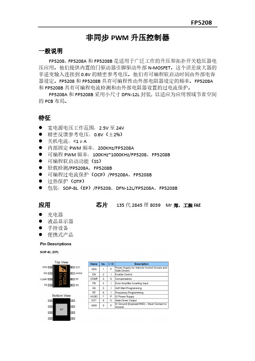
特征⚫宽电源电压工作范围:2.5V至24V⚫精密反馈参考电压:0.6V(±2%)⚫关机电流:<1μA⚫内部固定PWM频率:200KHz/FP5208A⚫可编程PWM频率:100KHz~1000KHz/FP5208、FP5208B⚫可编程软启动功能(SS)⚫轻载检测/FP5208A、FP5208B⚫可编程过电流保护(OCP)/FP5208A、FP5208B⚫过热保护(OTP)⚫包装:SOP-8L(EP)/FP5208、DFN-12L/FP5208A、FP5208B应用芯片135代2845理8039 Mr。
郑,工程FAE⚫充电器⚫液晶显示器⚫手持设备⚫便携式产品功能描述操作FP5208、FP5208A和FP5208B是电压模式升压控制器。
他们用脉冲宽度调制(PWM)。
内部电阻分压器为误差提供0.6V参考电压放大器。
当输出为轻负载时,它们将切换到PSM模式。
它们可以提高效率,但是PSM模式还会增加输出电压纹波。
软启动功能软启动时间可编程,以连接SS引脚与地之间的电容器。
在IC之后启用后,误差放大器的输出被内部软启动功能钳制,从而产生PWM脉冲宽度缓慢增加,从而减少通电时的输入浪涌电流。
软启动偏置电流为1.5µA。
振荡器通过连接电阻,振荡器频率可以从100KHz设置到1000KHzRT与地面之间。
FU-68SDF-V810M168B中文资料

MITSUBISHI (OPTICAL DEVICES) TENTATIVE FU-68SDF-V810MxxxB1.58 µm (L-Band) DFB-LD MODULE WITH SINGLEMODE FIBER PIGTAIL(WAVELENGTH SELECTED, BIAS CIRCUIT INTEGRATED, DIGITAL APPLICATION) DESCRIPTIONModule type FU-68SDF-V810MxxB is a 1.58µm(L-Band) DFB-LD module with single-mode opticalfiber.This module is suitable to a directly modulated light source for use in 2.5Gb/s digital optical communication systems.This module is prepared to expand the wavelength channels into L-Band for Dense-WDM transmission. FEATURESl Multi quantum wells (MQW) DFB Laser Diode modulel Input impedance is 25Ωl Emission wavelength is in 1.58µm bandl High-speed responsel Built-in optical isolatorl Built-in thermal electric coolerl Butterfly packagel With photodiode for optical output monitor APPLICATIONHigh speed transmission systems (~2.5Gb/s)Dense-WDM systemsOPTIONl Wavelength option:1565nm~1625nm are availableABSOLUTE MAXIMUM RATINGS (Tld=Tset)Parameter SymbolConditions Rating UnitOptical outputpowerPf CW15mWForward current If CW150mALaser diodeReverse voltage Vrl-2VReverse voltage Vrd-20VPhotodiodeForward current Ifd-2mACooler current Ipe- 1.3AThermo-electric cooler(Note)Cooler voltage Vpe- 3.1VOperating case temperature Tc--20 ~ 70°CStorage temperature Tstg--40 ~ 85°CNote) Even if the thermo-electric cooler (TEC) is operated within the rated conditions, uncontrolled current loading or operation without heatsink may easily damage the module by exceeding the storage temperature range. Thermistor resistance should be properly monitored by the feedback circuit during TEC operation to avoid the catastrophic damage.1.58 µm (L-Band) DFB-LD MODULE WITH SINGLEMODE FIBER PIGTAIL(WAVELENGTH SELECTED, BIAS CIRCUIT INTEGRATED, DIGITAL APPLICATION) ELECTRICAL/OPTICAL CHARACTERISTICS (Tld=Tset, Tc=25°C unless otherwise noted)Parameter Symbol Test Conditions Limits UnitMin.Typ.Max. Threshold current Ith CW-1025mA Optical output powerat threshold currentPth CW, If=Ith--150µW Operating current Iop CW, Pf=10mW-5095mA Operating voltage Vop CW, Pf=10mW- 1.3 1.8V Input impedance Zin Pf=10mW-25-ΩLight-emission centralwavelengthλc(Note 1)(Note 2)nmCentral wavelength drift withcase temp.∆λc/∆Tc Tc=-20~70°C-1-0pm/°C Laser operating temperature Tset-20-35°C Spectral width∆λ(Note 1), -20dB-0.20.4nm Side mode suppression ratio Sr(Note 1)3340-dB Dispersion penalty Pp(Note 1), at 10-10 BER,+1800ps/nm--2dBCutoff frequency(-1.5dB optical)fc Pf=10mW 3.5--GHzRise and fall time(10~90%)tr, tf(Note 1)--150psecRelative intensity noise Nr CW, Pf=10mW,0.5~3GHz--155-145dB/HzTracking error (Note 3)Er Tc=-20~70°C,APC, ATC--0.5dBDifferential efficiencyηCW, Pf=10mW0.150.250.35mW/mA Linearity∆ηCW, Pf=1~12mW,(Note 4)-20-20% Monitor current Imon CW, Pf=10mW, Vrd=5V0.2-3mATc=25°C35--Optical isolation IsoTc=-20~70°C23--dB Dark current (PD)Id Vrd=5V, Tc=-20~70°C--0.1µA Capacitance (PD)Ct Vrd=5V, f=1MHz--10pF Note 1) 2.48832Gb/s NRZ, 223-1, Pf_ave=5mW, Extinction ratio 10dB, optical return loss of the connectors should be greater than 40dB in order to ensure the specified performance.Note 2) See Table 1.Note 3) Er=max|10×log(Pf / Pf@25°C)|Note 4) Variation of the differential efficiency from the straight line between 1mW and 10mW.1.58 µm (L-Band) DFB-LD MODULE WITH SINGLEMODE FIBER PIGTAIL(WAVELENGTH SELECTED, BIAS CIRCUIT INTEGRATED, DIGITAL APPLICATION) THERMAL CHARACTERISTICS (Tld=Tset, Tc=-20~70°C)Parameter Symbol Test Conditions Limits UnitMin.Typ.Max. Thermistor resistance Rth Tld=25°C9.51010.5kΩB constant of Rth B--3950-K Cooling capacity∆T Pf=10mW, Tc=70°C50--°C-0.61A Cooler current Ipe Pf=10mW, Tc=70°C,Tld=Tset- 1.22V Cooler voltage Vpe Pf=10mW, Tc=70°C,Tld=TsetFIBER PIGTAIL SPECIFICATIONSParameter Limits UnitType SM-Mode field diameter9.5+/-1µmCladding diameter125+/-2µmSecondary coating outer diameter0.9+/-0.1mmConnector FC/PC-Optical return loss of connector40 (min)dBDOCUMENTATION (Tld=Tset)•Fiber output power vs. Laser forward current at Tld=Tset and Tc=-20,25,70°C•BER curves at 2.48832Gb/s modulation•Threshold current (Ith)•Laser forward current (Iop) at Pf=10mW•Laser forward voltage (Vop) at Pf=10mW•Laser operating temperature (Tset) at λc (Note 5)•Monitor current (Imon) at Pf=10mW•Thermistor resistance (Rth)•Cooler current (Ipe) at Pf=10mW and Tc=70°C•Cooler voltage (Vpe) at Pf=10mW and Tc=70°CNote 5) Tset is attached as a reference data. Rth should be used in order to tune the wavelength to the specified value accurately.1.58 µm (L-Band) DFB-LD MODULE WITH SINGLEMODE FIBER PIGTAIL(WAVELENGTH SELECTED, BIAS CIRCUIT INTEGRATED, DIGITAL APPLICATION) Table 1.Type numberλc (nm)Type numberλc (nm)Type numberλc (nm) FU-68SDF-V810M103B1567.13FU-68SDF-V810M139B1582.02FU-68SDF-V810M175B1597.19 FU-68SDF-V810M104B1567.54FU-68SDF-V810M140B1582.44FU-68SDF-V810M176B1597.62 FU-68SDF-V810M105B1567.95FU-68SDF-V810M141B1582.85FU-68SDF-V810M177B1598.04 FU-68SDF-V810M106B1568.36FU-68SDF-V810M142B1583.27FU-68SDF-V810M178B1598.47 FU-68SDF-V810M107B1568.77FU-68SDF-V810M143B1583.69FU-68SDF-V810M179B1598.89 FU-68SDF-V810M108B1569.18FU-68SDF-V810M144B1584.11FU-68SDF-V810M180B1599.32 FU-68SDF-V810M109B1569.59FU-68SDF-V810M145B1584.53FU-68SDF-V810M181B1599.75 FU-68SDF-V810M110B1570.01FU-68SDF-V810M146B1584.95FU-68SDF-V810M182B1600.17 FU-68SDF-V810M111B1570.42FU-68SDF-V810M147B1585.36FU-68SDF-V810M183B1600.60 FU-68SDF-V810M112B1570.83FU-68SDF-V810M148B1585.78FU-68SDF-V810M184B1601.03 FU-68SDF-V810M113B1571.24FU-68SDF-V810M149B1586.20FU-68SDF-V810M185B1601.46 FU-68SDF-V810M114B1571.65FU-68SDF-V810M150B1586.62FU-68SDF-V810M186B1601.88 FU-68SDF-V810M115B1572.06FU-68SDF-V810M151B1587.04FU-68SDF-V810M187B1602.31 FU-68SDF-V810M116B1572.48FU-68SDF-V810M152B1587.46FU-68SDF-V810M188B1602.74 FU-68SDF-V810M117B1572.89FU-68SDF-V810M153B1587.88FU-68SDF-V810M189B1603.17 FU-68SDF-V810M118B1573.30FU-68SDF-V810M154B1588.30FU-68SDF-V810M190B1603.60 FU-68SDF-V810M119B1573.71FU-68SDF-V810M155B1588.73FU-68SDF-V810M191B1604.03 FU-68SDF-V810M120B1574.13FU-68SDF-V810M156B1589.15FU-68SDF-V810M192B1604.46 FU-68SDF-V810M121B1574.54FU-68SDF-V810M157B1589.57FU-68SDF-V810M193B1604.88 FU-68SDF-V810M122B1574.95FU-68SDF-V810M158B1589.99FU-68SDF-V810M194B1605.31 FU-68SDF-V810M123B1575.37FU-68SDF-V810M159B1590.41FU-68SDF-V810M195B1605.74 FU-68SDF-V810M124B1575.78FU-68SDF-V810M160B1590.83FU-68SDF-V810M196B1606.17 FU-68SDF-V810M125B1576.20FU-68SDF-V810M161B1591.26FU-68SDF-V810M197B1606.60 FU-68SDF-V810M126B1576.61FU-68SDF-V810M162B1591.68FU-68SDF-V810M198B1607.04 FU-68SDF-V810M127B1577.03FU-68SDF-V810M163B1592.10FU-68SDF-V810M199B1607.47 FU-68SDF-V810M128B1577.44FU-68SDF-V810M164B1592.52FU-68SDF-V810M200B1607.90 FU-68SDF-V810M129B1577.86FU-68SDF-V810M165B1592.95FU-68SDF-V810M201B1608.33 FU-68SDF-V810M130B1578.27FU-68SDF-V810M166B1593.37FU-68SDF-V810M202B1608.76 FU-68SDF-V810M131B1578.69FU-68SDF-V810M167B1593.79FU-68SDF-V810M203B1609.19 FU-68SDF-V810M132B1579.10FU-68SDF-V810M168B1594.22FU-68SDF-V810M204B1609.62 FU-68SDF-V810M133B1579.52FU-68SDF-V810M169B1594.64FU-68SDF-V810M205B1610.06 FU-68SDF-V810M134B1579.93FU-68SDF-V810M170B1595.06FU-68SDF-V810M206B1610.49 FU-68SDF-V810M135B1580.35FU-68SDF-V810M171B1595.49FU-68SDF-V810M207B1610.92 FU-68SDF-V810M136B1580.77FU-68SDF-V810M172B1595.91FU-68SDF-V810M208B1611.35 FU-68SDF-V810M137B1581.18FU-68SDF-V810M173B1596.34FU-68SDF-V810M209B1611.79 FU-68SDF-V810M138B1581.60FU-68SDF-V810M174B1596.76All wavelengths are referred to vacuum.Tolerance is λc+/-0.05nm.1.58 µm (L-Band) DFB-LD MODULE WITH SINGLEMODE FIBER PIGTAIL(WAVELENGTH SELECTED, BIAS CIRCUIT INTEGRATED, DIGITAL APPLICATION) OUTLINE DIAGRAM(Unit : mm)28.4FU-68SDF-V810MxxxB。
福特技术FU6831 11N 三相BLDC PMSM电机控制器数据手册说明书

FU6831/11NFortior TechFU6831/11NMCU Embedded and Configurable 3-PhaseBLDC/PMSMMotor ControllerDatasheet目录目录 (2)1系统介绍 (3)1.1 特性 (3)1.2 应用场景 (4)1.3 概述 (4)1.4 系统框图 (5)1.4.1 FU6831N功能框图 (5)1.4.2 FU6811N功能框图 (6)2引脚定义 (7)2.1 FU6831N引脚列表 (7)2.2 FU6831N封装-QFN32 (10)2.3 FU6811N引脚列表 (11)2.4 FU6811N封装-QFN32 (14)3封装信息 (15)3.1 QFN32_4X4 (15)4订购信息 (16)1 系统介绍1.1 特性⏹电源电压:VCC: 5~24V⏹双核:8051内核和ME⏹指令周期大多为1T或2T⏹16Kx8bit Flash ROM、带CRC校验功能、支持程序自烧录和代码保护功能⏹256x8bit IRAM,4Kx8bit XRAM⏹ME:集成低通滤波器(LPF)、比例积分器(PI)、SVPWM/SPWM、FOC模块⏹单周期16*16位乘法器,32 / 32位除法器(16个时钟周期)⏹4级优先级中断、16个中断源⏹GPIO个数:FU6831: 18个GPIOFU6811: 19个GPIO⏹定时器:4个通用带抓捕功能可编程定时器1个加强型高级定时器1个带BLDC电机专用定时器⏹I2C/SPI/UART接口⏹模拟外设:12位ADC,支持突发模式采样,可选择内部VREF、外部VREF、VDD5作参考电压ADC通道数:FU6831 QFN32为6通道FU6811 QFN32为7通道内置VREF参考,可配置3V、4V、4.5V、5V输出内置1/2 VDD5或1/2 VREF参考输出内建1个独立运算放大器内建4路模拟比较器,可配置迟滞电压⏹驱动类型:Gate Driver输出(仅适用于FU6811)3P3N Predriver输出(仅适用于FU6831)⏹电机控制方式支持BLDC 方波(120°、150°)、SVPWM/SPWM、FOC⏹支持HALL (HALL IC)、BEMF位置检测⏹FOC驱动支持单电阻电流采样⏹时钟:内置24MHz±2%精准时钟用于系统时钟⏹Watch-dog⏹两线制FICE协议提供在线仿真功能1.2 应用场景无感/有感的BLDC/PMSM、三相/单相感应电机。
68 PIN FEMALE 产品规格书-无铅

.
(a) Function and performance shall be as specified. Not to change for
Physical appearance.
(功能和外觀須正常,不得有任何損壞)
(b)Discontinuity(瞬斷性):≦100 ns
處理等參考所附產品圖面.
5.評定標準5. RATINGS
ITEM項目
RATINGS評定標準
Rated current額定電流
0.5 A per contact(各觸點0.5A)
Dielectric withstanding voltage耐電壓
AC 500V r.m.s ( 1 minute分)
Insulation Resistance絕緣阻抗
(連接器與卡的插入、拔出共10,000次後,測試其接觸阻抗和.插入力、拔出力)
Measured in accordance with PCMCIATest Standard.
Insertion:
39.2N Max
Pulling:
6.67N Min.and 39.2N Max
Contact Resistance:
常溫:15~35℃.Ambient temperature:15~35℃.
常濕:50~85% RH. Ambient humidity:50~85% RH.
4.形狀、尺寸及材質4.Configurations dimensions and materials
構造、尺寸、產品主要的材質、表面See the product drawing attached.
- 1、下载文档前请自行甄别文档内容的完整性,平台不提供额外的编辑、内容补充、找答案等附加服务。
- 2、"仅部分预览"的文档,不可在线预览部分如存在完整性等问题,可反馈申请退款(可完整预览的文档不适用该条件!)。
- 3、如文档侵犯您的权益,请联系客服反馈,我们会尽快为您处理(人工客服工作时间:9:00-18:30)。
MITSUBISHI (OPTICAL DEVICES)FU-68PDF-V520MxxB1.55 m m DFB-LD MODULE WITH POLARIZATION MAINTAINING FIBER PIGTAIL (WAVELENGTH SELECTED, BIAS CIRCUIT INTEGRATED, DIGITAL APPLICATION)DESCRIPTIONModule type FU-68PDF-V520MxxB is a 1.55mm DFB-LD module with polarization maintaining optical fiber.This module is suitable to a CW light source for external modulator for use in 2.5Gb/s and 10Gb/s digital optical communication systems.This module is prepared in accordance with ITU-T recommendation wavelength channel plan for Dense-WDM transmission.FEATURESMulti quantum wells (MQW) DFB Laser Diode modulePolarization maintaining optical fiber pig-tailButterfly packageWith photodiode for optical output monitor APPLICATIONHigh speed transmission systems (~10Gb/s)Dense-WDM systemsABSOLUTE MAXIMUM RATINGS (Tld=Tset)Parameter SymbolConditionsRating UnitOptical output powerPfCW24mW Forward current If CW150mA Laser diode Reverse voltage Vrl 2V Reverse voltage Vrd2mA Cooler currentIpe3.1VOperating case temperature Tc-40 ~ 85°CNote) Even if the thermo-electric cooler (TEC) is operated within the rated conditions, uncontrolled current loadingor operation without heatsink may easily damage the module by exceeding the storage temperature range.Thermistor resistance should be properly monitored by the feedback circuit during TEC operation to avoid the catastrophic damage.MITSUBISHI (OPTICAL DEVICES)FU-68PDF-V520MxxB1.55 m m DFB-LD MODULE WITH POLARIZATION MAINTAINING FIBER PIGTAIL(WAVELENGTH SELECTED, BIAS CIRCUIT INTEGRATED, DIGITAL APPLICATION) ELECTRICAL/OPTICAL CHARACTERISTICS (Tld=Tset, Tc=25°C unless otherwise noted)Parameter Symbol Test Conditions Limits UnitMin.Typ.Max. Threshold current Ith CW-1025mA Operating current Iop CW, Pf=20mW--130mA Operating voltage Vop CW, Pf=20mW--2V Input impedance Zin Pf=20mW-25-W Light-emission centralwavelengthl c CW, Pf=20mW(Note 1)nmCentral wavelength drift withcase temp.Dl c/D Tc Tc=-20~70°C-1-0pm/°C Laser operating temperature Tset-15-35°C Spectral line width D f CW, Pf=20mW--20MHz Side mode suppression ratio Sr CW, Pf=20mW3340-dB Cutoff frequency(-1.5dB optical)fc Pf=20mW2--GHz Polarization extinction ratio Ex CW, Pf=20mW2025-dB Relative intensity noise Nr CW, Pf=20mW,0.5~3GHz--155-145dB/HzTracking error (Note 2)Er Tc=-20~70°C,APC, ATC--0.5dBDifferential efficiency h CW, Pf=20mW0.15--mW/mA Monitor current Imon CW, Pf=20mW, Vrd=5V0.2-4mATc=25°C35--Optical isolation IsoTc=-20~70°C23--dB Dark current (PD)Id Vrd=5V, Tc=-20~70°C--0.1m A Capacitance (PD)Ct Vrd=5V, f=1MHz--10pF Note 1) See Table 1.Note 2) Er=max|10´log(Pf / Pf@25°C)|MITSUBISHI (OPTICAL DEVICES)FU-68PDF-V520MxxB1.55 m m DFB-LD MODULE WITH POLARIZATION MAINTAINING FIBER PIGTAIL(WAVELENGTH SELECTED, BIAS CIRCUIT INTEGRATED, DIGITAL APPLICATION) THERMAL CHARACTERISTICS (Tld=Tset, Tc=-20~70°C)Parameter Symbol Test Conditions Limits UnitMin.Typ.Max. Thermistor resistance Rth Tld=251m mCladding diameter125Threshold current (Ith)Laser operating temperature (Tset) at l c (Note 4)Cooler current (Ipe) at Pf=20mW and Tc=70°C1.55 m m DFB-LD MODULE WITH POLARIZATION MAINTAINING FIBER PIGTAIL(WAVELENGTH SELECTED, BIAS CIRCUIT INTEGRATED, DIGITAL APPLICATION)Table 1.Type number l c (nm)Type number l c (nm)Type number l c (nm) FU-68PDF-520M9B1529.55FU-68PDF-520M39B1541.35FU-68PDF-520M69B1553.33 FU-68PDF-520M10B1529.94FU-68PDF-520M40B1541.75FU-68PDF-520M70B1553.73 FU-68PDF-520M11B1530.33FU-68PDF-520M41B1542.14FU-68PDF-520M71B1554.13 FU-68PDF-520M12B1530.72FU-68PDF-520M42B1542.54FU-68PDF-520M72B1554.54 FU-68PDF-520M13B1531.12FU-68PDF-520M43B1542.94FU-68PDF-520M73B1554.94 FU-68PDF-520M14B1531.51FU-68PDF-520M44B1543.33FU-68PDF-520M74B1555.34 FU-68PDF-520M15B1531.90FU-68PDF-520M45B1543.73FU-68PDF-520M75B1555.75 FU-68PDF-520M16B1532.29FU-68PDF-520M46B1544.13FU-68PDF-520M76B1556.15 FU-68PDF-520M17B1532.68FU-68PDF-520M47B1544.53FU-68PDF-520M77B1556.55 FU-68PDF-520M18B1533.07FU-68PDF-520M48B1544.92FU-68PDF-520M78B1556.96 FU-68PDF-520M19B1533.47FU-68PDF-520M49B1545.32FU-68PDF-520M79B1557.36 FU-68PDF-520M20B1533.86FU-68PDF-520M50B1545.72FU-68PDF-520M80B1557.77 FU-68PDF-520M21B1534.25FU-68PDF-520M51B1546.12FU-68PDF-520M81B1558.17 FU-68PDF-520M22B1534.64FU-68PDF-520M52B1546.52FU-68PDF-520M82B1558.58 FU-68PDF-520M23B1535.04FU-68PDF-520M53B1546.92FU-68PDF-520M83B1558.98 FU-68PDF-520M24B1535.43FU-68PDF-520M54B1547.32FU-68PDF-520M84B1559.39 FU-68PDF-520M25B1535.82FU-68PDF-520M55B1547.72FU-68PDF-520M85B1559.79 FU-68PDF-520M26B1536.22FU-68PDF-520M56B1548.11FU-68PDF-520M86B1560.20 FU-68PDF-520M27B1536.61FU-68PDF-520M57B1548.51FU-68PDF-520M87B1560.61 FU-68PDF-520M28B1537.00FU-68PDF-520M58B1548.91FU-68PDF-520M88B1561.01 FU-68PDF-520M29B1537.40FU-68PDF-520M59B1549.32FU-68PDF-520M89B1561.42 FU-68PDF-520M30B1537.79FU-68PDF-520M60B1549.72FU-68PDF-520M90B1561.83 FU-68PDF-520M31B1538.19FU-68PDF-520M61B1550.12FU-68PDF-520M91B1562.23 FU-68PDF-520M32B1538.58FU-68PDF-520M62B1550.52FU-68PDF-520M92B1562.64 FU-68PDF-520M33B1538.98FU-68PDF-520M63B1550.92FU-68PDF-520M93B1563.05 FU-68PDF-520M34B1539.37FU-68PDF-520M64B1551.32FU-68PDF-520M94B1563.45 FU-68PDF-520M35B1539.77FU-68PDF-520M65B1551.72FU-68PDF-520M95B1563.86 FU-68PDF-520M36B1540.16FU-68PDF-520M66B1552.12FU-68PDF-520M96B1564.27 FU-68PDF-520M37B1540.56FU-68PDF-520M67B1552.52FU-68PDF-520M97B1564.68 FU-68PDF-520M38B1540.95FU-68PDF-520M68B1552.93All wavelengths are referred to vacuum.Tolerance is l c1.55 m m DFB-LD MODULE WITH POLARIZATION MAINTAINING FIBER PIGTAIL(WAVELENGTH SELECTED, BIAS CIRCUIT INTEGRATED, DIGITAL APPLICATION) OUTLINE DIAGRAM(Unit : mm)28.4FU-68PDF-V520MxxB。