cierswb-v1-lab08-sc
安装指南:Compact 5000 I O 8 点安全灌入型数字输入模块说明书

安裝說明Compact 5000 I/O 8 點安全灌入型數位輸入模組目錄編號 5069-IB8S 、5069-IB8SK5069-IB8S 和 5069-IB8SK 模組是 8 點安全灌入型輸入模組。
這些模組在符合 SIL CL3 和 PLe 、Cat. 4 在內等要求的安全控制網絡上提供安全I/O ,依照 IEC 61508、IEC 61511、IEC 62061 和 ISO 13849-1 中所規定。
您可以將 Compact 5000™ I/O 安全模組作為具有 CompactGuardLogix®5380 控制器的本地和遠端 I/O ,以及具有 GuardLogix 5580 控制器的遠端I/O 模組。
5069-IB8SK 模組的功能與 5069-IB8S 模組相同,但也具有保形塗層,可在惡劣環境中加以保護。
使用 Studio 5000 Logix Designer® 軟體設定模組。
Compact GuardLogix 5380 和 GuardLogix 5580 控制器必須使用韌體版本 32.011 或更新版本,才能使用Compact 5000 I/O 安全模組。
Compact 5000 I/O 安全模組使用生產者/消費者通訊模型。
生產者/消費者通訊模型是模組與其他系統裝置之間的一種智慧型資料交換,其中的每一個模組都不用先被輪詢即產生資料。
關於如何使用 Compact 5000 I/O 模組的詳細資訊,請參閱其他資源(第12頁)中所列的出版品。
變更摘要主題頁次關於模組5安裝系統5安裝拆卸式端子座7安裝模組8安裝端蓋9拆卸式端子座配線9從拆卸式端子座中斷電線9使用束線帶10開啟系統電源10移除模組10規格11其他資源12主題頁數移除配線圖有關如何為模組接上電線的資訊,請參閱其他資源(第12頁)中所列的出版物N/ACompact 5000 I/O 8 點安全灌入型數位輸入模組ATTENTION:Read this document and the documents listed in the Additional Resources section about installation, configuration and operation of this equipment before you install, configure, operate ormaintain this product. Users are required to familiarize themselves with installation and wiring instructions in addition to requirements of all applicable codes, laws, and standards.Activities including installation, adjustments, putting into service, use, assembly, disassembly, and maintenance are required to be carried out by suitably trained personnel in accordance with applicable code of practice.If this equipment is used in a manner not specified by the manufacturer, the protection provided by the equipment may be impaired.注意:在安装、配置、操作和维护本产品前,请阅读本文档以及“其他资源”部分列出的有关设备安装、配置和操作的相应文档。
2021年全国大学生电子竞赛仪器和元器件清单

2021年全国大学生电子竞赛仪器和元器件清单2021年全国竞赛仪器和主要元器件清单文章日期:2021-08-0516:45:22文章点击率:462021年全国大学生电子设计竞赛仪器和主要元器件目录【本科组】1.仪器清单60mhz双通道数字示波器100mhz双通道数字示波器500mhz双通道数字示波器低频信号发生器(1hz~1mhz)高频信号发生器(1mhz~120mhz)300mhz信号源双通道函数信号发生器(100mhz,dds)函数发生器(10mhz,dds)低频毫伏表中高频毫伏表中150mhz频率计数字风速仪电子称(最小称量5kg)五位半数字万用表秒表量角器单片机开发系统pld研发系统2.主要元器件目录rl78/g13mcu板(芯片型号r5f100lea),已下发到赛区组委会带防撞圈的多旋翼飞行器,外形尺寸:长度≤50cm,宽度≤50cm;续航时间大于10分钟拎保护板的18650型、容量2000~3000mah的锂离子电池滑线变阻器(10ω/3a)光电传感器100mhz晶体振荡器无线收发模块具备av端子输入的彩色摄像头(彩色制式不减半)大功率电阻(30ω/50w,5ω/25w)大功率控制器管、大功率二极管小型轴流风机(直径5~10cm,5~12vdc)万向节(连接杆直径10mm以下)三维角度传感器或电子陀螺仪变容二极管(2~20pf)【高职高专组】1.仪器清单60mhz双通道数字示波器低频信号发生器函数发生器(10mhz,dds)低频毫伏表三位半数字万用表秒表量角器单片机开发系统pld开发系统2.主要元器件清单单片机最小系统板小型继电器光电传感器角度传感器大功率开关管、大功率二极管电动机(20w以内,STM电机或拎减速器直流电机)小型直流风机。
基于LABVIEW的锂电池监控系统

基于LABVIEW的锂电池监控系统
王成;刘明强;刘迅;邓睿;刘进
【期刊名称】《电源技术》
【年(卷),期】2017(041)001
【摘要】提出了一种基于LabVl EW的锂电池监控系统,整个系统由上位机和下位机组成.下位机通过MSP430F5529单片机及TI的电池管理芯片BQ76PL536对电池组的充放电过程进行控制,同时采集锂电池组每节单体电池电压、主回路电流及电池组温度等信息,MCU通过串口把电池组信息传送到上位机.上位机通过LabVI EW对采集上来的数据进行分析处理,把电池单体电压、主回路电流、电池均衡信息、电池组温度及电池电量等信息实时地显示在前面板上,并保存采集上来的数据.【总页数】4页(P27-29,84)
【作者】王成;刘明强;刘迅;邓睿;刘进
【作者单位】贵州省电子工业研究所,贵州贵阳550004;贵州省电子工业研究所,贵州贵阳550004;贵州省电子工业研究所,贵州贵阳550004;贵州省电子工业研究所,贵州贵阳550004;贵州省电子工业研究所,贵州贵阳550004
【正文语种】中文
【中图分类】TM912
【相关文献】
1.基于LabVIEW的锂电池实时监测系统及SOC估算研究 [J], 李壮;杨兆华
2.基于LabVIEW的锂电池SOC估计与参数监测系统 [J], 魏兴亚;魏宁娴;赵佩
3.基于LabVIEW的锂电池组充电管理系统设计 [J], 汪田洲;吴爱国;马园;王硕
4.基于LabVIEW的锂电池SOC预估与参数监测系统 [J], 李桂娟;张持健;施志刚;李亮;刘雪
5.基于LabVIEW的锂电池组温度状态的在线测试系统研究 [J], 王健;陈磊;温小明因版权原因,仅展示原文概要,查看原文内容请购买。
KSZ8851-16MLL DEMO BOARD 48-PIN ETHERNET CONTROLLE

SD13
SD7 40
CPU_D14 3
6
SD14
SD8 39
CPU_D15 4
5
SD15
SD9 36
SD10 35
33
SD11 34
CPU_CMD
33
SD12 33
R10
SD13 32
CPU_CSN
33
SD14 31
R12
SD15 30
CPU_WRN
33
CMD
11
R14
CPU_RDN
33
CSN
12
R16
5 6 7 8
TANT
C27
R28 10uF
470pF 2.49K
Power 3.3V 0.1uF (red LED)
CSN CMD
4.7K R27 4.7K R29
GBLC03C_0 D3
GND 2 GND
VR 5 3.3VA
INTRN 4.7K R30
VOUT = 1.24 X [ 1 + ( 2.49k/ 1.5K ) ]
5
4
3
KSZ8851-16MLL (48-pin) Demo Board Black Diagram
D
Headers 20x2
RJ45
LAN1 T
KSZ8851-16MLL
Reset
Power
+1.8V
+2.5V
+3.3V
STATUS LEDs
OSC
EEPROM
C
MIC5209YM
25 MHz
AT93C46
x2
2
1
DATE:
系列全自动白度仪

附录 6 常用白度公式
Wr=R457
式中:R457——ISO R457 视亮度(白度) 亨特白度
公司简介
北京辰泰克仪器技术有限公司位于北京市通州区国家环保产业 园区。公司一直致力于颜色测量设备、光学测量设备的开发、研制、 生产、销售,是北京市高新技术企业。拥有设计、生产、检测、销 售、技术支持等规模化的运作能力,公司的产品都以最先进的技术 为根本,以人性化的设计为前提,以创新的思路为标准,以为客户 达到最满意的服务为最终目标。 公司经营仪器仪表设备的技术开发、生产、技术转让、技术咨 询服务。 专业生产 ADCI 系列全自动测色色差计、全自动白度仪。产品 广泛应用于印染、印刷、油漆、涂料、陶瓷、塑料、各粉体行业、 质检部门、非金属矿等各个行业的颜色及色差测量。 公司宗旨------ 公司宗旨------ 北京辰泰克始终发扬“质量第一,服务第一”的精神,坚持以 先进的生产设备、 科学的检测手段、 严格的管理、 雄厚的经济实力、 杰出的科技人才队伍、完善的售后服务、强大的信息网络为基础, 积极开拓,不断探索,努力研制出以适应客户各种不同需求的产品。
北京辰泰克仪器技术有限公司
地 址:北京市通州区梨园中街 259 号(幸福艺居 12 号楼商八) 邮 编:101100 电 话:010-81598278 / 80501168 / 69552528 传 真:010-81598378 / 80501768 网 址: E-mail:ctk@ qjw@
ADCI-60-W 全自动白度仪(白水泥专用型)
完全符合 GB/T 2015-2005 白色硅酸盐水泥新标准的白度测 量标准 测量白水泥的亨特白度值 数据存储量 200 配备粉体恒压压样器
ADCI-2000 全自动白度仪(粉体专用型)
LMS-TestLab安装说明教程文件

注意:这个说明没有多少说明文字,请仔细看清安装过程中的选择LMS TesLLabVVWW」E contactus b rowse cd .exit LMS Test Lab 13A License ServerSoftware License Terms and Conditions Read the release notesRead the installation manualInstall LMS b now...Read the end users guide in stall RLM License server now.-.LMS Viewer and Smart ControlInstall LMS Data Plugin for Active Pictures now. Install LMS Scadas Smart C ontrol now..-■:5 LMS InlernaLiOiial Adobe Aerob臼t Reader Install reader RD叽A Siemens &usin«s选择In stall LMS b now ••安装软件LMS b ISA SetuiWelcome to the Prerequisites WizardThe setup has determined that some of the prerequisites needed torun this program are missing. This wizard will assist you in gettingand installing those prerequisites. Click Next to continue to the list ofprerequisitesClick Finish at any time to completely skip the installation ofprerequisites and jump to the installation of the main program. ClickCancel to cancel the installation and sxit the Setup Wizard.A Siemens Business[<上一^6”帀一步00 >]「题][翊P LMS b 12A SetupPrerequisitesThese programs are needed for the applies b on to run. Click on the check box next to aprerequisite to select it for install or to skip it.□K上一步⑻II下一步闪)R ~矽 LMS Unit System 2.0 Setup< Back 11 Next > ] [~Cancel劃 LMS Unit System 2.0 SetupEnd-User License AgreementPlease read the following license agreement carefullyThe use of this software program requires that you accept on behalf of the company that ordered this ■ software program (the "LICENSEE r ) the terms and conditions of following Software License Terms and Conditio ns. By cicking the *1 agree r ・button below. they will be fuly applicable unless and to the extent otherwise agreed in writing with LMS International NV ・If you doni agree with these terms and conditions, dont push the x l agreed-button. In such case, neither installation nor use of the software program will be allowed and you wil have to contact the response line of one of the LMSofficesSOFTWARE LICENSE TERMSAND CONDITIONS< BackCancel肝 i_nm□ I—MS*A Siewons BusinessWelcome to the LMS Unit System 2.0 Setup WizardThe Setup Wizard will install LMS Unit System 2.0 on your computer. Click "Next' to continue or "Cancel" to exit the Setup Wizard.o I accept the terms in the License AgreementI do not accept the terms in the License Agreement<_Back | Next > Cancel<_Back | Next > CancelInstallation TypeChoose the installation type.Install LMS Unit System 2.0 for:Only for me (Joy) o Everybody (all users)|― Bock || Next a ] | CancelSelect Installation FolderThis is the folder where LMS Unit System 2.0 will be installed.To install in this folder, click ,,Next ,f . To install to a different folder, enter it below or click ,,Browse ,1.Folder:|cAProgram Files (x86)\LMS\觀 LMS Unit System 2.0 SetupBrowse...AOtnlrxmLMS Unit System 2.0 Setup < Back |Install CancelUser Configuration Folder;|C:\LMS\The Group Con figuration Folder is a folder used to provide specific configuration settings to several users. For instance, company templates placed in that folder will be accessible to several Test.Lob users ・ If you don't need such o folder, please leave the field as is. Group Configuration Folder:|C:\LMS\[—< Back 11 Next a ~| CancelLM& Unit System 2.0 SetupClick M Install M to begin the installation. If you v/ant to review or change any of your installation settings, click "Back". Click "Cancel" to exit the wizard ・出J LMS Unit System 2.0 Setup< BackFinish1CancelASiome^s BusinessCompleting the LMS UnitSystem 2.0 Setup WizardClick the "Finish" button to exit the Setup Wizard£3 LMS Tes-tLab 13A SetupIA Siemens BusinessThe Setup Wizard will install LM5 b 13A on your computer. Click ^Next" to continue or "Cancer* to exit the Setup Wizard ・Welcome to the LMS b 13ASetup WizardCancel< Back日 LMS TestLab 13A SetupNew license mechanism introduced based on RLMLMS b Rev. 12A SL1 and higher use a new licensing mechanism that is incompatible with earlier versions ・ You therefore need a new license file. If your installation uses a license server^ you must also instaII a new one. This new license server does not support older versions of LMS TestLab.Please contact your local LMS office and request a new RLM ficense file before installing this version.Please read the installation guide for more details on how to install the new license serverS3 LMS TestLab 13A SetupPlease read the following document carefully. It contains important information about your rights and obligations, as well as limitations and exclusions concerning the use of this software program.A Wnwn> (hAlnoaThe us-e of this software program requires that you accept on behal 1 of the company that ordered this software program (the 'LICENSEE ) the terms and conditions of following Saftv/are License Terms and Conditions. By clicki ng the M l agree*-button below, they will be fully applicable unless and to the extent otherwise agreed in wrting with LMS International NV.If you don't agree with these terms and con<jrtions f dont push the -lagfefr r -button. In such case ・ n either installation nor use of the software program will be allowed and you will have io contact the response Ime of one of the LMS-offices.SOFTWARE LICENSE TERMS AND CONOITIONSThese Software License Terns and Conditions (hereinafter: the Terms and Conditions) s&t forth the terms and conditions according to which LMS Inter national NV (herei natter LMS) agrees to grant to I ICPMQ 匚匚 a e A I IC"O H-e e aro rwrr^/inr*4-e I I-IQ «ort/t I ICPM Q 匚匚 ar-oa e ■♦hoO I agree with the Software Licerse Terms and ConditionsIdo not agree wth the Software LicenseTernrs and ConditionsCancel ]< BackNext >Cancel ]A SWTwrnOl LMS Test Lab 13A Setup貝 i_zimThe system wll set the instanation features based on all .be files in the provried directory. The automatic selection of features based on a license file is optional and can be skipped. If skipped, all products will be selected for installation. In either case you can still change the selected products ually. Automatic license selectionYes t us-e automatic product selection 0 No, do not use automatic product selection Licensn directory path; CABrowse...Please note that if any token features are present in any license file. 9l products wfl be selected.Cancel£3 LMS TestLab 13A SetupProduct SelectionPlease select the products to install▲ { )▼ LMS b Appbcationsi 十产 Desktop Standard & AdvancedAcoustic匸^▼ Environmental ( General Processing and Recording(Rotating Mach in ary 二^▼ Structures Acquisition▼ Structures Analysisi Turbine Testing i_ ▼ Data ServerX p TL-DTP.60.2 LMS [>ata Server th at is part of LMS b Data Management Se 厶b DocumentationHelp(Theory丫 v b Demo DatainCancelLicense Based Automatic Feature Selection (aptron^l) Please enter the path to the license fife.t>t > tSome LMS Te$b workbooks require specific hardware and drivers to be installed・ Please follow installation instructions before connecting thehardware to your computer.LMS HD acoustic camera (HDcam—drivers—installabon.pdf)LMS 3D Solid Sphere array (3Dcam_drivers_installation.fxif)LMS 3D Photo Geometry Scanner (3Dcam_drivers_instalation pdf)These documents are available on the b installation DVD in the Documents folder.Next> Cancel泛 LMS b 13A SetupABwJhnn*Desktcp - Standard (Product cirfe; TL-DTR20.1 rd Desktop - Ad .■ a need (Pro duct cade : TL-DTP.21.1)盘 LMS La b J3A 舁tupSUMS'A 弘”rHbRvilMMl Do you wiah LUS TeatiLafr 1 SAto add exceptions to the Win lows Firewfill?4 H DYes., EPI a bletrs exceptions to tne 'jVindaws. Firewall during the mslalljtion. (Reccnunendedj< Back || Nexti | Cancel 这里选择NO□ LMS Testlab 13A SetupI - j MOMSelect Installation FolderThis is the folder where LMS b 13A will be instaled.To install n this folder, click HexT. To install to a different folder, enter t below or click •Browse**.Install LMS b in the folder:C:\Program Files (x86)\LMSBrowse...£3 LMS Test. Lab 13A SetupSelect User Configuration FolderThis folder will be used for configuration files (project templates, layout, configurate)n,.・・) saved by the user.To use this folder, click m NexT. To use a different folder, enter t below or click "Browse"Important: make sure that you choose a folder on which the user will have read and write permissionsb user configuration folder (*): C:\LM®C)This folder wi be the base folder, used for al user configurations. b will appe nd \UserConfiguration\SLOGN\b 13A\to the folder specified.Browse...Cancel< Back CancelA Stctncrn、Q LMS Test Lab 13A SetupSelect Group Configuration FolderPlease specify whether you want b to use a group folderA Siemens BuUnr%>A group folder is a folder where an administrator can place files which are in common for a group of busers・ These files include project templates, documentation :emplates. print formats, layout files andconfiguration files.9 No, de not use a group configuration folderYes, use a group con figurati on fold erb group configuration tolder (f):C:\LMSX BrowseFile access priority:When accessing files, prioritize the Local folderC)This folder wil be the base foldef. u&ed for all group configuratiom. b wil append\GroupConfiguraton\LMS b 13A\ tothe folder specified.«Bacc I Next > Cancel£3 LMS Test Lab 13A SetupA S'emens RuMnws.Please specify in what way you would like to use the ASAM/ODS data driver on ths machine. You can access ASAM/ODS data using a Corba Names server. In that case, please provide the server name and port numtoer Corba Names Servera Mo. do not use a Corba Names ServerYes. use a Corba Names Server[vBadc ||ASAM/ODS ConfigurationPlease specify the ASAM/ODS configuraOon to useCancel完成后选择安装“ In stall RLM Lice nse server now …”JLMS Tesl.L^b UA ^etupj■A Siemens Busi nessCompleting the LMS b 13A SetupWizardLMS b 13A is installed successftjly. Please dick thf ^Finish" button to exit ttie 虫tup Wizard.Back | FinistiC.anc el岀 LMS RLM 10.0.1 License server SetupSelect License RleSetup v\il use the license file specified below ・ If left empty, you have to copy the license file hter to the daU folder that you specify below.|G: gLM _License_Server V-MS.lic© Configure the license server to look for license files in Cr^rogramData^LMSpcensing and copy the license file to thslocation ・ RecommendedConfigure the license server to look for license files in a specific directory and copy the license file to this location:Browse...<Back Next >CancelLMS RLM 10.0.1 License server SetupDefine the options2l Do not allow to shut down the license server from a remote computerPleaseO specfy the path f&r the server logfile CRLMLOG.txt): |C!^LNJ-icense_ServerV-MSDIog .txt\ Please specify the path for the daemon logfile (LMSLOG.DLOG): |C^LM_License_Server\|ms .dlog.dlog<BackNext >CancelA 5icfncm (knl nenBrowse...劃LMS RLM 10.0.1 Lkens-e server SetupFirewall settings必i_zim Adapt the firewall exclusions...Ifsdected f the installation will modify the firewall settings on your computer, such that the communication between your computer rnd the license server will not x prohibited.[/ Adapt the fireball settings to allow the licensing daemon to pass< Bad [ Next > ] 「Cancel ]上¥ _M& RLM LO.O.l Licence server SetupReady to IiistBllTlhe Setup V/izard is ready to begin the LMS RLM UO.O.lUoenBe server instil日lionL'c /?i5ta ' LKec'il'ie irst-zlatic. It /c_. -ai\ :a e -匚,c卜己】匚亡■亍江LJ「installation settings, dick 'B日ck*. Click r Cancd r bo exit the wizard.< Sack Install匚 ancel 安装结束后将crack\RLM_License_Server目录下的所有文件复制到C:\Program Files (x86)\LMS\LMS RLM 10.0.1 Lice nseserver\Licensing\Bin目录内覆盖掉安装文件,重启电脑即可。
SECO-NCD57000-GEVB NCD57000 mini Evaluation Board
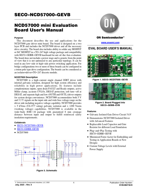
SECO-NCD57000-GEVB NCD57000 mini Evaluation Board User's ManualPurposeThis document describes the use and applications for the NCD57000 gate driver mini board. The board is designed on a two layer PCB and includes the NCD57000 driver and all the necessary drive circuitry. The board also includes ability to solder any MOSFET or SiC MOSFET in a TO−247 high voltage package and compatibility with SECO−GDBB−GEVB baseboard for out−of−the−box evaluation. The board does not include a power stage and is generic from the point of view that it is not optimized to any particular topology. It can be used in any low−side or high−side power switching application. For bridge configurations two or more of these boards can be configured in a totem pole type drive configuration. The boards can be considered as an isolator+driver+TO−247 discrete module.NCD57000 DescriptionNCD57000 is a high−current single channel IGBT driver with internal galvanic isolation, designed for high system efficiency and reliability in high power applications. Its features include complementary inputs, open drain FAULT and Ready outputs, active Miller clamp, accurate UVLOs, DESAT protection, soft turn−off at DESAT, and separate high and low (OUTH and OUTL) driver outputs for system design convenience. NCD57000 accommodates both 5 V and 3.3 V signals on the input side and wide bias voltage range on the driver side including negative voltage capability. NCD57000 provides > 5 kVrms (UL1577 rating) galvanic isolation and > 1200 Viorm (working voltage) capabilities. NCD57000 is available in the wide−body SOIC−16 package with guaranteed 8 mm creepage distance between input and output to fulfill reinforced safety insulation requirements.Collaterals•SECO−NCD57000−GEVB•SECO−GDBB−GEVB•NCD57000Figure 3. SchematicEVAL BOARD USER’S MANUALFigure 1. SECO−NCD57000−GEVBFigure 2. Board Plugged intoSECO−GDBB−EVBFeatures•Galvanic Isolated Gate Driver Circuit 5 kV •Demonstrates NCD57000 Isolated Driver with Advanced Features •Replaceable Load Capacitor and Gate Resistor for different Load Simulation •Plug−and−Play Testing withSECO−GDBB−GEVB •Minimized Form−factor for Embedding and Testing in Application Boards or New Designs•Custom V oltage Levels with External Power SupplyFigure 4. Simplified NCD57000 Block DiagramFigure 5. NCD57000 mini Board − Top ViewFigure 6. NCD57000 mini Board SchematicFigure 7. SECO−GDBB−GEVB Table 1. NCD57000 mini BOARD BOMDescription Designa-tor Quantity Value Comment Footprint ManufacturerCapacitor 0805 1 m F 50 V C1, C3, C53 1 m F CAP0805TDKCapacitor 0805 100 nF 50 V C2, C4, C73100 nF CAP0603Kyocera AVX Capacitor 0805 10 pF 50 V C6110 pF CAP0603KEMETBYG23T−M3/TR D11SMB VishaySemiconductor Schottky Diode D2, D32MBR0540SOD−123ON Semiconductor NCD57000IC11DSO−16_N ON Semiconductor Header, 7−Pin P11Don’t assembly HDR1X7MolexHeader, 3−Pin P21Don’t assembly HDR1X3MolexRES SMD 10 k W 1% 1/10W 0603R1, R2,R3, R4, R5510k RES0603YageoRES SMD 1 k W 1% 1/10W 0603R511k RES0603BournsRES SMD 4.7 W 1% 1/10W 0805RGH1,RGL12 4.7R RES0805YageoPCB Assembly and LayersFigure 8 and Figure 9 shows the top and bottom layouts of the PCB. The PCB is 35 mm x 18 mm x 1 mm (length x width x height) where the width of the PCB is approximately the width of a TO *247 body.Figure 8. NCD57000 mini Board TOP Assembly DrawingFigure 9. NCD57000 mini Board BOTTOM Assembly DrawingI/O ConnectorsThere are 3 I/O connectors including 13 pins described in Table 2 below. The signals on low voltage side are noted as “primary” ground referenced. There is no true “primary”and “secondary” ground but there is 1.2 kV galvanic isolation across the isolation boundary. It is especiallyimportant to maintain isolation in high−side, high−voltage,switching applications where the “secondary” Vcc (P3.2and P3.3) floats Vcc volts above the power supply input voltage:Table 2. I/O CONNECTOR DESCRIPTIONSRef Des Name I/O GND Ref DescriptionValue [V]P1.1Vcc1Power Primary Positive primary power supply 5P1.2Gnd1Power Primary Ground0P1.3IN+Input Primary Non−inverting PWM input 0 − 3.3 (5)P1.4FLT Output Primary Fault flag0 − 5 (3.3)P1.5IN−Input Primary Inverting PWM input 0 − 5 (3.3)P1.6RDY Output Primary Ground 0 − 5 (3.3)P1.7RST Input Primary Reset FLT pin0 − 5 (3.3)P2.1Vcc2Power Secondary Positive branch power supply < 20P2.2Gnd2Power Secondary Ground of the power supply 0P2.3Vee2Power Secondary Negative branch of power supply > −10G (G)Gate Output Secondary Gate pin of a power switch< 20C (D)Collector Output Secondary Collector (drain) pin of a power switch ≤ 1200E (S)EmitterOutputSecondaryEmitter (source) pin of a power switchMounting into Existing PCBThe board can be mounted into an existing power board, shown as “Main PCB” in Figure 6. If there are no components or low profile surface mount components only, the mini SMD EVB can be mounted parallel to the main PCB as shown in Figure 6. The TO−247, power device leads would pass through the mini EVB plated thru−holes and into the main PCB. Or, if necessary, the gate lead of the TO−247, power device can be soldered to the plated thru−hole on the EVB and cut so that it does not contact the main PCB. For mechanical strength, it is preferred that the TO−247 gate lead pass through both PCB’s. This configuration is helpful for already existing application with horizontal TO−247 positions.Recommended procedure for Option 1 Mounting into an existing PCB:1.On the main PCB, isolate the gate drive to theTO−247. If the existing design includes a gatedrive resistor, removing it should serve thepurpose of isolating the gate drive to the TO−247.If there is no series component between the PWMsignal source and the TO−247 gate lead, the gatedrive PCB track will need to be cut.2.Measure the resistance between the PWM sourceand the TO−247 gate lead (or PWM source to gatedrive transformer/isolator if applicable). Verifyreading is high impedance (open).3.If a TO−247 discrete is installed in the main PCB,remove it now.4.Place Kapton or non−conductive tape over themain PCB area directly beneath the EVB.This is to avoid the possibility of having anycomponents on the bottom of the mini SMD EVBtouch components or conductive surfaces on themain PCB.5.Solder a flying lead of bus wire to the main PCB,PWM signal and so on. Make sure there is enoughlength of the PWM input (flying lead) to reachthrough the EVB.6.Solder the TO−247 through just the EVB first7.With the TO−247 installed into the EVB, installand solder the TO−247 leads into the main PCB.8.Solder the other end of the PWM input (flyinglead) to IN+ for non−inverting PWM applicationsor IN− for inverting PWM applications.ing the same size bus wire, solder the remainingconnections between the EVB to the appropriatelocations on the main PCB.10.Solder flying leads for bias voltage. Note that P2are across the isolation boundary from.Mounting into Existing PCB − Option 2If components mounted on the main PCB interfere with mounting the EVB as described by Option 1 (Figure 10), the TO−247 leads can be formed (lead length may need to be added) with the EVB mounted perpendicular to the main PCB as shown in Figure 11. If required, both mounting options allow the application of a heat sink to the TO−247 package. If high dv/dt is present on the drain of the TO−247, the EVB should be angled, away from being parallel to the TO−247, as much as possible.1.On the main PCB, isolate the gate drive to theTO−247 power device. If the existing designincludes a gate drive resistor, removing it shouldserve the purpose of isolating the gate drive to theTO−247. If there is no series component betweenthe PWM signal source and the TO−247 gate lead,the gate drive PCB track will need to be cut.2.Measure the resistance between the PWM sourceand the TO−247 gate lead (or PWM source to gatedrive transformer/isolator if applicable). Verifyreading is high impedance (open).3.If a TO−247 discrete is installed in the main PCB,remove it now.4.Solder a flying lead of bus wire to the main PCB,PWM signal. Make sure there is enough length ofthe PWM input (flying lead) to reach through themini EVB plated thru−hole.5.After the TO−247 leads have been formed, checkfor fit through the EVB and down into the mainPCB6.Solder the TO−247 through just the EVB first7.With the TO−247 installed into the EVB, installand solder the TO−247 leads into the main PCB8.Solder the other end of the PWM input (flyinglead) to IN+ for non−inverting PWM applicationsor IN− for inverting PWM applications.ing the same size bus wire, solder the remainingconnections between EVB to the appropriatelocations on the main PCB.10.Solder flying leads from bias voltage to the EVB.Note that power supply connector is across theisolation boundary.Figure 10. Mounting into Existing PCBLow voltage power supplyFigure 11. EVB Board InstallationsMounting into New PCB DesignThe EVB can also be used as an isolator+driver+TO−247“driver module” that can be integrated into a new PCB design. The gate lead of the TO−247 between the EVB and the main PCB is for mechanical strength only. For main PCB layout, the gate lead extends down through the main PCBand can be soldered to an isolated plated thru−hole. As shown in Figure 12, shoulder pins with appropriate flange are one option that can be used as mounting pins between mini EVB and the main PCB. In the case new design Figure 13 all needed for footprint design.Figure 12. NCD57000 SMD mini Board New Design InstallationsFigure 13. EVB’s PCB Mechanical DataTesting without Installing into a PCBThe EVB can also be tested without installing into a main PCB. However, since this EVB was designed for small form factor there are no test points included for connecting voltage probes. The EVB should be hand probed carefully since the components are very fine pitch or flying leads connected to desired probe points can be attached. The 20Vdc bias (Vcc2 and Gnd2) is on the secondary side of the isolated gate driver IC and therefore has a separate/isolated return ground from the 5Vdc bias (Vcc1 and Gnd2). The recommended series load of below 4.7 nF and 4.7 W is close to what might be representative of a power switch gate drive input impedance. Leaded passive components can be soldered into the TO−247 holes as shown in Figure 14.Alternatively, a TO−247 power switch can also be solderedin place and used as a load for the gate driver board. Note that testing without installing into a power stage, leaves the DESAT pin open since there is no active drain signal. The effect of operating DESAT this way is explained in section ‘DESAT’.Testing with Gate Driver Base BoardAnother very easy way how to test and evaluate more mini boards at same time is to use dedicated base board containing all necessary for easy use. Figure 15 shows typical example where we only need scope for detail waveform analyzing and precise measurement. The base board makes possible connect up to 200 V voltage for power device loading to see impact of non−linear miller capacity to driving performance.Figure 14. Test Configuration of EVB without Installing into Main or Base PCBfor Gate Drive Mini Boards Testing and EvaluatingDESAT SetupDESAT is a type of short circuit or/and over−current protection dedicated to monitoring the I D ·R DS of the MOSFET or Vce_sat voltage for bipolar device like IGBTs.The EVB is preconfigured with R5 = 1 k W (DESAT resistor). The internal DESAT threshold is fixed at V DESAT(TH) = 9 V and the DESAT signal amplitude is adjustable by R5 and HV diode connected in series with R5.R5 = 1 k W may not be the correct resistor value for some applications. If V DESAT > 9 V during normal operation,decrease R5 to lower the signal amplitude. If DESAT is active, the output is driven low. Further, the /FLT output is activated, please refer to datasheet for more details.Basic MeasurementFigure 16 and Figure 17 show basic gate driver board connected to base board according the Figure 15. V ery easily can be evaluated time delays, maximal gate current capability or maximal switch frequency before thermal runaway at given condition and similar. Typically we can measure time between fault event and FLT pin reaction.Typical task is to compare different part number at same time and/or same condition to see online all, for application,important behaviors.Figure 16. Normal Operation for Turn−on and Turn−offIN+I gV GFigure 17. Zoom of Normal Operation for Turn−on and Turn−offIN +I gV GPUBLICATION ORDERING INFORMATIONTECHNICAL SUPPORTNorth American Technical Support:Voice Mail: 1 800−282−9855 Toll Free USA/Canada Phone: 011 421 33 790 2910LITERATURE FULFILLMENT :Email Requests to:*******************onsemi Website: Europe, Middle East and Africa Technical Support:Phone: 00421 33 790 2910For additional information, please contact your local Sales RepresentativeMouser ElectronicsAuthorized DistributorClick to View Pricing, Inventory, Delivery & Lifecycle Information:o nsemi:SECO-NCD57000-GEVB。
一种阵列式小尺寸温度传感装置
项 目来 源 : 国家“ 八六 三” 高技术研究发展计划 ( O 9 A 1 34 ; 2 O A 0 z 1 ) 江苏省 自然科学基金 项 目( K 0 97 ) 江苏省高校科 技成 B 20 2 2 ;
果 产 业 化 推 进 项 目(H1 — ) 江 苏 省 “ 3 ” 程 项 目 J 02; 33 工 收 稿 日期 :0 1 0 — 6 2 1—4 2 修 改 日期 :0 1 0 — 0 2 1 — 8 1
具 有一 定温度 的被 测物 体外形 进行 识别 。
图 2 单 个热 敏 电 阻的 分 压 法 检 测 原 理 图
当采 用交叉式 阵列结 构 , 即阵列 中每一 个测 温 电
阻 一端 与所 在 的列线 相 连 , 另一 端 与所 在 的行 线 相
1 阵 列式 小 尺 寸 温 度传 感装 置 组成
E AC 7 2 G;2 0 E C:3 0 7 3
d i1 . 9 9 j i n 10 — 6 9 2 1 . 1 0 6 o :0 3 6 / .s .0 4 1 9 . 0 1 1 . 2 s
一
种 阵列 式 小 尺 寸 温 度 传 感 装 置 冰
吴 剑 锋 , 王 蕾 , 建 清 于 忠洲 李 ,
所 设 计 的 阵列 式温 度 感 知装 置设 有 主控 制器 、
连 , Ⅳ× 个温度 传感 器 的连接 线数 目为 Ⅳ+ 根 , 则 可大大减少 电阻阵列 测量 所需 连线 数 目。但该 接 线
阵 温度传感器阵列及其测控 电路 , 以温度传感器阵列 方式 同时也 给阵列 中所有 电阻的测量带 来 了问题 , T_ 、 ^ 广 之 l 凡 列 中相邻 电阻对 被测 电阻 的测量 产生影 响 , 使得 该 电 作 为 温度感 知 的核心 , 中 : 其 温度 敏感单 元采 用微 小 尺寸 测温 型高精 度 N C电阻 , T 单个 元件 的平 面尺 寸 不大 于 2m x i 2mm: 有 阵列 交叉 分 布 式 结 构 , n 具 共