ASM9260T文档
WV-ASM100软件包系列使用说明书
与WJ-RT416一起使用WV-ASM100的注意事项1. 关于本说明书本PDF说明书中包括在与WJ-RT416数字硬盘录像机(此后称为RT416)一起使用WV-ASM100软件包系列时值得管理员注意的说明。
本PDF说明书中仅包括管理RT416时与特定型号有关的操作说明。
关于本软件与其他相容设备的基本操作请参阅使用说明书(PDF)和设置说明书(PDF)。
以下数页的描述是基于在电脑上运行Microsoft®Windows®XP Professional的假设进行的。
如果使用不同的操作系统或者不同的设置,操作窗口可能与以下数页显示的有所不同。
使用其他操作系统时,请参阅相应操作系统的使用说明书。
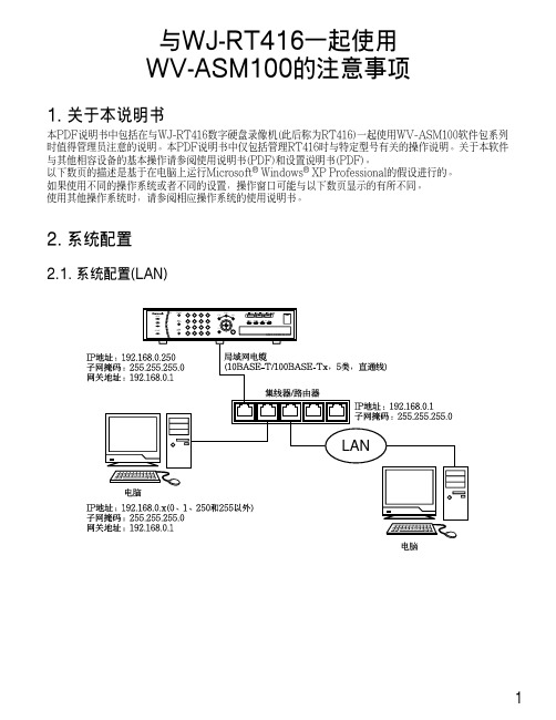
2. 系统配置2.1. 系统配置(LAN)12.2. 系统配置(WAN)3. 关于电脑环境3.1. 使用多监视器系统在有多监视器系统的电脑上使用本软件时,在首选监视器以外的监视器上显示实时图像时可能会显示黑色噪声。
建议使用本软件时不要使用多监视器系统3.2. 使用屏幕保护如果在显示实时图像时启动3维屏幕保护,本软件会因出错意外关闭。
建议使用本软件时不要使用3维屏幕保护。
4. 实时图像显示/回放4.1. 在显示实时图像时每RT416可以显示最多来自16台摄像机的实时图像。
*显示来自5台以上摄像机的实时图像时,来自所有摄像机的实时图像都将按照RT416设置的刷新间隔刷新实时图像。
关于如何配置刷新间隔请参阅RT416上的摄像机的使用说明书。
4.2. 实时图像显示的图像性能不能在16画面上同时显示来自4个以上RT416的实时图像。
如果试图这样做,实时图像的刷新间隔会变慢或者软件操作变得沉重。
建议在9画面上显示来自4个以上RT416的实时图像。
24.3. 回放图像时每RT416可以回放最多来自4台摄像机的记录图像。
每RT416仅允许单一用户回放记录图像。
注:•开始回放时,其他用户所监视的实时图像将会按照RT416设置的刷新间隔刷新。
ASMT-QWB2-NEF0E中文资料

ASMT-QWB2-NxxxxSuper 0.5W White Power PLCC-4Surface Mount LED IndicatorData SheetCAUTION: ASMT-QWB2-Nxxxx LEDs are Class 1C ESD sensitive. Please observe appropriate precautions during handling and processing. Refer to Avago Application Note AN-1142 for additional details.Features• Industry Standard PLCC 4 platform (3.2 x 2.8 x 1.9mm)• High reliability LED package due to enhanced silicone resin material• Mid-Power intensity brightness with optimum flux performance using InGaN chip technologies • Available in Cool White• High optical efficiency 30lm/W• Available in 8mm carrier tape and 7 inch reel • Low Thermal Resistance 60 °C/W • Super wide viewing angle at 120°• JEDEC MSL 2aApplications1. Interior automotivea. Instrument panel backlightingb. Central console backlightingc. Navigation and audio system backlightingd. Dome/Map lightinge. Push button backlightingf. Puddle lampg. Glove compartment illumination 2. Exterior automotivea. Number plate illuminationb. Rear reverse lamp indicator 3. Electronic signs and signals a. Decorative lighting4. Office automation, home appliances, industrial equipmenta. Panel/button backlightingb. Display backlightingDescriptionThe Super 0.5W White Power PLCC-4 SMT LED is first white mid-Power PLCC-4 SMT LEDs using InGaN chip technology. The package can be driven at high current due to its superior package design. The product is able to dissipate the heat more efficiently compared to the Power PLCC-4 SMT LEDs. These LEDs produce higher light output with better flux performance compared to the Power PLCC-4 SMT LED.The Super 0.5W White Power PLCC-4 SMT LEDs are designed for higher reliability, better performance, and operate under a wide range of environmental conditions. The performance characteristics of these new mid-power LEDs make them uniquely suitable for use in harsh condi-tions such as in automotive applications, and in electron-ics signs and signals.To facilitate easy pick and place assembly, the LEDs are packed in EIA-compliant tape and reel. Every reel is shipped in single intensity and color bin, to provide close uniformity. These LEDs are compatible with the IR solder reflow process. Due to the high reliability feature of these products, they also can be mounted using through-the-wave soldering process.Package DrawingNote:1. All Dimensions in millimeters.2. Lead Polarity as shown in Figure 11.3. Terminal Finish: Ag plating4. Encapsulation material: Silicone resin Figure 1. Package DrawingTable 1. Device Selection GuideColor Part Number Luminous Flux, F V[1] (lm)Dice Technology Min. Flux (lm)Typ. Flux (lm)Max. Flux (lm)Test Current (mA)White ASMT-QWB -NEF0E .5 7.0 9.5 50InGaN Notes:1. F V is the total luminous flux output as measured with an integrating sphere at mono pulse conditions.2. Tolerance = ±12%Part Numbering SystemA S M T – Q X1B 2 – N X2 X3 X4 X5Packaging OptionColour Bin SelectionMax. Flux BinMin. Flux BinLED Chip ColorTable 2. Absolute Maximum Ratings (T A = 25 °C)Parameters ASMT-QWB2-Nxxxx DC Forward Current [ ] 50 mA Peak Forward Current [ ] 00 mA Power Dissipation 5 mWReverse Voltage Not Recommended for Reverse Bias Junction Temperature 5 °C Operating Temperature -40 °C to + 0 °C Storage Temperature-40 °C to + 0 °CNotes:1. Derate Linearly as shown in Figure 6.2. Duty Factor = 10%, Frequency = 1kHzTable 3. Optical Characteristics (T A = 25 °C)Color Part NumberDiceTechnologyTypicalChromaticity Coordinates [1]Viewing Angle 2l ½[2] (Degrees)Luminous Efficacy h V [3] (lm/W)Luminous Efficiency h e (lm/W)Luminous Intensity / Total Flux I V (cd) / f V (lm)x y Typ.Typ.Typ.Typ.WhiteASMT-QWB -Nxxxx InGaN0.0.890. 5Notes:1. The dominant wavelength, l D , is derived from the CIE Chromaticity diagram and represents the color of the device.2. q ½ is the off-axis angle where the luminous intensity is ½ the peak intensity.3. Radiant intensity, Ie in watts / steradian, may be calculated from the equation Ie = I V / h V , where IV is the luminous intensity in candelas and h V is the luminous efficacy in lumens / watt.4. φV is the total luminous flux output as measured with an integrating sphere after the device has stabilized.5. Flux tested at mono pulse conditions.Table 4. Electrical Characteristics (T A = 25 °C)Part Number Forward Voltage V F (Volts) @ I F = 150 mAThermal Resistance R q J-P (°C/W)Typ.Max.ASMT-QWB -Nxxxx.64.600.00.10.20.30.40.50.60.70.80.91.0380400420440460480500520540560580600620640660680700720740760780WAVELENGTH - nmR E L A T I V E I N T E N S I T YFigure 2. Relative Intensity Vs. WavelengthFigure 3. Forward Current Vs. Forward Voltage.050100150200250300350012345FORWARD VOLTAGE - VF O R W A R D C U R R E N T - m A0.20.40.60.811.20255075100125150DC FORWARD CURRENT - mAR E L A T I V E L U M I N O U S F L U X (N O R M A L I Z A T I O N A T 150m A )Figure 4. Relative Flux vs. Forward CurrentFigure 5. Relative Intensity Vs. TemperatureFigure 6a. Maximum Forward Current Vs. Ambient Temperature. Derated Based on T JMAX = 125°C, R q J-A = 90°C/W and 110 °C/W.Figure 8. Radiation PatternFigure 7. Forward Voltage Shift Vs. Temperature.-0.15-0.1-0.0500.050.10.150.20.25-50-250255075100JUNCTION TEMPERATURE - °CF O R W A R D V O L T AG E SHI F T -V00.10.20.30.40.50.60.70.80.91-90-60-30306090ANGULAR DISPLACEMENT - DEGREESN O R M A L I Z E D I N T E N S I T YFigure 6b. Maximum forward current vs. solder point temperature. Derated Based on T JMAX = 125°C, R q JP =60°C/W20406080100120140160020406080100120SOLDER POINT TEMPERATURE - °CM A X I M U M F O R W A R D C U R R E N T - mA20406080100120140160020406080100120AMBIENT TEMPERATURE - °CM A X I M U M F O R W A R D C U R R E N T - m A0.20.40.60.811.21.4-50-25255075100125JUNCTION TEMPERATURE - °CN O R M A L I Z E D L U M I N O U S I N T E N S I T YFigure 9. Recommended Pick and Place Nozzle SizeFigure 10. Recommended Pb-free Reflow Soldering Profile.Figure 11. Recommended Soldering Pad Pattern.Note: For detail information on reflow soldering of Avago surface mount LEDs, do refer to Avago Application Note AN 1060 Surface MountingSMT LED Indicator ComponentsNote: Diameter "D" should be smaller than 2.2mmFigure 12. Tape Leader and Trailer Dimensions.Figure 13. Tape Dimensions.Figure 14. Reeling Orientation.This product is qualified as Moisture Sensitive Level 2a per Jedec J-STD-020. Precautions when handling this moisture sensitive product is important to ensure the reliability of the product. Do refer to Avago Application Note AN5305 Handling of Moisture Sensitive Surface Mount Devices for details.A. Storage before use- Unopen moisture barrier bag (MBB) can be storedat <40°C/90%RH for 12 months. If the actual shelflife has exceeded 12 months and the HIC indicatesthat baking is not required, then it is safe to reflowthe LEDs per the original MSL rating.- It is not recommended to open the MBB prior toassembly (e.g. for IQC).B. Control after opening the MBB- The humidity indicator card (HIC) shall be readimmediately upon opening of MBB.- The LEDs must be kept at <30°C / 60%RH at all timeand all high temperature related process includingsoldering, curing or rework need to be completedwithin 672 hours.C. Control for unfinished reel- For any unuse LEDs, they need to be stored insealed MBB with desiccant or desiccator at <5%RH.D. Control of assembled boards- If the PCB soldered with the LEDs is to be subjectedto other high temperature processes, the PCBneed to be stored in sealed MBB with desiccantor desiccator at <5%RH to ensure no LEDs haveexceeded their floor life of 672 hours.E. Baking is required if:- “10%” or “15%” HIC indicator turns pink.- The LEDs are exposed to condition of >30°C / 60%RH at any time.- The LEDs floor life exceeded 672 hours. Recommended baking condition: 60±5°C for 20 hours.Device Color (X1)W WhiteFlux Bin Select (X2X3)Individual reel will contain parts from one bin onlyX Min Flux BinX Max Flux BinFlux Bin LimitsBin ID Min. (lm)Max. (lm)A 4. 0 5.50B 5.507.00C7.009.00D9.00 .50E .50 5.00F 5.00 9.50G 9.50 5.50H 5.50 .00I .004 .00J4 .0056.00K56.007 .00 Tolerance of each bin limit = ± 12%Color Bin Select (X4)Individual reel will contain parts from one full bin only.0Full DistributionA and onlyB and onlyC and 4 onlyD 4 and 5 onlyE 5 and 6 onlyG , and onlyH , and 4 onlyJ , 4 and 5 onlyK4, 5 and 6 onlyM , , and 4 onlyN , , 4 and 5 onlyP , 4, 5 and 6 onlyR , , , 4 and 5 onlyS , , 4, 5 and 6 onlyZ Special Color BinColor Bin LimitsBin ID Limits (Chromaticity Coordinates)x0. 960. 9 0. 00.y0. 590. 680. 970. 84 x0. 9 0. 850. 070. 0 y0. 680. 790. 0. 97 x0. 0. 00. 00. 0 y0. 840. 970. 00. 0 4x0. 00. 070. 00. 0 y0. 970. 0. 470. 0 5x0. 00. 00. 80. 5 y0. 00. 00. 4 0. 44 6x0. 00. 00. 470. 45 y0. 00. 470. 7 0. 5 7x0. 5 0. 80. 640. 60 y0. 440. 4 0. 800. 57 8x0. 450. 470. 670. 64 y0. 5 0. 7 0.40 0. 80Tolerance of each bin limit = ±0.02.VF Bin LimitsBin ID Min.Max.S5 . 0 .50S6 .50 .80S7 .80 4. 0 Tolerance of each bin limit = ±0.1VPackaging Option (X5)Option Test Current Package Type Reel SizeE 50mA Top Mount7 InchHandling PrecautionThe encapsulation material of the product is made of silicone for better reliability of the product. As silicone is a soft material, please do not press on the silicone or poke a sharp object onto the silicone. These might damage the product and cause premature failure. During assembly of handling, the unit should b e held on the body only. Please refer to Avago Application Note AN 5288 for detail information.X - COORDINATEY-COORDINATEFor product information and a complete list of distributors, please go to our web site: Avago, Avago Technologies, and the A logo are trademarks of Avago Technologies, Limited in the United States and other countries.Data subject to change. Copyright © 007 Avago Technologies Limited. All rights reserved.AV0 -0 09EN - July , 007。
41216-01_RevA_SAS_9260-4i_8i_DE-8i

Thank you for purchasing the MegaRAID® SAS (Serial Attached SCSI/Serial AT A II) 9260-4i RAID controller, the SAS 9260-8i RAID controller, or the SAS 9260DE-8i RAID controller (PCI-Express).Please take a few minutes to read this quick installation guide before you install your RAID controller. If you need more information about any topic covered in this guide, refer to the related documents on your MegaRAID Universal Software Suite CD.Note:Record your controller serial number in a safe location in case you need to contact LSI.The MegaRAID SAS 9260-4i is a 6Gb/s, PCI-Express, low-profile RAID controller. It controls four internal SAS/SATA ports through one SFF-8087 Mini SAS 4i internal connector. The MegaRAID SAS 9260-8i is a 6Gb/s, PCI-Express, low-profile RAID controller. It controls eight internal SAS/SAT A ports through two SFF-8087 Mini SAS 4i internal connectors. There are two differences between the SAS 9260-4i RAID controller and the SAS 9260-8i RAID controller:–The SAS 9260-4i supports four ports and the SAS 9260-8i supports eight ports–The 9260-4i does not contain the JT7 connector, which is for ports 7–4Note:The SAS 9260DE-8i RAID controller is the same as the SAS 9260-8i RAID controller except thatthe 9260DE-8i RAID controller offers datasecurity through disk encryption.Note:SAT A II is the only type of SAT A supported by these RAID controllers.Y ou can connect the LSI intelligent Battery Backup Unit 07 (LSIiBBU07) directly to these RAID controllers. For more information about this battery, refer to the Intelligent Battery Backup Units for 1078-based MegaRAID Products User’s Guide on the MegaRAID Universal Software Suite CD.R A I D C O N T R O L L E R I N S T A L L A T I O NStep1Unpack the RAID ControllerUnpack the RAID controller in a static-freeenvironment. Remove it from the antistatic bag,and inspect it for damage. If the RAID controllerappears to be damaged, or if the MegaRAIDUniversal Software Suite CD is missing, contactLSI or your MegaRAID OEM supportrepresentative.The CD contains utility programs, device driversfor various operating systems, and the followingdocumentation:•MegaRAID SAS 6Gb/s RAID ControllersUser’s Guide•MegaRAID SAS Software User’s Guide•MegaRAID SAS Device Driver InstallationUser’s Guide•Software license agreementStep2Prepare the ComputerT urn off the computer, and unplug the powercords from the rear of the power supply. Removethe cover from the computer.Step3Review the Jumpers and the ConnectorsFigure1 shows the location of the jumpers andthe connectors on the RAID controller. Thejumpers are set at the factory, and you usually donot need to change them.Back up your data before you change yoursystem configuration. Otherwise, you might losedata.Before you install the RAID controller, make surethat the computer is disconnected from the powerand from any networks.!CAUTION!CAUTIONMegaRAID SAS 9260-4i, SAS 9260-8i, and SAS 9260DE-8i RAID ControllersQuick Installation GuideFigure 1Layout of the MegaRAID SAS 9260-8i/9260DE-8i RAID ControllerT able 1 describes the jumpers and the connectors on the SAS 9260 RAID controllers.Table 1Jumpers and ConnectorsNote:JT1, JT2, and JT4 are behind the LSIiBBU07 when it is installed, but they are still accessible.Step 4Install the RAID ControllerInsert the RAID controller in a PCI Express slot on the motherboard, as shown in Figure 2. Press down gently, but firmly, to seat the card correctly in the slot. Secure the RAID controller to the computer chassis with the bracket screw.Note:This is a PCI Express x8 card and it can operate in x8 or x16 slots. However, some PCI-E slots support only PCI-E graphics cards; if a RAID controller is installed, it will not function. Note:Refer to the guide for your motherboard for information about the PCI Express slot.Jumper/Connector Type DescriptionJT1Write-pending Indi-cator (dirty cache) LED connector 2-pin connector Connects to an LED that indicateswhen the data in the cache has yet to be written to the storagedevices. Used when the write-back feature is enabled.JT2SAS Activity LED header2-pin connectorConnects to an LED that indicates drive activity.JT3Battery Backup connector20-pin connectorConnects the LSIiBBU07 intelli-gent Battery Backup Unit directly to the RAID controller.JT4Global Drive Fault LED header2-pin connector Connects to an LED that indicates whether a drive is in a fault condition.JT6x4 SAS Ports 3–0Mini SAS 4i connector Connects the cables from the con-troller to SAS drives or SATA II drives, or a SAS expander.JT7x4 SAS Ports 7–4Mini SAS 4i connectorConnects the cables from the con-troller to SAS drives or SATA II drives, or a SAS expander.1.The SAS 9260-4i RAID con-troller does not have this con-nector.JT8Modular RAID Key header2-pin connector Reserved for LSI use.JT9Set FactoryDefaults connector2-pin connectorReturns the board settings to the defaults set in the factory.JT10LSI Test header2-pin connector Reserved for LSI use.JT11IPMI-style SMBus (System Manage-ment)/I 2C header3-pin shielded headerProvides enclosure management support.JT12Individual Drive Fault LED headerfor Eight Phys (0-7)16-pin connector Indicates drive faults. There is oneLED per port. When lit, each LED indicates the corresponding drive has failed or is in the Unconfig-ured-Bad state. Refer to theMegaRAID SAS Software User’s Guide for more information.The LEDs function in a direct-attach configuration (there are no SAS expanders). Direct attach is defined as a maximum of one drive connected directly to each port.This header is used for RAID controllers with internal SAS ports.JT13Universal Asyn-chronous Receiver/Transmitter (UART) debugging4-pin connectorReserved for LSI use.Jumper/Connector Type DescriptionFigure2Installing the MegaRAID SAS 9260-8i/ 9260DE-8i RAID ControllerStep5Configure and Install the SAS Devices, SATA II Devices, or Both in the Host Computer CaseRefer to the documentation for the devices for anypreinstallation configuration requirements.Step6Connect the RAID Controller to the SASDevices, SATA II Devices, or Both in the HostComputer CaseUse SAS cables to connect the RAID controller toSAS devices, SATA II devices, or both. SeeFigure1 to view the connector locations.Refer to the MegaRAID 6Gb/s SAS RAIDControllers User’s Guide on the MegaRAIDUniversal Software Suite CD for detailedinformation about the SAS cables.Step7Turn on the Power to the ComputerReinstall the computer cover, and reconnect thepower cords. Turn on the power to the computer.Make sure that the power is turned on to the SASdevices and the SATA II devices before or at thesame time that the power to the host computer isturned on. If the power is turned on to thecomputer before it is turned on to the devices, thecomputer might not recognize the devices.The firmware takes several seconds to initialize.During this time, the controller scans the ports. Step8Run the WebBIOS Configuration UtilityRun the WebBIOS Configuration Utility toconfigure the groups and the virtual drives. Whenthe message Press<Ctrl><H> for WebBIOSappears on the screen, immediately pressCTRL+H to run the utility.Note:Refer to the MegaRAID SAS Software User’s Guide on the MegaRAID Universal SoftwareSuite CD for detailed steps on configuring groupsand virtual drives.Step9Install the Operating System DriverThe RAID controller can operate under variousoperating systems, but you must install thesoftware drivers first.The MegaRAID Universal Software Suite CDincludes the software drivers for the supportedoperating systems, along with documentation.Y ou can view the supported operating systemsand download the latest drivers for RAIDcontrollers from the LSI website at:/cm/DownloadSearch.do.Access the download center, and follow the stepsto download the driver.Refer to the MegaRAID SAS Device DriverInstallation User’s Guide on the MegaRAIDUniversal Software Suite CD for more informationabout installing the driver. Be sure to use thelatest service packs that are provided by theoperating system manufacturer and to review thereadme file that accompanies the driver.S U P P O R T E D R A I D L E V E L SThe RAID controllers support drive groups using the following RAID levels:•RAID 0 (data striping): Data is striped across all drives in the group, enabling very fast data throughput. There is no data redundancy. All data is lost if any drive fails.•RAID 1 (drive mirroring): Data is written simultaneously to both drives in the drive group, providing complete data redundancy if one drive fails. RAID 1 supports an even number of drives from 2 to 32 in a single span.•RAID 5 (drive striping with distributed parity): Data is striped across all drives in the group. Part of the capacity of each drive stores parity information that reconstructs data if a drive fails. RAID 5 provides good data throughput for applications with high read request rates.•RAID 6(drive striping with distributed parity across two drives): Data is striped across all drives in the group and two parity drives are used to provide protectionagainst the failure of up to two drives. In each row of data blocks, two sets of parity data are stored.•RAID 00: RAID 00 is a spanned drive group that createsa striped set from a series of RAID 0 drive groups.41216-01 Rev. A, July 2009Find a list of LSI Corporation’s U.S. distributors, international distributors, sales LSI, the LSI logo design, and MyStorage are trademarks or registered trademarks of LSI Corporation. All other brand and product names may be trademarks of their respective companies.Copyright © 2009 by LSI Corporation. All rights reserved.LSI Corporation reserves the right to make changes to any products and services herein at any time without notice. LSI does not assume any responsibility or liability arising out of the application or use of any product or service described herein, except as expressly agreed to in writing by LSI; nor does the purchase, lease, or•RAID 10 (RAID 1 and RAID 0 in spanned groups): RAID 10 uses mirrored pairs of drives to provide complete data redundancy. RAID 10 provides high data throughput rates.•RAID 50 (RAID 5 and RAID 0 in spanned groups): RAID 50 uses both parity and drive striping acrossmultiple drives to provide complete data redundancy.RAID 50 provides high data throughput rates.•RAID 60 (RAID 6 and RAID 0 in spanned groups): RAID 60 uses both distributed parity across two parity drives and drive striping across multiple drives to provide complete data redundancy and high fault tolerance. Note:Refer to the MegaRAID SAS Software User’s Guide on the MegaRAID Universal SoftwareSuite CD for more information about RAID levels.T E C H N I C A L S U P P O R TFor assistance in installing, configuring, or running your SAS 9260-4i, 9260-8i, or 9260DE-8i RAID controller, contact your LSI Technical Support representative. Click the following link to access the LSI T echnical Support page for storage and board support:/support/storage/tech_support/index.html From this page, you can send an email, call Technical Support, or submit a new service request and view its status. E-mail:/support/support_form.htmlPhone Support:/support/storage/phone_tech_support/ index.html1-800-633-4545 (North America)00-800-5745-6442 (International)Note:The international toll-free number does notrequire country specific access codes.。
9260-8i卡操作手册

4024RAID卡使用手册本册主要介绍RAID卡常用功能,raid的创建,参数配置及管理软件的介绍下面先从开机启动时如何进入管理界面开始介绍1.当机器开启后,显示器出现阵列卡检测信息时,会提示用户是否要进入管理界面对阵列卡进行操作,此时按下Ctrl+H即可,如下图1图12.按下Ctrl+H后,进入控制器选择界面,若只有一张卡,便如下图2所示,多张卡会分行显示,选择相应的控制器后,按start进入管理界面图23.若出现图3所示:Foreign Config(s) Found.则说明当前使用的硬盘存在之前使用的raid设定信息。
若要重新导入raid设定,可点击Preciew尝试;对于正常新建raid,请直接点击clear 进入下一步图34.此时,会出现提示窗,如图4,告知当前的操作会清除掉硬盘上之前的所有raid配置信息,是否要继续,请直接点击yes进入下一步:图45.图5所示为RAID卡的WebBIOS管理界面,左侧边栏为功能设定选项,右侧部分会显示阵列和磁盘的相关状态信息。
图56.新建raid时,请点击左侧Configuration Wizard选项,进行相关操作。
如图6Raid配置向导,点击可创建Raid图67.点击Configuration Wizard后,会出现下图7所示界面,提示选择相关操作,A:Clear Configuration 选择此项后,可清除已经存在的raid 设定B:New Configuration 选择此项后, 清除已经存在的raid设定,并可继续进行新的Raid配置。
C: Add Configuration 选择此项后,可新建Raid,对已经存在的Raid不会有任何影响。
通常情况下,Clear Configuration用于清除阵列卡上所有的已经存在的阵列信息,一旦进行,所有的Raid信息都不存在。
而Clear Configuration选项一般为客户首次进行Raid设定,此时阵列卡上一般不存在阵列。
Lsi 9260-8i阵列卡操作手册(简版)

Lsi9260-8i阵列卡操作手册目录:一、如何进入RAID卡BIOS界面二、BIOS主界面三、创建阵列四、如何创建与删除热备盘五、删除阵列一、如何进入RAID卡BIOS 界面阵列卡信息按下组合键进入BIOS界面1、开机到此界面时按下组合键Ctrl+H进入RAID卡BIOS 管理界面。
二、WebBIOS主界面0、Advanced Software Options高级软件选项1、Controller Selection选择RAID卡(机器上安装有多张RAID卡时)2、Controller Properties RAID卡属性设置3、Scan Devices刷新硬盘设备4、Virtual Drives虚拟磁盘管理5、Drives物理硬盘管理6、Configuration Wizard创建阵列配置7、Logical View/Physical View查看逻辑/物理磁盘(点击切换)8、Events事件9、Exit退出三、创建阵列1、查看物理硬盘在界面右面可看到可用于组建RAID 的硬盘○1Slot :0——硬盘的物理位置,在0号端口。
○2Unconfigured Good ——好的,未配置的硬盘。
2、点击“Configuration Wizard ”进入创建阵列配置,如图:○1Clear Configuration 清除所有的阵列配置信息○2New Configuration 新建RAID 配置(会清除所有的数据,一般只在新机器第一次做阵列时选择)○3Add Configuration 增加RAID 配置3、一般选择Add Configuration ,按Nex t 进入下一步进入Select Configuration Method 界面:12○1Manual Configuration 手动配置○2Automatic Configuration 自动配置以下先以WD 2TB*4组建RAID10为例:3、选Manual Configuration 手动配置进入下一步:○1在左边“Drives ”框中选择要做RAID 的磁盘,按住Ctrl 键可一次同时选择多个。
ASM 更换存储实施手册

东软秘密文档编号:第版分册名称:第册/共册ASM更换存储实施手册河北东软软件有限公司变更履历目录第一章迁移votedisk 和OCR 文件 (1)1.1创建新的OCR磁盘组,存放OCR 文件 (1)1.2查看当前votedisk (1)1.3替换votedisk (1)1.4查看当前的OCR 文件 (1)1.5添加新的OCR 磁盘组 (2)1.6删除以前的OCR 磁盘组 (2)1.7查看OCR 以及votedisk (2)第二章迁移数据文件 (4)2.1查看原有的磁盘和磁盘组 (4)2.2把新建的asm 磁盘添加到DATA 磁盘组 (4)2.3手动重新平衡磁盘 (6)2.4删除旧磁盘 (6)第三章迁移过程评估及建议 (7)第一章迁移votedisk 和OCR 文件1.1创建新的OCR磁盘组,存放OCR 文件1.2查看当前votedisk[grid@S-SI-RAC-2 ~]$ crsctl query css votedisk;## STATE File Universal Id File Name Disk group--- -------- --------------------- ------------ --------------1. ONLINE 6cac17d212874f2dbfc1920251c56f0b (/dev/asm-diskb) [OCR] Located 1 voting disk(s).1.3替换votedisk[grid@S-SI-RAC-2 ~]$ crsctl replace votedisk +NEWOCRSuccessful addition of voting disk 1c92c7d8a1324f61bfdfb436043dd2ba. Successful addition of voting disk 5ea9a153d7804f1fbfac1f541ebf0a31. Successful addition of voting disk 110df84917994f57bfda4f22daac4006. Successful deletion of voting disk 6cac17d212874f2dbfc1920251c56f0b. Successfully replaced voting disk group with +NEWOCR.CRS-4266: Voting file(s) successfully replaced1.4查看当前的OCR 文件[root@S-SI-RAC-1 ~]# ocrcheckStatus of Oracle Cluster Registry is as follows :Version : 3Total space (kbytes) : 262120Used space (kbytes) : 2912Available space (kbytes) : 259208ID : 1457159054Device/File Name : +OCRDevice/File integrity check succeededDevice/File not configuredDevice/File not configuredDevice/File not configuredDevice/File not configuredCluster registry integrity check succeededLogical corruption check succeeded1.5添加新的OCR 磁盘组[root@S-SI-RAC-1 ~]# ocrconfig -add +NEWOCR1.6删除以前的OCR 磁盘组[root@S-SI-RAC-1 ~]# ocrconfig -delete +OCR1.7查看OCR 以及votedisk[root@S-SI-RAC-1 ~]# ocrcheckStatus of Oracle Cluster Registry is as follows :Version : 3Total space (kbytes) : 262120Used space (kbytes) : 2912Available space (kbytes) : 259208ID : 1457159054Device/File Name : +NEWOCRDevice/File integrity check succeededDevice/File not configuredDevice/File not configuredDevice/File not configuredDevice/File not configuredCluster registry integrity check succeededLogical corruption check succeeded[root@S-SI-RAC-1 ~]# crsctl query css votedisk;## STATE File Universal Id File Name Disk group-- ----- ----------------- --------- ---------1. ONLINE 1c92c7d8a1324f61bfdfb436043dd2ba (/dev/asm-diski) [NEWOCR]2. ONLINE 5ea9a153d7804f1fbfac1f541ebf0a31 (/dev/asm-diskj) [NEWOCR]3. ONLINE 110df84917994f57bfda4f22daac4006 (/dev/asm-diskk) [NEWOCR] Located 3 voting disk(s).第二章迁移数据文件2.1查看原有的磁盘和磁盘组SQL> select group_number,name,path ,mount_status from v$asm_disk;GROUP_NUMBER NAME PATH MOUNT_S ------------------------ ---------------------- ------------------------------ -------------0 /dev/asm-diskm CLOSED0 /dev/asm-diskl CLOSED2 FRA_0000 /dev/asm-diskh CACHED3 OCR_0002 /dev/asm-diskd CACHED1 DATA_0001 /dev/asm-diskf CACHED3 OCR_0001 /dev/asm-diskc CACHED1 DATA_0002 /dev/asm-diskg CACHED1 DATA_0000 /dev/asm-diske CACHED3 OCR_0000 /dev/asm-diskb CACHED4 NEWOCR_0001 /dev/asm-diskj CACHED4 NEWOCR_0002 /dev/asm-diskk CACHED4 NEWOCR_0000 /dev/asm-diski CACHED SQL> select group_number ,name from v$asm_diskgroup;GROUP_NUMBER NAME------------ ------------------------------1 DATA2 FRA3 OCR4 NEWOCR2.2把新建的asm 磁盘添加到DATA 磁盘组保证新建的磁盘文件容量大于原来该磁盘组空间使用总和。
V9260数据手册
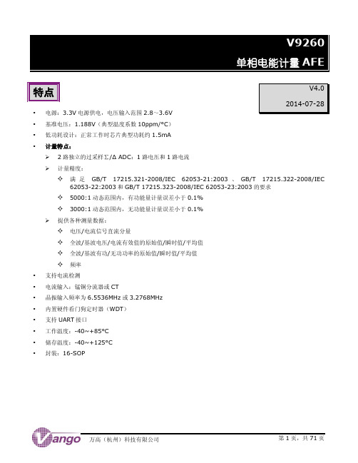
V9260
目录
目录
特点 .................................................................................................................................. 1 声明 .................................................................................................................................. 2 目录 .................................................................................................................................. 3 引脚分布图 .......................................................................................................................... 5 性能参数 ............................................................................................................................. 7 绝对最大额定值 .........................................................................................................
LaCie Biggest FW800 2TB 外部硬盘说明书

Hasta 2 TB de almacenamientoLa unidad Biggest FW800 de LaCie dispone de cuatro discos intercambiables “en caliente”. Cada disco ofrece una gran capacidad de 250 ó 500 GB. Por eso es capaz de almacenar hasta 2 TB de datos. Esta potente torre RAID cuenta con doble interfaz USB 2.0 y FireWire 800 para poder usarla tanto en PC como en Mac.Seguridad RAIDGracias a su tecnología RAID, LaCie Biggest FW800 admite varios niveles de configuración: RAID 0, 0+1 y 5, así como RAID 5 + unidad de repuesto. Permite combinar sus discos en función de las distintas necesidades de capacidad,seguridad o velocidad. El sistema RAID resulta también perfecto para recuperar los datos ante un posible fallo del disco.Rápida y fácil de usarEsta nueva solución RAID de LaCie está diseñada pensando en las necesidades de los profesionales del audio y vídeo. Potente y rápida, alcanza una gran velocidad de transferencia de hasta 70 MB/s. Además, Biggest FW800 es comparativamente más asequible que los sistemasRAID tradicionales. Es perfecta para almacenar y proteger una gran cantidad de archivos y bases de datos de forma segura. Los cuatro discos que componen Biggest de LaCie se instalan fácilmente sin necesidad de driver.Recuperación de datos “en caliente”LaCie Biggest FW800 garantiza la máxima seguridad de datos en cualquier situación. Permite proteger los archivos importantes incluso ante un posible fallo de un disco, ventilador o cable de alimentación. Los ficheros del disco afectado se envían a otro reservado como “unidad de repuesto”. De esta forma, la información estará protegida en todo momento. Además, Biggest FW800 cuenta con un sistema de seguridad inteligente que apaga la unidad si su temperatura supera los 55°C, protegiendo la torre y los datos.• Enorme capacidad de almacenamiento de hasta 2 TB • Cuenta con la tecnología RAID más segura • Es muy fácil de usar y de instalarLaCie Biggest FW8001TB · 2TBSeguridad, velocidady potencia RAID• Biggest FW800 con 4 discos duros SATA en bandejas* 1 TB (terabyte) equivale a 1.000 GB. 1 GB equivale a 1.000.000.000 bytes. La capacidad total accesible varía en función del entorno operativo (normalmente entre un 5 -10% menos). La capacidad de almacenamiento disponible depende del nivel RAID: RAID 0 = 100%, RAID 0+1 = 50%, RAID 5 = 75% y RAID 5+repuesto = 50%.061107。
- 1、下载文档前请自行甄别文档内容的完整性,平台不提供额外的编辑、内容补充、找答案等附加服务。
- 2、"仅部分预览"的文档,不可在线预览部分如存在完整性等问题,可反馈申请退款(可完整预览的文档不适用该条件!)。
- 3、如文档侵犯您的权益,请联系客服反馈,我们会尽快为您处理(人工客服工作时间:9:00-18:30)。
ASM9260T 主控芯片采用ARM926EJS 内核,主频可以达到240MHZ 。
同时集成了16KBytes 指令Cache 和16KBytes 数据Cache ,以及32位SDRAM/NOR Flash 控制器。
ASM9260T 还集成了丰富的外设控制器,比如USB ,Ethernet ,NAND ,LCD 控制器,多达10个UART 等等,使得ASM9260T 非常适用于工业控制场合。
另外,9260T 还可采用3D 封装形式将一颗16位数据宽度的256Mbit 的SDRAM 封装在芯片内部,从而节省出大量芯片管脚给其他模块使用。
Features
● 240MHz ARM926EJ-S ARM Thumb Processor
16KBytes Data cache ,16KBytes Instruction cache, MMU
● Memories
32bit external bus interface supporting 4-bank SDRAM, Nor-flash, SRAM
NAND Flash controller with 16bit BCH ECC per 512 bytes ,supporting newest MLC
NAND Flash
Support Quad-SPI flash, which can reach four times bandwidth than traditional SPI
flash
Two 4Kbytes internal SRAM, single cycle access at system speed
One 32Kbytes internal ROM, embedding bootstrap routine
●
Peripherals
紫芯技术交流群:332441072
ITU 656/601 Image sensor interface
24bit LCD controller, support TFT/STN panel, also support LCD interface format
Two USB2.0 HS OTG controller with on-chip high-speed transceiver
One 10/100Mbps Ethernet MAC controller, both support MII or RMII interface
One high speed GPIO DMA, can output parallel data to 32/16/8 bits IO at half of system frequency
One high speed SD/MMC card controller, also can be used as SPI controller
Two SPI controller, support master or slave operation, support full-duplex operation Four 32bit Timers, each timer has four output channels and one input channel
Two I2C interface
Six USARTs
Three UARTs
One 8-wire UART, support modem control signal
Two CAN interface
One 8-channel 12bit ADC
One 12bit DAC
Two 5.1ch I2S interface
One Motor PWM interface
One QEI interface
●System
120MHz 32bit multi-layer AHB Bus Matrix
Two DMA controller with 16 independent DMA channels
Boot from ROM, Nand Flash, Nor Flash, SPI Flash
Reset Controller with on-chip power-on reset
One PLL for system and two PLL for USB system
Advanced Interrupt controller
Watch dog timer and RTC Timer
●IO
3D Package with one 256Mbit sdram die in package
LQFP 216/176/128 package, totally 160 digital pin which can be used as GPIO or peripheral’s IO
Each pin can be programmed to input or output, can be set to pull up or pull down。