2843B
3843B资料
TL3843BD-8
SOIC – D (8 pin)
Reel of 2500 Tube of 75
TL3843BDTL3844BDR-8
Tube of 75
TL3845BD-8
Reel of 2500
TL3845BDR-8
Tube of 75
TL3842BD
Copyright © 2006, Texas Instruments Incorporated
元器件交易网
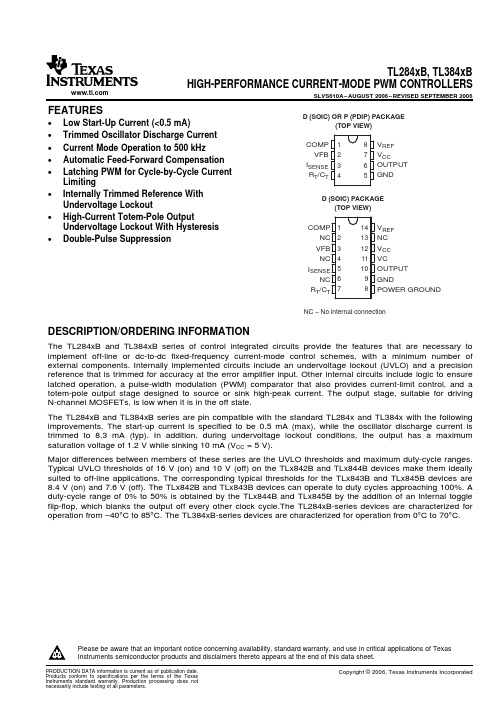
TL284xB, TL384xB HIGH-PERFORMANCE CURRENT-MODE PWM CONTROLLERS
SLVS610A – AUGUST 2006 – REVISED SEPTEMBER 2006
S
R
CurrentSense
Comparator
PWM Latch
Submit Documentation Feedback
3
元器件交易网
TL284xB, TL384xB HIGH-PERFORMANCE CURRENT-MODE PWM CONTROLLERS
Reel of 2500
TL3842BDR
Tube of 75
TL3843BD
SOIC – D (14 pin)
Reel of 2500 Tube of 75
TL3843BDR TL3844BD
Reel of 2500
TL3844BDR
Tube of 75
TL3845BD
Reel of 2500
TL3845BDR
RT/CT 7
14 VREF 13 NC 12 VCC 11 VC 10 OUTPUT 9 GND 8 POWER GROUND
uc2843

UC3842B,UC3843B,UC2842B,UC2843B,NCV3843BV高性能电流模式控制器UC3842B,UC3843B系列是高性能定频电流模式控制器。
它们是专门为脱机与DC-DC转换器的应用所设计的,设计者以最少的外部元器件组合提供了一种最物超所值的解决方案。
这些集成电路以一个trimmed振荡器控制精确占空比,一个温度补偿基准,高增益误差放大器,电流采样比较器,与一个非常适宜驱动功率MOSFET的高电流图腾柱输出为特征。
此外还包括保护特性,这种特性由带有滞后的输入与基准欠压锁定,周期限流,可设定的输出死区时间与单脉冲测量锁存组成。
这些设备有两种封装形式,一种是表面塑封的8针双列直插封装形式(SOIC-8),一种是表面塑封的14针封装形式(SOIC-14)。
SOIC-14封装的设备有独立的电源管脚与接地管脚用于这个图腾柱输出级。
UC842B导通时的门限值为16V,关断时为10V,非常适宜于脱机状态下的转换器。
UC843B 则为8.5V(导通时)与7.6V(关断时),适宜较低电压状态下转换器的应用。
特性·精确控制频率的trimmed振荡器·保证在250kHz下的振荡频率·可达500kHz的电流模式运行·自动的前馈补偿·用于周期限流的闭锁PWM·带有欠压锁定的内部trimmed基准·高电流图腾柱输出·带有滞后的欠压锁定·低启动与运行电流·实现无铅封装括号中标注的是后缀为D的SOIC14封装管脚号图1.结构简图管脚连接订购信息详细的订购及采购信息参加本数据手册第16页封装说明部分。
设备标识信息全面的标识信息参见本数据手册第18页器件标识部分。
最大额定值额定值符号值单位偏置与驱动电压V CC ,V C30 V 电源电流与齐纳电流和(I CC+I Z)30 mA 输出电流,产生或反向吸纳I O 1.0 A 输出能量(每周期电容负载)W 5.0 uJ 电流采样与电压反馈输入V IN-3.0 to +5.5 V 误差放大器输出反向吸纳电流I O10 mA 功率损耗与热性能D后缀,塑封,SOIC-14 Case751A最大功率损耗@ T A =25℃热阻抗,连接到空气D1后缀,塑封,SOIC-18Case751 最大功率损耗@ T A =25℃热阻抗,连接到空气N后缀,塑封,Case626最大功率损耗@ T A =25℃热阻抗,连接到空气P DP DP D8621457021781.25100mV℃/WmV℃/WmV℃/W运行结温T J+150 ℃运行环境温度UC3842B,UC3843BUC2842B,UC2843B UC3842BV,UC3843BVNCV3843BV T A0 to 70-25 to +85-40 to +105-40 to +125℃贮存温度范围T stg-65 to +150 ℃电性能(=15V)8-Pin 14-Pin 功能说明1 1 补偿这个管脚是误差放大器输出,并且可用于回路补偿2 3 电压反馈这个管脚是误差放大器的反向输出。
3842B中文资料

Reel of 2500
TL3842BDRIC – D (14 pin)
Reel of 2500 Tube of 75
TL3843BDR TL3844BD
Reel of 2500
TL3844BDR
Tube of 75
TL3845BD
Reel of 2500
TL3845BDR
RT/CT 7
14 VREF 13 NC 12 VCC 11 VC 10 OUTPUT 9 GND 8 POWER GROUND
NC − No internal connection
DESCRIPTION/ORDERING INFORMATION
The TL284xB and TL384xB series of control integrated circuits provide the features that are necessary to implement off-line or dc-to-dc fixed-frequency current-mode control schemes, with a minimum number of external components. Internally implemented circuits include an undervoltage lockout (UVLO) and a precision reference that is trimmed for accuracy at the error amplifier input. Other internal circuits include logic to ensure latched operation, a pulse-width modulation (PWM) comparator that also provides current-limit control, and a totem-pole output stage designed to source or sink high-peak current. The output stage, suitable for driving N-channel MOSFETs, is low when it is in the off state.
TL2843B中文资料

TA –40°C to 85°C
0°C to 70°C
ORDERING INFORMATION
PACKAGE (1)
ORDERABLE PART NUMBER
TL2842BP
PDIP – P
Tube of 50
TL2843BP TL2844BP
TL2845BP
Tube of 75
TL3843BD-8
SOIC – D (8 pin)
Reel of 2500 Tube of 75
TL3843BDR-8 TL3844BD-8
Reel of 2500
TL3844BDR-8
Tube of 75
TL3845BD-8
Reel of 2500
TL3845BDR-8
Tube of 75
TL3842BD
Limiting
• Internally Trimmed Reference With Undervoltage Lockout
• High-Current Totem-Pole Output Undervoltage Lockout With Hysteresis
• Double-Pulse Suppression
D (SOIC) OR P (PDIP) PACKAGE (TOP VIEW)
COMP 1 VFB 2
ISENSE 3 RT/CT 4
8 VREF 7 VCC 6 OUTPUT
5 GND
D (SOIC) PACKAGE (TOP VIEW)
COMP 1 NC 2
VFB 3 NC 4
ISENSE 5 NC 6
PRODUCTION DATA information is current as of publication date. Products conform to specifications per the terms of the Texas Instruments standard warranty. Production processing does not necessarily include testing of all parameters.
tms320f28335中文数据手册介绍

开关电源芯片2843引脚定义
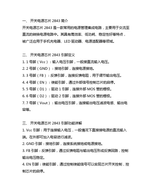
一、开关电源芯片2843简介开关电源芯片2843是一款常用的电源管理集成电路,主要用于交流至直流的转换电源电路中。
其具有高效率、低功耗、稳定性好等特点,被广泛应用于手机充电器、LED驱动器、电源适配器等领域。
二、开关电源芯片2843引脚定义1. 1号脚(Vcc):输入电压引脚,一般接直流输入电压。
2. 2号脚(GND):接地引脚,连接电源接地。
3. 3号脚(FB):反馈引脚,连接反馈电阻,用于调节输出电压。
4. 4号脚(EN):使能引脚,通过外部信号控制芯片的启停。
5. 5号脚(D1):驱动1引脚,连接外部MOS管的栅极。
6. 6号脚(D2):驱动2引脚,连接外部MOS管的栅极。
7. 7号脚(Vout):输出电压引脚,连接输出电压滤波电感、输出电容等。
三、开关电源芯片2843引脚功能详解1. Vcc引脚:用于连接输入电压,一般情况下直接接电源的直流输入端。
在外部可加入电容进行滤波。
2. GND引脚:接地引脚,连接系统接地或电源接地。
3. FB引脚:反馈引脚,通过反馈电阻与输出电压形成反馈回路,控制输出电压稳定。
4. EN引脚:使能引脚,通过控制使能信号可以实现芯片开关控制,控制芯片的启停。
5. D1、D2引脚:驱动引脚,连接外部MOS管的栅极,控制MOS管的导通和截止,实现开关电源的工作。
6. Vout引脚:输出电压引脚,连接输出电压滤波电感、输出电容,输出稳定的直流电压。
四、开关电源芯片2843引脚功能特点1. Vcc引脚输入电压范围广,可适应不同输入电压。
2. GND引脚连接电源接地,提供稳定的接地环境。
3. FB引脚通过连接反馈电阻调节输出电压,稳定输出电压。
4. EN引脚通过使能信号控制芯片的启停,灵活可控。
5. D1、D2引脚通过控制外部MOS管的导通和截止,实现开关电源的工作。
6. Vout引脚输出稳定的直流电压,满足电路需求。
五、结语开关电源芯片2843的引脚定义对于设计和应用该芯片的电子工程师具有重要意义。
开关电源芯片2843引脚定义

开关电源芯片2843引脚定义开关电源芯片2843是一种高度集成的开关电源控制芯片,常用于AC/DC变换器、DC/DC变换器和充电器等电源应用中。
该芯片具有多种保护功能和高效率的特点,能够提供稳定可靠的电源输出。
下面将详细介绍2843芯片的引脚定义与功能,以及相关的应用场景和注意事项。
2843芯片总共具有8个引脚,分别是1脚到8脚。
接下来将逐一介绍每个引脚的定义与功能:1. 1脚(VCC):供电脚,接受外部电源输入(通常是直流电压),一般额定电压为5V。
这个引脚必须连接到正面电源线。
2. 2脚(FB):反馈脚,用于调整输出电压的稳定性。
通过连接一个电阻分压网络到输出端,可以根据需要调节输出电压。
在工作时,该引脚需要连接到一个反馈电阻,以实现稳定的输出电压。
3. 3脚(VSENSE):电流检测脚,用于检测输出电流。
通过连接一个电流感应电阻或传感器,可以实现对输出电流的监测和保护。
4. 4脚(COMP):补偿脚,用于调整芯片的工作频率和稳定性。
通过连接一个电容,可以实现误差放大器的稳定工作。
5. 5脚(GND):接地脚,连接芯片的地线。
这个引脚必须连接到负极地线。
6. 6脚(SS/TR):软启动/关断脚,用于实现软启动和软关断功能。
通过外部电容和电阻的组合,可以调节开关电源的启动和关断时间。
7. 7脚(VDD):供电脚,与1脚相同,接受外部电源输入,通常连接到正极电源线。
8. 8脚(UVLO):欠压锁定脚,用于检测输入电压是否低于一定的阈值。
通过连接一个电阻和电容的组合,可以实现对输入电压的监控和保护。
通过对上述引脚的功能和定义的介绍,可以看出2843芯片可以实现对开关电源的输出电压、输出电流和工作频率的稳定和控制。
它具有多种保护功能,如欠压锁定、过载保护、短路保护等,能够有效地保护电源和负载。
此外,它还具有高效率和低功耗的特点,有助于提高整个电源系统的效率和可靠性。
除了上述基本的引脚定义和功能,以下是一些使用2843芯片时需要注意的事项:1.输入电压范围:2843芯片的输入电压范围通常在7V到30V之间。
TL2842B中文资料

TL3842B
TL3843B
TL3844B
TL3845B
(1) Package drawings, standard packing quantities, thermal data, symbolization, and PCB design guidelines are availableSOIC – D (8 pin)
Reel of 2500 Tube of 75
TL3843BDR-8 TL3844BD-8
Reel of 2500
TL3844BDR-8
Tube of 75
TL3845BD-8
Reel of 2500
TL3845BDR-8
Tube of 75
TL3842BD
The TL284xB and TL384xB series are pin compatible with the standard TL284x and TL384x with the following improvements. The start-up current is specified to be 0.5 mA (max), while the oscillator discharge current is trimmed to 8.3 mA (typ). In addition, during undervoltage lockout conditions, the output has a maximum saturation voltage of 1.2 V while sinking 10 mA (VCC = 5 V).
2
Submit Documentation Feedback
元器件交易网
- 1、下载文档前请自行甄别文档内容的完整性,平台不提供额外的编辑、内容补充、找答案等附加服务。
- 2、"仅部分预览"的文档,不可在线预览部分如存在完整性等问题,可反馈申请退款(可完整预览的文档不适用该条件!)。
- 3、如文档侵犯您的权益,请联系客服反馈,我们会尽快为您处理(人工客服工作时间:9:00-18:30)。
34 V NOM 5 GND
−+
UVLO
5-V VREF EN
8 VREF
RT/CT 4
2.5 V OSC
VREF Good
Logic
Internal Bias
6 OUTPUT
T
2 VFB COMP 1
Error Amplifier
+ −
2R
R
1V
ISENSE 3 A. Pin numbers shown are for the 8-pin D package.
The TL284xB and TL384xB series are pin compatible with the standard TL284x and TL384x with the following improvements. The start-up current is specified to be 0.5 mA (max), while the oscillator discharge current is trimmed to 8.3 mA (typ). In addition, during undervoltage lockout conditions, the output has a maximum saturation voltage of 1.2 V while sinking 10 mA (VCC = 5 V).
Copyright © 2006, Texas Instruments Incorporated
TL284xB, TL384xB HIGH-PERFORMANCE CURRENT-MODE PWM CONTROLLERS
SLVS610A – AUGUST 2006 – REVISED SEPTEMBER 2006
TL284xB, TL384xB HIGH-PERFORMANCE CURRENT-MODE PWM CONTROLLERS
SLVS610A – AUGUST 2006 – REVISED SEPTEMBER 2006
FEATURES
• Low Start-Up Current (<0.5 mA) • Trimmed Oscillator Discharge Current • Current Mode Operation to 500 kHz • Automatic Feed-Forward Compensation • Latching PWM for Cycle-by-Cycle Current
TL2844BDR
Tube of 75
TL2845BD
Reel of 2500
TL2845BDR
TL3842BP
PDIP – P
Tube of 50
TL3843BP TL3844BP
TL3845BP
Tube of 75
TL3842BD-8
Reel of 2500
TL3842BDR-8
Tube of 75
D (SOIC) OR P (PDIP) PACKAGE (TOP VIEW)
COMP 1 VFB 2
ISENSE 3 RT/CT 4
8 VREF 7 VCC 6 OUTPUT
5 GND
D (SOIC) PACKAGE (TOP VIEW)
COMP 1 NC 2
VFB 3 NC 4
ISENSE 5 NC 6
Absolute Maximum Ratings(1)(2)
Limiting
• Internally Trimmed Reference With Undervoltage Lockout
• High-Current Totem-Pole Output Undervoltage Lockout With Hysteresis
• Double-Pulse Suppression
Reel of 2500
TL3842BDR
Tube of 75
TL3843BD
SOIC – D (14 pin)
Reel of 2500 Tube of 75
TL3843BDR TL3844BD
Reel of 2500
TL3844BDR
Tube of 75
TL3845BD
Reel of 2500
TL3845BDR
RT/CT 7
14 VREF 13 NC 12 VCC 11 VC 10 OUTPUT 9 GND 8 POWER GROUND
பைடு நூலகம்
NC − No internal connection
DESCRIPTION/ORDERING INFORMATION
The TL284xB and TL384xB series of control integrated circuits provide the features that are necessary to implement off-line or dc-to-dc fixed-frequency current-mode control schemes, with a minimum number of external components. Internally implemented circuits include an undervoltage lockout (UVLO) and a precision reference that is trimmed for accuracy at the error amplifier input. Other internal circuits include logic to ensure latched operation, a pulse-width modulation (PWM) comparator that also provides current-limit control, and a totem-pole output stage designed to source or sink high-peak current. The output stage, suitable for driving N-channel MOSFETs, is low when it is in the off state.
2
Submit Documentation Feedback
VCC 7
TL284xB, TL384xB HIGH-PERFORMANCE CURRENT-MODE PWM CONTROLLERS
SLVS610A – AUGUST 2006 – REVISED SEPTEMBER 2006
3845B
TL3842B
TL3843B
TL3844B
TL3845B
(1) Package drawings, standard packing quantities, thermal data, symbolization, and PCB design guidelines are available at /sc/package.
TL3843BD-8
SOIC – D (8 pin)
Reel of 2500 Tube of 75
TL3843BDR-8 TL3844BD-8
Reel of 2500
TL3844BDR-8
Tube of 75
TL3845BD-8
Reel of 2500
TL3845BDR-8
Tube of 75
TL3842BD
TL2842BD-8
Reel of 2500
TL2842BDR-8
Tube of 75
TL2843BD-8
SOIC – D (8 pin)
Reel of 2500 Tube of 75
TL2843BDR-8 TL2844BD-8
Reel of 2500
TL2844BDR-8
Tube of 75
TL2845BD-8
S
R
CurrentSense
Comparator
PWM Latch
Submit Documentation Feedback
3
TL284xB, TL384xB HIGH-PERFORMANCE CURRENT-MODE PWM CONTROLLERS
SLVS610A – AUGUST 2006 – REVISED SEPTEMBER 2006
TA –40°C to 85°C
0°C to 70°C
ORDERING INFORMATION
PACKAGE (1)
ORDERABLE PART NUMBER
TL2842BP
PDIP – P
Tube of 50
TL2843BP TL2844BP
TL2845BP
Tube of 75
Reel of 2500
TL2845BDR-8
Tube of 75
TL2842BD
Reel of 2500
TL2842BDR
Tube of 75
TL2843BD
SOIC – D (14 pin)
Reel of 2500 Tube of 75
TL2843BDR TL2844BD
Reel of 2500
Major differences between members of these series are the UVLO thresholds and maximum duty-cycle ranges. Typical UVLO thresholds of 16 V (on) and 10 V (off) on the TLx842B and TLx844B devices make them ideally suited to off-line applications. The corresponding typical thresholds for the TLx843B and TLx845B devices are 8.4 V (on) and 7.6 V (off). The TLx842B and TLx843B devices can operate to duty cycles approaching 100%. A duty-cycle range of 0% to 50% is obtained by the TLx844B and TLx845B by the addition of an internal toggle flip-flop, which blanks the output off every other clock cycle.The TL284xB-series devices are characterized for operation from –40°C to 85°C. The TL384xB-series devices are characterized for operation from 0°C to 70°C.