EngCylCombSIWiebe - SI Wiebe Combustion Model
EATON X10 火警与声音报警系统规格说明书

EATON - SPECIFIER’S GUIDE - FIRE AND VOICE ALARM SYSTEMS SGTEXT ©Februar 2015Die Signaltongeber und Kombi-Signalgeber der Serie X10 sind robuste, langlebige Alarmgeber, die selbst unter den rauesten Umgebungsbedingungen eingesetzt werden können.Die Serie X10 ist für viele verschiedene Anwendungenentworfen, sie ist vielseitig und flexibel einzusetzen, sowohl in Neuanlagen, als auch bei Nachrüstungen. Mit einerReihe von Gehäusegrößen und Kalottenfarben bietet Ihnen die X10 maximale Auswahlmöglichkeiten bei minimalen Artikelpositionen.• 3 Gehäusegrößen Mini 100 dB | Midi 110 dB | Maxi 120 dB •Spannungsbereich:10–60 V DC und 10–30 V AC 115/230 V ACDie X10 bietet eine Reihe einzigartiger Funktionen, so zum Beispiel eine innovative 5-Joule-äquivalente LED-Modul-Blitzleuchte und einen großen Spannungsbereich. Ihre Vielseitigkeit macht sie zur idealen Lösung, wenn es um deutliche und zuverlässige Signalgebung geht. Die X10 signalisiert sicherlich einen Wandel in der industriellen Alarmierung.Hauptmerkmale• IK08 Schlagfestigkeit und DUAL IP Schutzart IP66 und IP69K• 10 Jahre Garantie*•102 Töne erleichtern die Installation und Nachrüstung in einer Vielzahl von industriellen Anwendungen.•6 Kalottenfarben erhältlich, Mini/Midi gesichert durch einen einzigen unverlierbaren Schnellverschluss, Maxi gesichert durch salzbeständige Edelstahlschrauben.• 4 ausbleichsichere Gehäusefarben verfügbar•Bis zu vier Alarmstufen, mit mehreren Alarm- und Steuermöglichkeiten für Wechselstrom- und Gleichstromvarianten.•Modulare LED-Blitzleuchte mit mehreren Funktionen ein/aus; 1/2 Hz (30 FPM) / 1 Hz (60 FPM)• Temperaturbereich -40 °C bis +70 °C• Unverlierbare salzwasserbeständige Edelstahlverschlüsse •M20 vorgebohrte Kabelverschraubungen mit IP69K Blindstopfen als Standard• UV-stabilisiertes Polycarbonat ASA•Niedriger Einschaltstrom mit einer Reihe von dB(A)-LeistungenAlarmierung in industriellen AnwendungenX10 Industrielle SignalgeberFarboptionenX10 GehäuseR1 = Rot (RAL3001)G1 = Dunkelgrau (RAL7012)G2 = Hellgrau (RAL7035)W1 = Weiß (RAL9003)MaxiMidiMiniX10 Modulare KalottenRL = Rote KalotteAL = Gelbe KalotteBL = Blaue KalotteGL = Grüne KalotteML = Magenta KalotteMidiMiniMaxiEATON - SPECIFIER’S GUIDE - FIRE AND VOICE ALARM SYSTEMS SGTEXT ©Februar 2015X10 - MiniX10 - MidiX10 - MaxiNiederspannung DC / AC Netzspannung AC Niederspannung DC / AC Netzspannung AC Niederspannung DC / AC Netzspannung AC 10 V - 60 V DC10 V - 30 V AC 115 V AC 230 V AC 10 V - 60 V DC 10 V - 30 V AC 115 V AC 230 V AC 10 V - 60 V DC 10 V - 30 V AC 115 V AC 230 V AC NUR SIGNALTONGEBER** DIN-Ton, Hohe Lautstärke20 - 35 mA 50 - 85 mA 65 mA 32 mA 35 - 100 mA 75 - 150 mA 69 mA 34 mA 235 - 1600 mA 650 - 2720 mA 160 mA 83 mA KOMBI-SIGNALGEBER**DIN-Ton, Hohe Lautstärke, 1 Hz Blitz35 - 130 mA85 - 235 mA67 mA33 mA45 - 200 mA115 - 400 mA71 mA35 mA250 - 1725 mA705 - 2920 mA168 mA87 mASchalldruckpegel 100 dB110 dB 120 dBSignaltöne 102Stufenalarme bis zu 4Blitzfrequenz 0,5 Hz (30 FPM) / 1 Hz (60 FPM) / Dauerlicht / Aus Betriebstemperatur -40 °C bis +70 °C (Mini/Midi); -30 °C bis +70 °C (Maxi)IP-Schutzarten IP66 und IP69KIK-Stoßfestigkeitsgrad IK08Garantie 10 Jahre *Material UV-stabilisiertes Polycarbonat ASAGehäusefarbe Rot (RAL 3001); Weiß (RAL 9003); Dunkelgrau (RAL 7012); Hellgrau (RAL 7035)Kalottenfarbe Rot, Magenta, Gelb, Klar, Blau, Grün Kabeleinführung Oben 2 x M20 Gewinde-Kabeleinführungen Unten: 1X M20 Gewinde-KabeleinführungAnschlussklemmenbis zu 2,5 mm²Bestell-/ArtikelnummernTechnische DatenWichtiger Hinweis :Wenn Sie einen Kombi-Signalgeber bestellen, müssen Sie zwei Teile bestellen, d.h. das Kombi-Signalgebergehäuse und dieBlitzleuchte, z.B. für einen Midi Kombi-Signalgeber: X10/CE/MDH /R1/10-60VAC-DC und eine Midi Blitzleuchte mit einer gelben Kalotte X10/CE /M2B /ALSerieX10ZulassungCE = IndustriellGehäuseMN = Nur Mini Signaltongeber MD = Nur Midi Signaltongeber MA = Nur Maxi SignaltongeberDie folgenden benötigen eine Blitzleuchte: MNH = Gehäuse für Mini Kombi-Signalgeber MDH = Gehäuse für Midi Kombi-Signalgeber MAH = Gehäuse für Maxi Kombi-Signalgeber Blitzleuchte:M1B = Blitzleuchte für Mini (MNH )M2B = Blitzleuchte für Midi (MDH )M3B = Blitzleuchte für Maxi (MAH )FarbeR1 = Rotes Gehäuse (RAL3001)G1 = Dunkelgraues Gehäuse (RAL7012)G2 = Hellgraues Gehäuse (RAL7035)W1 = Weißes Gehäuse (RAL9003)RL = Rote Kalotte AL = Gelbe Kalotte BL = Blaue Kalotte GL = Grüne Kalotte CL = Klare Kalotte ML = Magenta KalotteSpannungsbereich:10-60 V DC-AC =N iederspannung DC / AC115/230 V AC = Netzspannung ACX10CE MA G210-60 V DC-ACEatonEMEA Hauptverwaltung Route de la Longeraie 71110 Morges, Schweiz Eaton.eu© 2018 EatonAlle Rechte vorbehalten Gedruckt in EMEAVersion 3 November 2018Eaton ist ein eingetragenes Warenzeichen.Alle anderen Warenzeichen sind Eigentum ihrer jeweiligen Inhaber.* Es gelten die Allgemeinen Geschäftsbedingungen.** Der Stromaufnahmebereich basiert auf der Variation der Versorgungsspannung. Eine Änderung der Ton-, Lautstärke- oder der Blitzeinstellungen wirkt sich auch auf die Stromaufnahme aus.。
Orbi路由器配置指南说明书
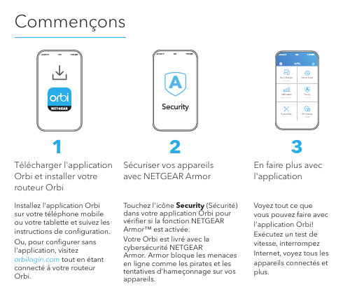
CommençonsInstallez l'application Orbi sur votre téléphone mobile ou votre tablette et suivez les instructions de configuration. Ou, pour configurer sans l'application, visitez tout en étant connecté à votre routeur Orbi.Touchez l'icône Security (Sécurité) dans votre application Orbi pour vérifier si la fonction NETGEAR Armor™ est activée.Votre Orbi est livré avec la cybersécurité NETGEAR Armor. A rmor bloque les menaces en ligne comme les pirates et les tentatives d'hameçonnage sur vos appareils.Voyez tout ce quevous pouvez faire avec l'application Orbi! Exécutez un test de vitesse, interrompez Internet, voyez tous les appareils connectés etplus.Télécharger l'application Orbi et installer votre routeur OrbiSécuriser vos appareils avec NETGEAR Armor 2En faire plus avec l'application3Contenu1Bouton Sync5Port réseau local / réseau étendu (LAN/WAN)2Connecteurd'antenne SMA LTE.Antenne en optionet non incluse6Prised'alimentation3Logement pourcarte nano SIM7Voyantd'alimentation4Ports Ethernet8Bouton deréinitialisationRouteur Orbi (modèle NBR750)CâbleEthernetAdaptateur secteur(varie selon la région)Soutien et communautéVisitez /support pour obtenirdes réponses à vos questions et accéderaux plus récents téléchargements.Vous pouvez également vous référerà notre communauté NETGEAR pourprofiter de conseils utiles à.Pour obtenir des renseignements sur laconformité, y compris la déclaration deconformité de l'UE, visitezhttps:///about/regulatory/.Consultez le document relatif à laconformité réglementaire avant debrancher le bloc d’alimentation.NETGEAR, Inc.350 East Plumeria Drive San Jose, CA 95134, USA © NETGEAR, Inc., NETGEAR et le logo NETGEAR sont des marquesde commerce de NETGEAR, Inc. Toutes les autres marques decommerce sont utilisées à titre de référence uniquement.Juin 2021Information réglementaireet juridiqueDépannageSi vous éprouvez des difficultés avec l'installation, essayez l'une des solutions suivantes :• Redémarrez votre routeur Orbi, puis essayez de nouveau l'installation avec l'application Orbi.• Exécutez l'assistant de configuration à l'aide de l'interface Web. Visitez tout en étant connecté à votre routeur Orbi pour accéder à l'interface Web.• Désinstallez et réinstallez l'application Orbi et réessayez.Pour en savoir plus, visitez /orbihelp.。
贝利莫电子无压依赖特性控制阀说明书
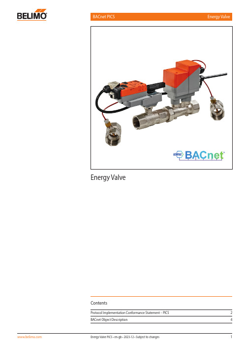
BACnet PICS Energy ValveEnergy ValveContentsProtocol Implementation Conformance Statement – PICS 2 BACnet Object Description 4General information Date26.01.2018Vendor Name BELIMO Automation AGVendor ID423Product Name Energy ValveProduct Model Number EV..R+(K)BAC, EV..R3+BAC, EV..F+(K)BACApplikations Software Version03.02-0000Firmware Revision12.25BACnet Protocol Revision 1.12Product Description Electronic pressure-independent characterisedcontrol valve with energy monitoringBACnet Standard Device Profile BACnet Application Specific Controller (B-ASC)Segmentation capability NoData Link Layer Options MS/TP masterBACnet IP, (Annex J)BACnet IP, (Annex J), Foreign DeviceDevice Address Binding No static device binding supportedNetworking Options NoneCharacter Sets Supported ISO 10646 (UTF-8)Gateway Options NoneNetwork Security Options Non-secure deviceConformance Listed by BTLBACnet Interoperability Building Blockssupported BIBBs Data sharing – ReadProperty-B (DS-RP-B)Data sharing – ReadPropertyMultiple-B (DS-RPM-B)Data sharing – WriteProperty-B (DS-WP-B)Data sharing – COV-B (DS-COV-B)Device management – DynamicDeviceBinding-B (DM-DDB-B) Device management – DynamicObjectBinding-B (DM-DOB-B) Device management – DeviceCommunicationControl-B (DM-DCC-B)BACnet MS/TP Baud rates9’600, 19’200, 38’400, 76’800 (Default: 38’400) Address0...127 (Default: 1)Number of nodes Max 32 (without repeater), 1 full busloadTerminating resistor120 ΩBACnet IP Port open (Default: 47’808)Parameterisation Tool through the integrated webserver !All writeable objects with instance number ≥ 90 are persistent and are not supposed to be written on a regular base.Standard Object Types Supported Objekt type Optional properties Writeable propertiesDevice DescriptionLocationActive COV SubscriptionsMax MasterMax Info FramesProfile Name Object IdentifierObject NameLocationDescriptionAPDU Timeout (1’000…60’000) Number of APDU Retries (0...10) Max Master (1...127)Max Info Frames (1...255)Analog Input [AI]DescriptionCOV IncrementAnalog Output [AO]DescriptionCOV IncrementPresent ValueAnalog Value [AV]Description Present ValueBinary Input [BI]DescriptionActive textInactive TextBinary Valve [BV]DescriptionActive textInactive TextPrresent ValueMulti-state Input [MI]DescriptionState TextMulti-state Output [MO]DescriptionState TextPresent ValueMulti-state Value [MV]DescriptionState TextPresent ValueThe device does not support the services CreateObject and DeleteObject.The specified maximum length of writable strings is based on single-byte characters andsupport up to 252 characters.Service processing The device supports the DeviceCommunicationControl and ReinitializeDevice services. No password is required.A maximum of 5 active COV subscriptions with a lifetime of 1…43‘200 sec. (12 hours) aresupported.Object Name Object Type[Instance]DescriptionCommentStatus_FlagsValues COV Increment AccessDevice Device[Inst.Nr]0…4’194’302Default: 1–WRelPos AI[1]Relative Position in %0...1005R AbsPos AI[2]Absolute Position in degree0...905R SpAnalog_V AI[5]Analog Setpoint in Volt0...10.001R RelFlow AI[10]Relative Flow in %0...1005R AbsFlow_lmin AI[11]Absolute Flow in l/min0...100’0001R AbsFlow_m3h AI[12]Absolute Flow in m3/h0...6000.1R AbsFlow_gpm AI[13]Absolute Flow in gpm0...100’0001R AbsFlow_ls AI[14]Absolute Flow in l/s0...100’0000.1R AbsFlow_lh AI[15]Absolute Flow in l/h0...100’000100R T1_C AI[20]Temperature 1 (remote) in C-10 (1201)T2_C AI[21]Temperature 2 (embedded) in C-10 (1201)DeltaT_K AI[22]Delta Temperature in K0...1301R T1_F AI[25]Temperature 1 (remote) in F14...2481R T2_F AI[26]Temperature 2 (embedded) in F14...2481R DeltaT_F AI[27]Delta Temperature in F0...2661R AbsPower_kW AI[30]Power in kW0...2.147e+610R E_Cooling_kWh AI[31]Cooling Energy in kWh0...2.147e+910R E_Heating_kWh AI[32]Heating Energy in kWh0...2.147e+910R E_Cooling_MJ AI[33]Cooling Energy in MJ0...2.147e+910R E_Heating_MJ AI[34]Heating Energy in MJ0...2.147e+910R AbsPower_kBTUh AI[35]Power in kBTU/h0...2.147e+610R E_Cooling_kBTU AI[36]Cooling Energy in kBTU0...2.147e+910R E_Heating_kBTU AI[37]Heating Energy in kBTU0...2.147e+910R RelPower AI[40]Relative Power in %0...3005R AbsPower_ton AI[45]Power in ton refrigeration0...2.147e+61R E_Cooling_tonh AI[46]Cooling Energy in ton*h0...2.147e+91R E_Heating_tonh AI[47]Heating Energy in ton*h0...2.147e+91R E_CoolReset_kWh AI[50]Cooling Energy in kWh, resettable with BV[31]0...2.147e+91R E_HeatReset_kWh AI[51]Heating Energy in kWh, resettable with BV[32]0...2.147e+91R E_CoolReset_kBTU AI[52]Cooling Energy in kBTU, resettable with BV[31]0...2.147e+91R E_HeatReset_kBTU AI[53]Heating Energy in kBTU, resettable with BV[32]0...2.147e+91RGlycolConcentration AI[60]Glycol concentration in %Measured value or override value from webserver Measured value: 0 (40)Override value: 0 (80)1RErrorState 1)AI[100]Error StateError Sensor T1: Error with remote temperature sensorError Sensor T2: Error with embedded temperature sensorError Flow Sensor: Error with the flow sensorActuator can‘t move: Mechanical overload due to blocked valve, etc.Flow with closed valve: Flow is measured but position of valve is closedAirbubbles: Air bubbles in the hydronic systemFlow not reached: Setpoint cannot be reached within 3min during flow controlPower not realized: Setpoint cannot be reached within 3min during power controlGear disengagement active: Gear disengaged button is pressedReverse flow detected: Reverse flow is detectedMP communication faulty: Internal communication between sensor and actuatorfaultyFreeze warning: Measured temperature & glycol concentration indicate thatgrease ice can build upBit 0: Error Sensor T1Bit 1: Error Sensor T2Bit 2: Error Flow SensorBit 3: Actuator cannot moveBit 4: Flow with closed valveBit 5: Air bubblesBit 6: Flow not reachedBit 7: Power not realizedBit 8: Gear disengagedBit 9: Reverse flow detectedBit 10: MP communicationfaultyBit 11: Freeze warning1RSpAbsFlow_lmin AI[111]Setpoint Absolute Flow in l/min0...100’0001R SpAbsFlow_m3h AI[112]Setpoint Absolute Flow in m3/h0...6000.1R SpAbsFlow_gpm AI[113]Setpoint Absolute Flow in gpm0...100’0001R SpAbsFlow_ls AI[114]Setpoint Absolute Flow in l/s0...100’0000.1R SpAbsFlow_lh AI[115]Setpoint Absolute Flow in l/h0...600100RSpRel AO[1]Setpoint Relative in %The set point is related either to the position, the flow (of Vmax) or the power(of Pmax).See ControlMode for more information → MV[100]0 (100)Default: 01CVmax_lmin AV[90]Maximum Flow Limit in l/min30%Vnom…VnomDefault: Vnom-WVmax_gpm AV [91]Maximum Flow Limit in gpm30%Vnom…VnomDefault: Vnom-WPmax_kW AV [95]Maximum Power Limit in kW0.5%Pnom…PnomDefault: Pnom-WObject Name Object Type[Instance]DescriptionCommentStatus_FlagsValues AccessSpPosReached BI [1]Setpoint Position reached0: No1: YesRSummaryStatus BI [101]Summary StatusSummarizes all status from MI 103 - 1070: OK1: Not OKRRstCoolEnergy BV [31]Reset Cooling EnergySets the Cooling Energy (AI[50] / AI[52]) to zero 0: None1: ResetWRstHeatEnergy BV [32]Reset Heating EnergySets the Heating Energy (AI[51] / AI[53]) to zero 0: None1: ResetWRstErrCount BV [100]Reset Error Counters0: None1: ResetWDeltaT_ MgrStatus MI [102]DeltaT Manager StatusNot selected: dT-Manager deactivatedStandby: dT-Manager activated but not activeActive: dT-Manager activeScaling standby: dT-Manager active with no limitation to the flowScaling active: dT-Manager active with limitation to the flow → AV[108]1: Not selected2: Standby3: Active4: Scaling standby5: Scaling activeRStatusSensor MI [103]Status SensorIndicates informations within the flow sensor and both temperature sensors 1: OK2: Flow sensor not OK3: T1 not OK4: T2 not OKRStatusFlow MI [104]Status FlowReverse flow detected: Energy Valves detected a reverse flowFlow not reached: Setpoint cannot be reached within 3min during flow controlFlow in closed position: Flow is measured but position of valve is closed 1: OK2: Reverse flow detected3: Flow not reached4: Flow in closed positionRStatusMedia MI [105]Status MediaAirbubbles: Airbubbles in the hydronic system. As long as there are airbubblesin the system, position control mode is active, regardless off control modesetting (ControlMode MV[100]).Freeze warning: Measured temperature & glycol concentration indicate thatgrease ice can build up 1: OK2: Airbubbles3: Freeze warningRStatusActuator MI [106]Status ActuatorActuator cannot move: Mechanical overload due to blocked valve, etc.Gear disengaged: Gear disengaged button is pressed 1: OK2: Actuator cannot move3: Gear disengagedRStatusPower MI [107]Status PowerPower not reached: Setpoint cannot be reached within 3min during powercontrol 1: OK2: Power not reachedRObject Name Object Type[Instance]DescriptionCommentStatus_FlagsValues COV Increment AccessPmax_kBTUh AV [96]Maximum Power Limit in kBTU/h0.5%Pnom…PnomDefault: Pnom-WVmax AV [100]Maximum Flow Limit in %30 (100)Default: 100-W Vnom_lmin AV [101]Nominal Volume Flow in l/min Vnom-W Vnom_gpm AV [102]Nominal Volume Flow in gpm Vnom-W SpDeltaT_K AV [103]Setpoint DeltaT in K1 (55)Default: 10-WSpDeltaT_F AV [104]Setpoint DeltaT inF2 (100)Default: 18-WPmax AV [105]Maximum Power Limit in %0.5 (100)Default: 100-W Pnom_kW AV [106]Nominal Power in kW Pnom-R Pnom_kBTUh AV [107]Nominal Power in kBTU/h Pnom-R SpFlow_DeltaT lmin AV [108]Setpoint Flow at DeltaT in l/min0...VnomDefault:Vnom-WSpFlow_DeltaT gpm AV [109]Setpoint Flow at DeltaT in gpm0...VnomDefault:Vnom-WElectronic pressure-independent characterised control valvewith energy monitoringOverride MO [1]Override ControlOverrides setpoint with defined valves. It will change back to None (1) after2 hours.1: None2: Close3: Open4: Vnom5: Vmax6: MotStop7: Pnom8: PmaxDefault: None(1)CControlMode MV [100]Control ModeThis value defines the interpretation of the setpoint 1: Position Control2: Flow Control3: Power ControlDefault: Flow control(2)WDeltaT_Limitation MV [101]DeltaT LimitationDisabled: dT-Manager not activedT-Manager: dT-Manager active with no restriction to flowdT-Manager scaling: dT-Manager active with restriction of flow → AV 108]1: Disabled2: dT-Manager3: dT-Manager scalingDefault: Disabled(1)WSpSource MV [122]Setpoint SourceIf Analog(1) then actuator is controlled by analog signal 0...10 V on wire 3.If Bus(2) then setpoint via bus SpRel AO[1]1: Analog2: BusDefault: Analog(1)W。
维博斯 VBS-2 型应力计 - 说明书

STRESSMETERModel VBS-2APPLICATIONSThe VBS-2 was fi rst developed for monitoring stresschanges in underground coal mi n ing operations. Its usehas since been extended to hard rock and concrete struc-tures. The VBS-2 measures stress or load changes in:• Mines (roof, wall and pillar)• Tunnels (around and within their lining)• Underground storage chambers• Concrete structuresDESCRIPTIONThe VBS-2 stressmeter is composed of a hollow cylindri-cal body sustaining a piano wire across the diameter. Both ends are vacuum sealed with small cans that are electron-beam welded. The body is electroplated to resist corrosion. For excitation and reading purposes, a coil/magnet assembly and a thermistor are encapsu-lated in one of the cans and are connected to an electri-cal cable.A two-part wedge/platen assembly completes the VBS-2 stressmeter. Sitting on the cylindrical body of the stress-meter, this assembly is used to prestress the VBS-2 against the borehole wall at the moment of installation. The wedge/platen assembly can take two confi gurations depending on whether the installation is being made in hard or soft rock. In softer materials such as coal, special wide platens are used to lower the contact stresses on the borehole wall.Stress variations in the host medium will deform the stressmeter, changing the wire tension and thus its reso-nant frequency.FEATURES• Direct measurement of stress changesin solids• Wedge/platen assembly for hard and soft materials• High stress and load sensitivity• Virtually insensitive to temperature changes• Electroplated body to prevent corrosion • Frequency signal easy to process and transmit over long distancesVBS-2 (SR) with wedge and platenSPECIFICATIONSMODEL VBS-2 HR (Hard Rock),VBS-2 SR (Soft Rock)Range 70 MPa (HR), 40 MPa (SR)Sensitivity (depending 14–70 kPa (HR), 7–60 kPa (SR)on rock modulus)Borehole diameter 37–40 mm (HR), 37–39 mm (SR)Operating temperature −20 to +80°C Dimensions 41 × 29 mm (length x diameter)Weight 0.45 kg Thermistor 3kΩ (see model TH-T)Cable IRC-31ACCESSORIES• Installation tools: manual (screw or percussion)• Readout instruments: MB-6T(L), SENSLOGORDERING INFORMATIONPlease specify:• Platen type (hard or soft rock)• Installation depth or cable length • Percussion or screw setting tool • AccessoriesProducts and speci cations are subject to change without notice.E50080-050901© Roctest Limited, 2005.INSTALLATIONThe VBS-2 stressmeter is set in an “E”-size hole (38 mm), preferably diamond drilled, to provide pro-per seating of the gauge against the rock. When per-cussion drilling i s done, it i s o f t he u tmost i mportance to incorporate a reaming shell behind the bit to ob-tain a smooth surface against which the gauge will be wedged.The wedge/platen assembly can be activated from the borehole collar either with a percussion or screw setting tool depending on the depth of installation. In the rst case, depths of 16 meters can be reached. The screw system permits deeper instal lations down to 30 meters.The stressmeter being a uniaxial device, several units may be installed in series to resolve the change in the biaxial stress eld (minimum of 3 measurements) at a particular location. Under good conditions, it is pos-s ible to recover the stressmeter from the borehole.。
Belimo 空调技术文档说明书

T e c h .D o c - 07/14 - S u b j e c t t o c h a n g e . © B e l i m o A i r c o n t r o l s (U S A ), I n c .121Custom Globe Valve Retrofit Solution FormUGSP SeriesDimensions A, B, & C relate to the existing valve stem. Dim A is the stem diameter where it is NOT threaded (Style A), or grooved (Style B). Dim B refers to the length of the threaded region on the valve stem or top region of the grooved stem. Dim C is the actual thread specification for the threaded style stem (1/4-28, 5/16-24, 3/8-24, 7/16-20 & 1/2-20 are typical). Dim C for the grooved style is the measurement of the stem groove height. This information is used to design a stem adapter which will connect the valve stem to the new linkage drive rack. It is important to specify the correct thread pattern, as incorrect data will prevent the stem adapter from attaching to your valve. If you cannot determine the correct thread spec, you can send a nut from the valve stem and we will match the correct specification. In some cases where older valves are concerned, some valve stems must be trimmed in the field to allow attachment of the linkage system. In these cases, a stem adapter is designed to “bite” into the smooth surface of the valve stem itself.Dimensions D1, D2 & D3 are used to determine the height of the linkage assembly required to clear the valves’ full stroke. A minimum of two dimensions are required to manufacture the correct linkage system for your valve. These dimensions also provide the information necessary to determine valve stroke. The maximum stroke from Belimo globe valve retrofit systems is 1.500”.Dimension E refers to the valve bonnet diameter (regardless if threads are present or not). Over time, impurities will react to the bonnet threads and corrode them to the point where they no longer meet the original thread specification. Because of this, we manufacture slip fit collars designed to slide over the bonnet threads, and locking setscrews are provided which “bite” into the original threads. All retrofit systems are designed to work with the raw valve body and do not account for previous actuation components which must be removed from the valve body before attaching the new linkage system.Dimension F refers to the thread specification on threaded bonnets, and refers to the minor diameter on slip on bonnets (Landis type). This information helps us determine the length of the locking devices required to hold the collar onto the bonnet.Dimensions G & H are used to determine working height of the bonnet region of your globe valve, while Dim I is used in calculating the minimum ID of the collar that will fit over the packing nut. Additionally, information about the environment and process in which this linkage system will be utilized should be provided.All the requested information contained on this form is required to guarantee the complete, perfect fit of your retrofit system. Keep in mind that retrofit kits are designed with close-tolerance components which afford the most efficient linkage systems. Measurements rounded to the nearest 1/8 or 1/16 inch will not perform as well as a kit designed around careful measurements using proper equipment. Our designs are typically +.005” tolerance.Required Tools - calipers, thread gauge, and retrofit formWe will do our best to provide a linkage system designed around your specifications and measurements. However, we cannot be held responsible for linkages which do not fit as a result of incorrect data given to Belimo. We will re-work components which do not fit properly for a nominal fee. To reduce the possibility of incorrect linkage solutions, we respectfully request that you fill out the retrofit form completely and forward thatinformation with your order. This will serve as a double check between your valve and the actuator/linkage package designed for your application.Actuation, weather shields and linkages cannot be pre-assembled at the Belimo factory prior to your receipt. The linkages are designed to be attached onto the valve body first, then optional weather shields, and finally actuation products.Close-off pressures are calculated using actuator torque, valve stroke, and valve area. Other factors may affect the rated close-off pressures, including flow rates, system maintenance schedules, chemicals used in the shot feeder process, vicinity to pumps, condition of valve stem seals, and assembly of linkage material in the field.Valves that are being considered for retrofit of actuation should be analyzed for their life expectancy before the retrofit has taken place. Valves that leak through stem seals or casings will continue to leak with the new linkage system in place, maybe even more so. Rebuilding the packing on these valves may be more costly than replacing the valves themselves. In some instances, older valve stem heights will require field modifications to the valve in order to utilize the retrofit kit. Belimo takes no responsibility for the operation of these valves after they have been modified.Instructions for Completing this FormT e c h .D o c - 07/14 - S u b j e c t t o c h a n g e . © B e l i m o A i r c o n t r o l s (U S A ), I n c .Custom Globe Valve Retrofit Solution FormUGSP SeriesFAIL SAFE: FAIL POSITION: VOLTAGE _____ACTUATOR 2 WAY/3 WAY:VALVE SIZE:MEDIA TEMP:MEDIA TYPE:SYSTEM PRESSURE:VALVE MANUFACTURE:VALVE SERIES:VALVE MODEL:VALVE TAG/LOCATION:QUANTITY:COMPANY:JOB NAME:PO#:PHONE:EMAIL:NOTE: THIS INFORMATION WILL BE UTILIZED IN THE FABRICATION OF A CUSTOM LINKAGE SYSTEM FOR YOUR VALVE REQUIREMENT; THEREFORE, IT IS ESSENTIAL THAT THE ABOVE DIMENSIONS BE FURNISHED WITH READINGS TAKEN TO THE NEAREST .001". ANY ERRONEOUS DIMENSIONS FURNISHED WHICH RESULT IN IMPROPER FIT OF THIS LINKAGE SYSTEM ARE NOT THE RESPONSIBILITY OF BELIMO AIRCONTROLS. ANY REWORK REQUIRED WILL RESULT IN AN EXTRA CHARGE.CUSTOM KITS ARE DESIGNED TO YOUR UNIQUE SPECIFICATIONS AND ARE NOT RETURNABLE.COMPANY CONTACT/DIMENSIONS PROVIDED BY: ____________________________________________________________________ DATE: ___________________T e c h .D o c - 07/14 - S u b j e c t t o c h a n g e . © B e l i m o A i r c o n t r o l s (U S A ), I n c .158Custom Butterfl y Valve Retrofi t Solution FormUFSP SeriesPlease keep in mind that all dimensions should be taken with ALL original actuation and hardware components removed from the valve body.Examples of dimensions A & B (Dim A and Dim B) relate to the TOP mounting holes on the butterfl y valve body. These holes are usually arranged onthe body in either an “X” pattern (MOUNT STYLE 1), or a cross pattern (MOUNT STYLE 2). This information is entered on the UFSP Series Butterfl y Valve Retrofi t Form in the MOUNT STYLE section. The length of the valve stem sticking out of the top of the valve body is recorded under Dim C . The TOP mounting holes are usually drilled through the top fl ange, but sometimes are threaded. Enter this information on the form next to the mount style information previously recorded.Next is the valve stem data. The fi ve styles of valve stems cover 98% of the butterfl y valves ever produced. Examine the valve being retrofi tted to establish which shaft style matches the diagrams above. Use caution when recording these dimensions. Careless use of calipers will result in a sloppy and possibly dysfunctional linkage system. Dim D refers to the valve stem diameter and should be measured at several points up and down as well as around the stem itself. Dim E refers to the length of the drive surface available, whether it be a key, fl atted surface, or the distance a drive hole is from the top of the stem. There are two types of keys (Keyway-Shaft Style 4 and Woodruff Key-Shaft Style 5). Please select the key size as noted in the column “For Shaft Style 4 & 5”. Dim F refers to the width of the drive surface. This is the most critical dimension for correct linkage operation. Please measure accordingly. In addition, we require information about the environment and process in which this linkage system will be utilized.The form must be completed in its entirety to guarantee the complete, perfect fi t of your retrofi t system. Keep in mind that retrofi t kits are designed with close-tolerance components which afford the most effi cient linkage system for the facility. Measurements rounded to the nearest 1/8 or 1/16 inch will not perform as well (sometimes not at all) as a kit designed around careful measurements using proper equipment. Our designs are typically +.005” tolerance.Required tools - calipers and retrofi t form.DISCLAIMERWe will do our best to provide a linkage system designed around your specifications and measurements. However, we cannot be held responsible for linkages which do not fit as a result of incorrect data given to Belimo. We will re-work components which do not fit properly for a nominal fee. To reduce the possibility of incorrect linkage solutions, we respectfully request that you fill out the retrofit form completely and forward thatinformation with your order. This will serve as a double check between your valve and the actuator/linkage package designed for your application.Actuation, weather shields and linkages cannot be pre-assembled at the Belimo factory prior to your receipt. The linkages are designed to be attached onto the valve body first, then optional weather shields, and finally actuation products.Close-off pressures are calculated using actuator torque, valve stroke, and valve area. Other factors may affect the rated close-off pressures,including flow rates, system maintenance schedules, chemicals used in the shot feeder process, vicinity to pumps, condition of valve stem seals, and assembly of linkage material in the field.Valves that are being considered for retrofit of actuation should be analyzed for their life expectancy before the retrofit has taken place. Valves that leak through stem seals or casings will continue to leak with the new linkage system in place, maybe even more so. Rebuilding the packing on these valves may be more costly than replacing the valves themselves. In some instances, older valve stem heights will require field modifications to the valve in order to utilize the retrofit kit. Belimo takes no responsibility for the operation of these valves after they have been modified.Instructions for Completing this FormT e c h .D o c - 07/14 - S u b j e c t t o c h a n g e . © B e l i m o A i r c o n t r o l s (U S A ), I n c .FAIL SAFE: FAIL POSITION: VOLTAGE_____ACTUATOR DIM F:DIM E:DIM D:SHAFT STYLEDIM G:DIM H:2 WAY/3 WAY:VALVE SIZE:MEDIA TEMP:MEDIA TYPE:VALVE MANUFACTURE:VALVE SERIES:VALVE MODEL:VALVE TAG/LOCATION:COMPANY:JOB NAME:PO#:PHONE:CUSTOM KITS ARE DESIGNED TO YOUR UNIQUE SPECIFICATIONS AND ARE NOT RETURNABLE.COMPANY CONTACT/DIMENSIONS PROVIDED BY: ____________________________________________________________________ DATE: ___________________T e c h .D o c - 07/14 - S u b j e c t t o c h a n g e . © B e l i m o A i r c o n t r o l s (U S A ), I n c .165Ball valves with-out a mounting fl ange are typically not designed for installing actuation, therefore the valve design may not support modulation outside of manual usage. Belimo does not recommend retrofi tting these types of ball valves.All dimensions should be taken with ALL original actuation and hardware components removed from the valve body.An example using Mounting Style 3: Dimensions A & B (Dim A and Dim B ) relate to the TOP mounting holes on the ball valve body. These holes are usually arranged on the body in a “X” pattern (MOUNT STYLE 3). This information is entered on the UBSP Series Ball Valve Retrofi t Form in the MOUNT STYLE section. The length of the valve stem sticking out of the top of the valve body is recorded under Dim D and E . The TOP mounting holes are usually drilled through the top fl ange, but sometimes are threaded. Enter this information on the form next to the mount style information previously recorded.MOUNT STYLE 3: Dimensions A & B (Dim A and Dim B ) relate to the TOP mounting holes on the ball valve body. These holes are usually arranged on the body in a “X” pattern (MOUNT STYLE 3). This information is entered on the UBSP Series Ball Valve Retrofi t Form in the MOUNT STYLE section. The length of the valve stem sticking out of the top of the valve body is recorded under Dim D and E . The TOP mounting holes are usually drilled through the top fl ange, but sometimes are threaded. Enter this information on the form next to the mount style information previously recorded.STEM STYLE: Examine the valve being retrofi tted to establish which stem style matches the diagrams above. Use caution when recording these dimensions. Dim H refers to the valve stem diameter and should be measured at several points up and down as well as around the stem itself. Dim E refers to the length of the drive surface available, whether it is a key or fl atted surface. Dim F refers to the width of the drive surface or the distance across the fl ats. This is the most critical dimension for correct linkage operation. Please measure accordingly. Lastly please specify thedesired actuator orientation in reference to the valve body using the ports as reference, i.e. over the “A” port etc. We have also includes an ISO-5211 standard dimension chart for reference. If the valve is labeled please specify its “F” number so that we may confi rm the dimensions per the ISO spec.In addition, we require information about the environment and process in which this linkage system will be utilized. As well as the frequency of use the current actuator runs. This will help to ensure the longevity of the new linkage and actuator. Having the prior actuator spec and model will help.The form must be completed in its entirety to guarantee the complete, perfect fi t of your retrofi t system. Keep in mind that retrofi t kits are designed with close-tolerance components which afford the most effi cient linkage systems. Measurements rounded to the nearest 1/8 or 1/16 inch will not perform as well (sometimes not at all) as a kit designed around careful measurements using proper equipment. Our designs are typically +.005” tolerance.Required tools - calipers and retrofi t form. We will do our best to provide a linkage system designed around your specifications and measurements. However, we cannot be held responsible for linkages which do not fit as a result of incorrect data given to Belimo. We will re-work components which do not fit properly for a nominal fee. To reduce the possibility of incorrect linkage solutions, we respectfully request that you fill out the retrofit form completely and forward thatinformation with your order. This will serve as a double check between your valve and the actuator/linkage package designed for your application.Actuation, weather shields and linkages cannot be pre-assembled at the Belimo factory prior to your receipt. The linkages are designed to be attached onto the valve body first, then optional weather shields, and finally actuation products.Close-off pressures are calculated using actuator torque, valve stroke, and valve area. Other factors may affect the rated close-off pressures, including flow rates, system maintenance schedules, chemicals used in the shot feeder process, vicinity to pumps, condition of valve stem seals, and assembly of linkage material in the field.Valves that are being considered for retrofit of actuation should be analyzed for their life expectancy before the retrofit has taken place. Valves that leak through stem seals or casings will continue to leak with the new linkage system in place, maybe even more so. Rebuilding the packing on these valves may be more costly than replacing the valves themselves. In some instances, older valve stem heights will require field modifications to the valve in order to utilize the retrofit kit. Belimo takes no responsibility for the operation of these valves after they have been modified.Instructions for Completing this FormT e c h .D o c - 07/14 - S u b j e c t t o c h a n g e . © B e l i m o A i r c o n t r o l s (U S A ), I n c .Custom Ball Valve Retrofi t Solution FormFAIL SAFE: FAIL POSITION: ACTUATOR ORIENTATION:ACTUATOR DIM H:DIM G:DIM F:STEM STYLEDIM I:DIM J:2 WAY/3 WAY:VALVE SIZE:MEDIA TEMP:MEDIA TYPE:SYSTEM PRESSURE:VALVE MANUFACTURE:VALVE SERIES:VALVE MODEL:VALVE TAG/LOCATION:QUANTITY:COMPANY:JOB NAME:PO#:PHONE:EMAIL:NOTE: THIS INFORMATION WILL BE UTILIZED IN THE FABRICATION OF A CUSTOM LINKAGE SYSTEM FOR YOUR VALVE REQUIREMENT; THEREFORE, IT IS ESSENTIAL THAT THE ABOVE DIMENSIONS BE FURNISHED WITH READINGS TAKEN TO THE NEAREST .001". ANY ERRONEOUS DIMENSIONS FURNISHED WHICH RESULT IN IMPROPER FIT OF THIS LINKAGE SYSTEM ARE NOT THE RESPONSIBILITY OF BELIMO AIRCONTROLS. ANY REWORK REQUIRED WILL RESULT IN AN EXTRA CHARGE.CUSTOM KITS ARE DESIGNED TO YOUR UNIQUE SPECIFICATIONS AND ARE NOT RETURNABLE.COMPANY CONTACT/DIMENSIONS PROVIDED BY: ____________________________________________________________________ DATE: ___________________B。
SEKUSEPT EASY Combi Pack 说明书

Sekusept Easy Combi Pack®VLOEIBAAR HIGH LEVEL DESINFECTIE-MIDDEL VOOR INSTRUMENTARIUM\Maximale reiniging \Veilig voor materialen \Volledig spectrumVolledig spectrumEigenschappenEcolab BVBA/SPRLNoordkustlaan 16 C -1702 Groot-BijgaardenWetenschappelijk dossier en MSDS-fiche zijn verkrijgbaar op aanvraag.VERPAKKING / REFERENTIEVoordelenTOEPASSINGDoeltreffende desinfectieGoede compatibiliteitGEBRUIKSAANWIJZINGSAMENSTELLINGProducten ServiceGarantieToebehoren Maximale reiniging/desinfectie, ook bij sterk vervuilde instrumenten, korte inwerktijdVeilig voor materialenBactericide, sporicide, gistdodend, virucideGebruiksvriendelijkTeststrookjes ter controle van de oplossingSekusept Easy :Waterstofperoxide, perazijnzuur, organische zuren en neutralisator Sekusept Activator : Alkali, fosfatenVoor de desinfectie na reiniging van medisch instrumentarium zoals flexibele endoscopen, instrumenten uit chroom-nikkel en rubber/plastic toebehoren voor anesthesie, urologie en chirurgie.NIET geschikt voor medisch instrumentarium vervaardigd uit messing of koper of reeds beschadigde instrumenten of endoscopen.Aanmaken van een 10 L oplossing :Voeg 1 flacon Sekusept Easy toe aan 6 L water.Voeg vervolgens 1 flacon Sekusept Activator toe aan de oplossing en roer om.Vul bij met water (max. 30°C) tot een totale hoeveelheid van 10 L.Uw oplossing is klaar voor gebruik. De instrumenten onderdompelen in de oplossing en na 15 min. deinstrumenten uit de oplossing nemen en met water (minstens drinkwater-kwaliteit) afspoelen.De oplossing dagelijks verversen.Sekusept E asy Combi Pack bestaande uit :10 L oplossing –ref. : 3020470Sekusept Easy -Verp. : 4 x 450 ml Sekusept A ctivator -Verp. : 4 x 420 ml 5 L oplossing –ref. : 3028780Sekusept Easy -Verp. : 6 x 225 ml Sekusept Activator -Verp. : 6 x 210 ml Teststrookjes voor Sekusept Easy :Verp. : 4 x 50 stuks –ref. : 3007370+VLOEIBAAR HIGH LEVEL DESINFECTIE-MIDDEL VOOR INSTRUMENTARIUMINFORMATIEEcolab BVBA/SPRLNoordkustlaan 16 C -1702 Groot-BijgaardenProducten ServiceGarantieToebehoren +VLOEIBAAR HIGH LEVEL DESINFECTIE-MIDDEL VOOR INSTRUMENTARIUM15 minSporicide (schone omstandigheden) –EN draft CEN/TC216/WG1 N1765 min Bactericide -EN 104015 min Virucide –EN 144765 min M terrae (schone omstandigheden) –EN 14348 5 min Fungicide (gisten) –EN 1275 1 min Bactericide (schone omstandigheden) –EN 13727InwerktijdWerkingsspectrum。
三星电子数码商品说明书
Samsung ER-5200 and ER-5215 and ER-5240 operating and programming SPANISH ManualCaja Registradora Electrónica ER 5200/40/15Manual de Operación yProgramaciónTodas las especificaciones de este manual están sujetas a cambios sin previo avisoContenidoIntroducción 1 Sobre la Serie ER-5200 (1)Desembalaje (1)Instalación del Papel (2)Características Básicas y Funciones (6)Hardware Standard (6)Hardware Opcional (6)Características de Software (6)Visor (7)Cerradura de Control (11)Teclados (12)Operaciones 17 Descripción de las Teclas de Función (17)Asignación de Empleados (21)Asignación Directa (21)Asignación por Código (21)Tiquet Sí/No (22)Registro de PLUs (23)Entrada de PLU abierto del Teclado (24)Entrada de PLU prefijado del Teclado (24)Entrada repetida de PLU del Teclado (25)Multiplicación de PLU del Teclado (26)Multiplicación Decimal de PLU del Teclado (27)Precio Partido de PLU del Teclado (28)PLU del teclado de Venta única (29)Entrada de PLU abierto por Código (30)Entrada de PLU prefijado por Código (30)Multiplicación de PLU por Código (31)Multiplicación Decimal de PLU por Código (32)Precio Partido de PLU por Código (32)Operaciones de Anulación y Corrección (33)Anula Última (33)Corrección (34)Retorno (35)Llave VOID (Anulación de Transacción) (36)Anula Tíquet (37)Operaciones de Cobro (38)Efectivo (38)Cheque (39)Crédito (40)Cobro Partido (41)Cambio Posterior (41)Interrupción de Empleados (42)Modo de Entrenamiento (43)Caja Registradora ER-5200/40/15 iNúmero de Referencia (44)Apertura de Cajón (44)Recibido a Cuenta (45)Pagos (46)Conversión de Divisas (47)Funciones de Manager 48 Introducción (48)Declaración de Caja (49)Informes de Sistema (50)Realizar un Informe – Instrucciones Generales (50)Tabla de Informes (51)Modo de Pc Online (52)Listado de Configuración de Memoria (52)Configuración de Memoria (53)Borrado de Totales (54)Borrado de Gran Total (54)Borrado de PLUs (54)Información de Eprom (54)Programación 55 Programación por Defecto (55)Asignación de Teclas de Función (56)Programación de IVAs (58)Programación de Porcentaje de IVA (59)Programación de PLUs (60)Programa 100 – Programación del estado de PLU (61)Programa 150 – Asignación de Grupo de PLU (64)Programa 200 – Programación de Precio/Límite de PLU (65)Programa 250 – Programación de Stock de PLU (66)Programa 300 – Programación de la descripción de PLU (67)Programa 350 – Programación de PLU Conectado (70)Programa 400 – Borrado de PLUs (71)Programa 450 – Programación de Ofertas de PLU (72)Programación de Opciones de Sistema (73)Tabla de Opciones de Sistema (74)Programación de Opciones de Impresión (77)Tabla de Opciones de Impresión (78)Programación de Teclas de Función (82)Programa 70 – Opciones de Teclas de Función (83)Programa 80 – Descripción de Teclas de Función (84)Programa 90 – Límite de Teclas de Función (85)SUMA CHEQUE – Programa de Tecla Función (86)ANULA TIQUET – Programa de Tecla de Función (87)TOTAL – Programa de Tecla de Función (88)CREDITO1-8 – Programa de Teclas de Función (89)CHEQUE – Programa de Tecla de Función (90)CANJEO CHEQUE – Programa de Tecla de Función (91)ENDORSO CHEQUE – Programa de Tecla Función (92)FACTURA # - Programa de Tecla de Función (93)DIVISAS - Programa de Teclas de Función (94)SERVI-AUTO/TOMAR EN LOCAL/PARA LLEVAR – Programa de Teclas deFunción (95)ii Caja Registradora ER-5200/40/15ANULA ÚLTIMA – Programa de Tecla de Función (96)SUBTOTAL CUPON – Programa de Tecla de Función (96)COBRO CUPON – Programa de Tecla de Función (97)COMENSALES – Programa de Tecla de Función (98)NIVEL1-2 – Programa de Teclas de Función (98)#/CAJON – Programa de Tecla de Función (99)RETORNO – Programa de Tecla de Función (100)MODIFICADOR 1-5 – Programa de Teclas de Función (101)PAGO MESAS – Programa de Tecla de Función (102)SALDO – Programa de Tecla de Función (102)INVITACION – Programa de Tecla de Función (103)PAGOS 1-3 – Programa de Tecla de Función (104)IMPRIME FACTURA – Programa de Tecla de Función (105)RECIBIDO A CUENTA 1-3 – Programa de Teclas de Función (106)BALANZA – Programa de Tecla de Función (107)SERVICIO – Programa de Tecla de Función (108)SUBTOTAL – Programa de Tecla de Función (109)MESA – Programa de Tecla de Función (109)TARA – Programa de Tecla de Función (110)EXENTO IVA – Programa de Tecla de Función (111)PROPINA – Programa de Tecla de Función (112)VALIDACION – Programa de Tecla de Función (113)CORRECCION – Programa de Tecla de Función (114)MERMA – Programa de Tecla de Función (115)%1- %5 - Programa de Teclas de Función (116)Programación de Empleados (118)Programa 800 – Programación de Código Secreto (119)Programa 801 – Asignación de Cajón y Programación de Empleado deEntrenamiento (119)Programa 810 - Programación de Descripción de Empleado (120)Programación de Ofertas (121)Programa 600 – Programación de Cantidad (122)Programa 601 – Programación de Precio (122)Programa 610 – Programación de Descripción de Oferta (123)Programación de Grupos (124)Programaciones Varias (126)Programación de Teclas de Macro (126)Programación de Descripciones (127)Programación de los Códigos NLU (132)Programación de Límite de Efectivo en Cajón (133)Programación de Límite de Cambio de Cheque (134)Programación de la Fecha y la Hora (135)Programación de Peso de Tara (136)Programación de Número de Máquina (137)Programación de las opciones de los Puertos RS-232 (138)Listados de Programación (140)Caja Registradora ER-5200/40/15 iiiThis is a “Table of Contents preview” for quality assuranceThe full manual can be found at /estore/catalog/ We also offer free downloads, a free keyboard layout designer, cable diagrams, free help andsupport. : the biggest supplier of cash register and scale manuals on the net。
NETGEAR Orbi路由器和卫星设置指南说明书
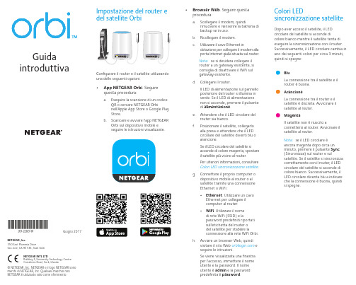
. Seguirequesta procedura:a. Eseguire la scansione di un codiceQR o cercare NETGEAR Orbinell'Apple App Store o Google Play Store.b. Scaricare e avviare l'app NETGEAROrbi sul dispositivo mobile e seguire le istruzioni visualizzate.• Browser Web . Seguire questaprocedura:a. Scollegare il modem, quindirimuovere e reinserire la batteria di backup se in uso.b. Ricollegare il modem.c. Utilizzare il cavo Ethernet indotazione per collegare il modem alla porta Internet gialla situata sul router.Nota: se si desidera collegare il router a un gateway esistente, si consiglia di disattivare il WiFi sul gateway esistente.d. Collegare il router.Il LED di alimentazione sul pannello posteriore del router si illumina in verde. Se il LED di alimentazione non si accende, premere il pulsante di alimentazione .e. Attendere che il LED circolare delrouter sia bianco.f. Posizionare il satellite, collegarloalla presa e attendere che il LED circolare del satellite diventi blu o arancione.Se il LED circolare del satellite si accende di colore magenta, spostare il satellite più vicino al router.Per ulteriori informazioni, consultare Colori LED sincronizzazione satellite .g. Connettere il proprio computer odispositivo mobile al router o al satellite tramite una connessione Ethernet o WiFi:• Ethernet . Utilizzare un cavo Ethernet per collegare il computer al router. • WiFi . Utilizzare il nome di rete WiFi (SSID) e lapassword predefiniti riportati sull'etichetta del router o del satellite per stabilire la connessione alla rete WiFi Orbi.h. Avviare un browser Web, quindivisitare il sito Web e seguire le istruzioni.Se viene visualizzata una finestra per l'accesso, immettere il nome utente e la password. Il nome utente è admin e la password predefinita è password .BluLa connessione tra il satellite e il router è buona. ArancioneLa connessione tra il router e il satellite è discreta. Avvicinare il satellite al router.MagentaIl satellite non è riuscito aconnettersi al router. Avvicinare il satellite al router.Nota: se il LED circolare è ancora magenta dopo circa un minuto, premere il pulsante Sync (Sincronizza) sul router e sulsatellite. Se il satellite si sincronizza correttamente con il router, il LED circolare del satellite si accende di colore bianco. Successivamente, il LED circolare diventa blu a indicare che la connessione è buona, quindi si spegne.Dopo aver acceso il satellite, il LED circolare del satellite si accende dicolore bianco mentre il satellite tenta di eseguire la sincronizzazione con il router. Successivamente, il LED circolare cambia in uno dei seguenti colori per circa 3 minuti, quindi si spegne:Colori LEDsincronizzazione satelliteNETGEAR INTL LTDBuilding 3, University Technology Centre Curraheen Road, Cork, IrlandaNETGEAR, Inc.350 East Plumeria DriveSan Jose, CA 95134, Stati Uniti© NETGEAR, Inc. NETGEAR e il logo NETGEAR sono marchi di NETGEAR, Inc. Qualsiasi marchio non NETGEAR è utilizzato solo come riferimento.Giugno 2017LED circolare (non mostrato nell'immagine)Pulsante Sync (Sincronizza) (utilizzato anche per la connessione WPS)Porte Internet (il satellite Orbi non include una porta Internet)Porte EthernetSupportoGrazie per aver acquistato questo prodotto NETGEAR. Visitare il sito Web/support per registrare il prodotto, ricevere assistenza, accedere ai download e ai manuali per l'utente più recenti e partecipare alla nostra community. Consigliamo di utilizzare solo risorse di assistenza NETGEAR ufficiali.Per consultare la Dichiarazione diconformità UE attuale, visitare la pagina: /app/answers/detail/a_id/11621/.Per informazioni sulla conformità alle normative, visita il sito Web all'indirizzo/about/regulatory/.Prima di collegare l'alimentazione, consultare il documento relativo alla conformità normativa.Panoramica sul router OrbiRouter Orbi (modello RBR50)Satellite Orbi (modello RBS50)Cavo EthernetAlimentatori (2)(varia in base alla regione)Panoramica sul satellite OrbiContenuto della confezione 2134128218Porta USBPulsante e LED di alimentazione Connettore di alimentazione CC Pulsante di ripristino5678。
- 1、下载文档前请自行甄别文档内容的完整性,平台不提供额外的编辑、内容补充、找答案等附加服务。
- 2、"仅部分预览"的文档,不可在线预览部分如存在完整性等问题,可反馈申请退款(可完整预览的文档不适用该条件!)。
- 3、如文档侵犯您的权益,请联系客服反馈,我们会尽快为您处理(人工客服工作时间:9:00-18:30)。
Burned Fuel % at Duration Start Burned Fuel % ak Model Selection One of the following choices: • • • ign indicates that the user is not modeling knock or pre-ignition. standard indicates that the user wishes to use the knock models as defined in the ' EngCylKnock' reference object. standard-lastcycle indicates that the user wishes to use the knock models as defined in the ' EngCylKnock' reference object, but the calculation will be made for only the last cycle of each case. This option is recommended when the simulation is at steady state, the attributePost-Knock Combustion is off, and the attribute End Gas Zones is set to Multi-Zone in the 'EngCylKnock' reference object because the results of the knock model will not affect the rest of the model , and the calculation of knock will be computationally expensive. This option should not be used when the output of knock is used in a feedback control system (e.g., to control spark timing). This option cannot be used when the Post-Knock Comb Post-Knock Combustion is on, as that will affect the results and produce an incorrect result. user indicates that the user has created a knock model that should be called during combustion. (See Chapter 1 for more information about user models.)
Duration (def = 10% to 90%)
Wiebe Exponent
Options
Number of Temperature Zones Must be one of the following two choices: • two-temp indicates that temperature and composition will be independently calculated for the burned and unburned gases in the cylinder chamber. This option is recommended for most simulations and must be used to achieve meaningful NOx results with NOx Reference Object below. single-temp specifies a single-zone combustion model. This option is typically only chosen to maintain consistent results with other analyses that might assume only one temperature zone such as routines used to calculate heat release from measured cylinder pressure.
ENGINE (GT−POWER) REFERENCE TEMPLATES : EngCylCombSIWiebe − SI Wiebe Combustion Model
EngCylCombSIWiebe - SI Wiebe Combustion Model
This object imposes the combustion burn rate for spark-ignition engines using a Wiebe function. It can be used with any type of injection. If at any instant the specified cumulative combustion exceeds the specified injected fuel fraction for a direct-injected SI ( DISI) engine, the combustion rate will be limited by the amount of fuel available. Please note that if the imposed combustion rate starts before the cycle-start, all fuel prescribed to be burned prior to cycle-start will be burned on the second timestep of the cycle (resulting in a "spike" in the burn rate). An Excel file named WiebeComb.xls is included in the installation directory of GT-SUITE and is useful in determining the Wiebe constants. The combustion spreadsheet has a feature to match the Wiebe constants to a heat release rate that has been calculated from measured cylinder pressure using the 'EngBurnRate' template. However, note that the 'EngCylCombProfile' reference object can be used to directly input the burn rate calculated from cylinder pressure, and so it is not necessary to match the Wiebe parameters to measured combustion data. Please see the Engine Performance Manual section on “Calculating Burn Rate from Measured Cylinder Pressure” for details.
Air Burning Enhancement Factor
Burned Fuel % at Anchor Angle
Percentage burn point used for the Anchor Angle ("def"=50). This point must always be 0.1% higher than the duration start and 0.1% lower than the duration end to obtain a profile that will satisfactorily fit the defined points. Percentage burn point that signals the start of the Burn Duration attribute ("def"=10). Percentage burn point that signals the end of the Burn Duration attribute ("def"=90). This point must always be 10% higher than the duration start to obtain a profile that will satisfactorily fit the defined points.
Main
Anchor Angle (def = 50% Burn) Angle "anchoring" the Wiebe curve to TDC or the name of a dependency reference object specifying the angle. The specified angle is the number of crank angle degrees between TDC and typically the 50% combustion point of the Wiebe curve. The attribute Burned Fuel % at Anchor Angle below may optionally be used to change the burn point in the Wiebe curve from 50%. (Typical values are 5 to 12 degrees after TDC.) Duration of Wiebe combustion curve or the name of a dependency reference object specifying the burn duration. The duration by default excludes the first 10% and last 10% of the total combustion duration, but the attributes in the Options folder below may be used to set the burn points where the duration is measured. (Typical values are 25 to 35 degrees.). Wiebe curve exponent or the name of a dependency reference object. ("def"=2.0)