2014-09 DL K supply list
Autodesk Fabrication CAMduct 2014 Service Pack 3 改

Autodesk®Fabrication CAMduct™ 2014Service Pack 3 Enhancement ListImprovements made in Service Pack 3 build 3.02.706:Pattern Improvements∙CID 324 - Improved Initial Makepat units for Imperial configuration where they were previously showing as metric.∙CID 535 - Improved Draw Type Options.∙CID 64 - Improved Development.∙CID 1127 - Improved Collar Developments.∙CID 1142 - Improved Development.∙CID 1148 - Improved holes on Development.∙CID 854 - Improved faces visibility when Bottom Radius set to 0.∙Improved Fabrication items by allowing functions to be used in calculated dims.∙Improvement made to straight duct patterns as seams were not being removed with the holes.∙Improvements to Bend insulation faces.∙Stability improvement when loading jobs with dampers.Productivity Improvements∙Improved cloud nesting to restrict processing items from being nested on the context menu.∙Improved cloud nesting to set item statuses to prevent processed items from being selected for nesting.∙Improved Linear Nest part lengths to report the correct imperial units.General Usability Improvements∙Improvement to nesting to include slits on all duplicate parts when slits are required.∙Stability improvement when using delete NC.∙Improvements made to nesting so that v-notches are cut true to the development profile.∙Improvement made to installed machines, when no machines are listed to remember newly created entries.∙Improved selection drop down lists to stop scrolling when selections are made.∙Enhancements to data views to allow Window Selections.∙Improvement to nesting to include slits on all duplicate parts when slits are required.∙Improved Dynamic Holes Developments.∙Improvements made to Dynamic Holes when branches are mirrored.∙Improved Job Info to increment the number when creating a new job after Batch Process.∙Stability improvements made to Sheet Sectional Processing when used for moving bed machines.∙Stability improvement made to Strip Nesting.∙Improvement made to migration of legacy install where all folders were not being copied over.∙Stability improvement made to Path Repair Tool.∙Stability improvement made when merging using Cloud Nesting.General Database Improvements∙Improved Material Database columns to be consistent.∙CID 60 - Improved Item Data Export output fields.∙Improved stability on 1D Barcode when data is more than 10 characters.∙Improvement made to Export Items Data when reporting out Square to Round Offset Depth.∙Improved scripting for owned content.∙Improved stability to Product Information Viewer.∙Improvement made to Edit Configuration when a link is added.Print Objects Enhancements∙Improvement to item gauge print object to always display index number or thickness.∙Improved stability when adding reports that have pressure drop & velocity fields for calculations.Post Processor Improvements∙New post processor added to support a new controller by Sente Makina.∙Added decoiler post that outputs a decoiler file in the format required by the TS20100 controller.∙Added MACH 3 support for Tangential/Router tools with feet.∙Improvement made to Sente Makina Post Processor.∙Improvement made to Amada Post Processor for stitched holes.∙Improved TURBODBGEN Post Processor to support updated controller.∙Improvements made to Salvagnini Post Processor.∙Improved Dyna Torch Post Processor to optionally include Block Numbers.∙Improvement made to MachMotion Post Processor.∙Added Mazak L32 Post Processor.∙Added Schneider Post Processor.∙Added SENTEDB1GEN Post processor for Sente Makina Duct board machine.Service Pack 2 Enhancement ListImprovements made in Service Pack 2 build 3.02.600:Pattern Improvements∙CID 1113 - Marker notch option added.∙CID 148, 2148 & 2149 - improved annotations in viewer.∙CID 17 - Enhanced insulation development to support mitered inner throat settings.∙CID 2149 - Inlet and Outlet options made visible.∙CID 2160 - Removed dimension error warning when branch values are set to zero but still expecting a valid angle.∙CID 24 - Dynamic hole changed to match the hole, not the plate size.∙CID 2523 - Insulation trimming improvement.∙CID 2882 - Improved to maintain a sensible scale view when setting dim F (Left Collar) to auto.∙CID 4 - Improved insulation to be positioned correctly when inner radius is set to zero.∙CID 40, 2040 & 2041 - Option "Duct Length" renamed to "Pipe Length"∙CID 839 - Development change to correctly match parts where the branch offsets no tangentially to outside of the pipe diameter.∙CID 868 - Centreline and pattern length will now report the C1 to C2 distance.∙Improved collars to no longer require redraw before take-off.∙Improvement made to pipe patterns to always allow you to change the connectors.∙Improvement made to pipe patterns to always allow you to specify pipe length.∙Improvements made to various patterns to cut insulations where holes have been added.General Usability Improvements∙Improved dynamic holes so that existing holes will be preserved∙Improved sub-assemblies to report the correct price for each component in the assembly.∙Improved the watermark printing feature so now the watermark can print on every page.∙Stability improvements in manual nesting when using combinations of chain cut and undo.∙Stability improvements made to the layer dialog to allow multiple clicking on the background.General Database Improvements∙Annotation multiplier now calculates as expected.∙Improved .dxf export to allow you to select how much detail to include. See /Pattern Switches/Developments∙Improved database component matching so that each component group will be taking into consideration when matching by name.∙Improved export data wizard by supporting different font sizes, data will no longer disappear from the dialog.Configuration Enhancements∙Improved "Remember this next time" when selecting a configuration from the start up screen.∙Improvements made when copying configurations so that the correct paths will be displayed, also projects will not be copied.Post Processor Improvements∙Added a new Swift Cut post processor.∙Improved Mach3 post processor to allow duct board to be cut.∙Improvement made to Mach3gen post processor to include a "Go Home On Tool Change" feature.∙Improvements made to the Forstner post processor to allow overrides on length and connector allowances.Service Pack 1 Enhancement ListImprovements made in Service Pack 1 build 3.02.502:Pattern Improvements∙CID 10, 18 - Right Height value functions correctly.∙CID 1170 - Connector node positions corrected.∙CID 1177 - Developments corrected.∙CID 1177 - Double Wall option enabled.∙CID 29 - Collars now reporting diameter or length in item reports.∙CID 3 - Multiple connector adjusts now supported.∙CID 385 - Branch node position corrected when No Pipe option is used.∙CID 4 - Leg length option is always shown.∙CID 4 –Improvement made to pattern to remember the option Throat Type, previously when using “Mitered” and an extension was input, the throat would reset to “Radius” when redrawn.∙CID 4522 - Coupling inverted so now when inserted as open top this displays correctly.∙CID 502 - Stability improvement when opened in previous versions of Autodesk Fabrication products.∙CID 526 - Angle dim is now remembered when part is edited.∙CID 58 - Branch snap node is positioned correctly when branch only option is used.∙CID 7 - Improved accuracy of 3D model overall height if used with a connector with a straight allowance at the OM end.∙CID 8 - Bending information corrected.∙CID 850 - Improved stability when adding straight branch in imperial configurations.∙CID 866 - Corrected hole position when a connector with a straight adjust is used.∙CID 879 - Coupling Plate connector face orientations corrected.∙CID 880 - Faces orientation corrected.∙CID 891 - Branch orientation corrected.∙CID 900 - Improved stability when type set to Vertical Elbow and Redrawn multiple times.∙CID 95 - Resolved overlapping developments when nested.∙CID 966 - Annotations now show in 3D viewer.∙CID 970 - Branch connector location corrected.General Usability Improvements∙Display Real Values for Auto Data Oval bend CID 106,107,108,109 on reports∙Enhanced Import Export dialog will not display incompatible file types.∙Enhancement PMCut to resolve errors received while loading.∙Improved development of collars to always redevelop when changes are made.∙Improved interoperability on subassemblies between Fabrication Products, 2013 & 2014 versions.∙Improved login/logout functionality to now always present the user with a login window following a successful logout.∙Improved ReCut form so when selecting Request By Type as columns now update correctly.∙Improved ReCut form when cancelled to return to the welcome screen.∙Improved save/export .dxf feature to now use the specified file location.∙Improved stability in job browser when clicking to find next.∙Improved stability in manual nesting after using Simple Cut Order.∙Improved stability where parts lead-ins were undetermined as a machine was not correctly assigned.∙Improved stability with loading IFC files which was causing memory corruption issues.∙Improved various areas of the program to handle file names containing % characters.∙Improved workflow of nesting process when using sheet nesting.∙Improved stability when importing underlays of large file size.∙Improvement made to welcome screen to allow user to edit configuration's databases.∙Supressed multiple confirmation delete warnings when deleting NC data.Print Objects Enhancements∙Improved connector location print object as occasionally wrong connectors were displayed, usually when the cad end was not the same order as connectors.∙Improved stability when accessing print objects that were referencing invalid database components.∙Improvements made to database to include gasket Print Objects.General Database Improvements∙Improved oversize seams to allow unique setting to be entered into Square to Oval & Round to Oval.∙Improvements to tables to allow easier deselection when a select all is active.Configuration Enhancements∙Improved copy configuration feature so that only the local folders.ini is loaded.∙Optimised ITM file and bitmap loading across networksMapprod Improvements∙Improvements made to prevent filter buttons from vanishing when the columns were resized.∙Product Information Editor/Viewer now reads from common file locations.Post Processor Improvements∙Added the following new post processors:o Salvagninigen(64).vplo Sinumericgen(64).vplo Machmotiongen(64).vplo Wammes PA(64).vplo Alarsis(64).vplo Gomech4(64).vplo KEGKatana(64).vpl∙Improved Prima post processor to now load values from condition tables in machine set-up.∙Improved support for diamond stiffening.∙Revised the following post processors:o Lockformer 1000Do VICON"Opus Enhancements∙Enhanced to enable leads to be moved.∙Improved stability in Opus element offset if the arc is shrunk to zero.∙Improved stability in when importing a DXF with no developments.Improved stability when importing parts with marking text.Autodesk, the Autodesk logo and CAMduct are registered trademarks or trademarks of Autodesk, Inc., and/or its subsidiaries and/or affiliates in the USA and/or other countries. All other brand names, product names, or trademarks belong to their respective holders. Autodesk reserves the right to alter product and services offerings, and specifications and pricing at any time without notice, and is not responsible for typographical or graphical errors that may appear in this document. © 2013 Autodesk, Inc. All rights reserved.。
西门子 SITOP PSU100S 24 V 10 A 调节电源说明书

SITOP PSU100S 24 V/10 A
单相交流 120 V 230 V
范围自适应 85 … 132 V 170 … 264 V 否 2.3 ×V额定输入 ,1.3ms 20 ms Vin = 93/187 V时 50 / 60 Hz 47 ... 63 Hz 4.49 A 1.91 A 60 A 5.6 A²·s
letzte Änderung:
70 mm 225 mm 0.8 kg 是 否 是 否 安装在DIN导轨 EN 60715 35x7.5/15上 缓冲模块 在额定输入电压和环境温度25℃的参数(除非另有规定)
2014-8-8
6EP1334-2BA20 Page 4/4
18.08.2014
subject to modifications © Copyright Siemens AG 2014
EN 55022 Class B EN 61000-3-2 EN 61000-6-2
-25 … +70 °C 自然对流 -40 … +85 °C -40 … +85 °C 气候类型为 3K3,无冷凝
螺栓连接 L, N, PE: 每 0.5 ... 2.5 mm² 1个螺钉型端子 单芯/多股 +, -: 每 0.5 ... 2.5 mm² 2个螺钉型端子 告警信号:每 0.5 ... 2.5 mm² 2个螺钉型端子 70 mm 125 mm 120 mm
产品数据表
6EP1334-2BA20
SITOP PSU100S 24 V/10 A 调节电源 输入:AC 120/230 V 输出:DC 24 V/10 A
技术数据 产品 电源,型号 输入 输入 电源电压 / 1 / 在 AC 时 / 额定值 电源电压 / 2 / 在 AC 时 / 额定值 电源电压
AZM 161SK-12 12RKA-024 产品说明书

DataOrdering dataProduct type descriptionAZM 161SK-12/12RKA-024Article number (order number)101166285EAN (European Article Number)4030661213972eCl@ss number, Version 9.027-27-26-03CertificationsCertificates CEcULusCCC EACGeneral dataProduct nameAZM 161Standards EN 60947-5-1BG-GS-ET-19LowActive principleelectromechanical Enclosure materialPlastic, glass-fibre reinforced thermoplastic, self-extinguishing Material of the contacts, electricalSilver Gross weight 460 g General data - FeaturesPower to lock Yes AZM161SK-12/12RKA-M16-24VLong life6 ContactsManual releaseDouble-insulated130 mm x 90 mm x 30 mmThermoplastic enclosureLarge wiring compartment cable entries 4 M 16 x 1.5Interlock with protection against incorrect locking.Manual release YesNumber of actuating directions3Number of auxiliary contacts2Number of safety contacts4Safety appraisalStandards ISO 13849-1Mission Time20 Year(s)Safety appraisal - Safety outputsB10d Normally-closed contact (NC)2,000,000 Operations B10d Normally open contact (NO)1,000,000 OperationsMechanical dataMechanical life, minimum1,000,000 Operations Actuating play in direction of actuation 5.5 mmClamping force in accordance with ISO14119F zh2,000 NLatching force30 Npositive break travel10 mmPositive break force, minimum20 NActuating speed, maximum 2 m/sMechanical data - Connection techniqueTerminal Connector Screw terminals Cable section, minimum 1 x 0.25 mm²Cable section, maximum 1 x 1.5 mm²Note (Cable section)All indications about the cable section are including the conductor ferrules.Mechanical data - DimensionsHeight of sensor90 mmLength of sensor30 mmWidth of sensor130 mmAmbient conditionsProtection class IP 67 to IEC/EN 60529 Ambient temperature, minimum-25 °CAmbient temperature, maximum+60 °CAmbient conditions - Insulation valueRated impulse withstand voltage 4 kVElectrical dataThermal test current 6 A24 VAC/DCRequired rated short-circuit current to EN60947-5-11,000 AElectrical power consumption, maximum10 WSwitching element NO contact, NC contact Switching principle Creep circuit element Switching frequency1,000 /hOther dataNote (applications)sliding safety guard removable guard hinged safety guardScope of deliveryIncluded in delivery Actuators must be ordered separately. NotesNote (Manual release)For maintenance, installation, etc.For manual release using M5 triangular key, available as accessoryOrdering codeProduct type description:AZM 161 (1)-(2)(3)K(4)-(5)-(6)(7)(1)SK Screw connectionCC Cage clampsST Connector M12, 8 and 4 pole (only for Us: 24 VAC/DC)(2)12/12 2 NO contacts/4 NC contacts12/11 2 NO contacts / 3 NC contacts (conector version)11/12 2 NO contacts / 3 NC contacts (conector version)(3)without Latching force 5 NR Latching force 30 N(4)without Power to unlockA Power to lock(5)without Lateral manual releaseED Manual release on the cover sideEU Manual release on the rear sideT Lateral emergency exitTD Emergency exit on the cover sideTU Emergency exit on the rear sideN Emergency release(6)024Us: 24 VAC/DC110/230Us: 110/230 VAC(7)G with LED (only for Us: 24 VAC/DC)PicturesProduct picture (catalogue individual photo)ID: kazm1f03| 36,6 kB | .png | 74.083 x 55.739 mm - 210 x 158Pixel - 72 dpi| 60,1 kB | .jpg | 22.831 x 17.195 mm - 320 x 241 Pixel- 356 dpi| 698,5 kB | .jpg | 352.778 x 265.289 mm - 1000 x 752Pixel - 72 dpiDimensional drawing basic componentID: kazm1g09| 4,5 kB | .png | 74.083 x 62.442 mm - 210 x 177 Pixel- 72 dpi| 139,6 kB | .jpg | 352.778 x 298.097 mm - 1000 x 845Pixel - 72 dpi| 34,7 kB | .jpg | 112.889 x 95.25 mm - 320 x 270 Pixel- 72 dpi| 137,3 kB | .cdr |Switch travel diagramID: kazm1s07| 28,7 kB | .jpg | 112.889 x 97.367 mm - 320 x 276Pixel - 72 dpi| 17,7 kB | .cdr || 2,9 kB | .png | 74.083 x 63.853 mm - 210 x 181 Pixel- 72 dpiDiagramID: kazm1k30| 30,5 kB | .jpg | 112.889 x 72.672 mm - 320 x 206Pixel - 72 dpiOperating principleID: kazm1a41| 48,4 kB | .cdr |K.A. Schmersal GmbH & Co. KG, Möddinghofe 3, D-42279 WuppertalThe details and data referred to have been carefully checked. Images may diverge from original. Further technical data can be found in the manual. Technical amendments and errors possible.Generated on 08.07.2020 18:52:51。
安装说明书:PowerFlex 750 系列选件模块

Installation InstructionsOriginal InstructionsPowerFlex 750-Series Option ModulesCatalog Numbers 20-750 Series and 20-750 Series -XTSummary of ChangesThis publication contains the following new or updated information. This list includes substantive updates only and is not intended to reflect all changes. These instructions cover the installation of the option modules that are listed in the Compatible Ports figure and table. For wiring and jumper settings for these modules, see the PowerFlex® 750-Series I/O, Feedback, and Power Option Modules Installation Instructions, publication 750-IN111. For information on access to the drive control pod and how to install network communication and safety option modules, see the publications that are listed in Additional Resources .Option module catalog numbers that are used in this publication are for the standard protection versions. Select option modules are available with corrosive gas protection and contain an "XT" catalog number suffix.The instructions in this publication apply to both standard and XT option modules unless otherwise noted.TopicPage Summary of Changes 1Compatible Ports2Option Module Installation2Using Option Modules 20-750-S1 / 20-750-S4 with Option Modules 20-750-DENC-1 / 20-750-UFB-13Auxiliary Power Supply (20-750-APS) Installation3Option Module Installation Next to a PROFIBUS Option Module 411-Series and 22-Series I/O Module Installation4TopicPage Updated the S1 Row of the Compatible Ports table.2Added an Important statement regarding dielectric grease covers on XT option modules in the Option Module Installation section2Added an example figure to show the protective cover removal for edge connectors with dielectric grease in the Option Module Installation section3IMPORTANTOnly one safety option module can be installed at a time. Simultaneous safety option installations are not supported.2Rockwell Automation Publication 750-IN002K-MU-P - May 2021PowerFlex 750-Series Option Modules Installation InstructionsCompatible PortsOption Module InstallationT o install an option module, follow these steps1.Press the module edge connector firmly into the desired port.2.Tighten the top and bottom retaining screws.Option Module Cat. No. 20-750-PowerFlex 753 Drives PowerFlex 755 DrivesPowerFlex 755T DrivesFrame 1 Ports Frame 2…7 Ports Frame 1 Ports Frame 2…10 Ports Frame 5...15 Ports 65465465487654876541132C-2R, 1133C-1R2T,1132D-2RNoYesYesYesYesYesNoYesYesYesYesYesYesYesYesYesYesYesYes1132C-2R, 1133C-1R2T, 1132D-2Rwith 20-750-ATEX installed (1)(1)For detailed instructions on installation of 11-Series I/O with the ATEX option module, see the PowerFlex 750-Series ATEX User Manual, publication 750-UM003.No Yes Yes No Yes Yes No Yes Yes No No No Yes Yes No No No Yes Yes2262C-2R, 2263C-1R2T, 2262D-2R No Yes Yes Yes Yes Yes No Yes Yes Yes Yes Yes Yes Yes Yes Yes Yes Yes Yes APS See Page 3See Page 3See Page 3YesNo No No No Yes No No No No DENC-1(2)No Yes Yes Yes Yes Yes No Yes Yes No No Yes Yes Yes No No Yes Yes Yes ENC-1No Yes Yes Yes Yes Yes No Yes Yes Yes Yes Yes Yes Yes Yes Yes Yes Yes Yes S Yes Yes Yes Yes Yes Yes Yes Yes Yes Yes Yes Yes Yes Yes Yes Yes Yes Yes Yes S1(2)(2)See Using Option Modules 20-750-S1 / 20-750-S4 with Option Modules 20-750-DENC-1 / 20-750-UFB-1.YesNoYesYesYesNoYes No Yes No No Yes Yes No No No Yes Yes Yes S3/S4(2)(3)(3)Must be installed in port 6 for integrated motion.Not Supported Yes No Yes No No Yes Yes Yes No No Yes Yes Yes UFB-1Not SupportedNoYesYesNoNoYesYesYesNoNoYesYesYesATTENTION:•Electric shock hazard. Verify that all sources of AC and DC power are de-energized and locked out or tagged out in accordance with the requirements of ANSI/NFPA 70E, Part II.•To avoid an electric shock hazard, verify that the voltage on the bus capacitors has discharged before performing any work on the drive. Measure the DC bus voltage at the +DC and -DC terminals or test points. The voltage must be zero.For the location of the terminal block and test point sockets, see the manual for your drive:•PowerFlex 750-Series AC Drives Installation Instructions, publication 750-IN001.•PowerFlex 750-Series Products with TotalFORCE® Control Installation Instructions, publication 750-IN100.•PowerFlex 755TM IP00 Open Type Kits Installation Instructions, publication 750-IN101.•In Safe Torque Off mode, hazardous voltages may still be present at the motor. To avoid an electric shock hazard, disconnect power to the motor and verify that the voltage is zero before performing any work on the motor.IMPORTANTFor XT option modules, protective covers on connectors must be removed before installation. To maintain corrosion resistance, do not touch dielectric grease on circuit board connectors.For additional information on dielectric grease and protective covers, see the PowerFlex 750-Series Products with TotalFORCE Control Hardware Service Manual, publication 750-TG100, Chapter 1: Dielectric Grease Application20-750-APS20-750-S20-750-S120-750-2262C-2R 20-750-2263C-1R2T20-750-E NC-120-750-D E NC-120-750-U F B-120-750-1132C-2R 20-750-1133C-1R2T 20-750-S320-750-S4Rockwell Automation Publication 750-IN002K-MU-P - May 20213PowerFlex 750-Series Option Modules Installation Instructionsa.Recommended torque = 0.45 N•m (4.0 lb•in)b.Recommended screwdriver = T15 Hexalobular Using Option Modules 20-750-S1 / 20-750-S4 with Option Modules 20-750-DENC-1 / 20-750-UFB-1Auxiliary Power Supply (20-750-APS) InstallationA connector cable is provided with the Auxiliary Power Supply option module for use in PowerFlex 753 drives and in PowerFlex 755 Frame 1 drives. The cable is used to connect the module to the backplane when installed on the upper control pod brackets.IMPORTANTDo not overtighten the retaining screws.IMPORTANTWhen a Safe Speed Monitor option module (catalog number 20-750-S1), or a PowerFlex 755/755T Integrated Safety Functions option module (catalog number 20-750-S4), is used with a Dual Incremental Encoder option module (catalog number 20-750-DENC-1), or a Universal Feedback Encoder option module (catalog number 20-750-UFB-1), you must install both modules on the same backplane (ports 6, 5, 4).Only the 20-750-S1 and the 20-750-DENC-1 are depicted in the illustration to the right.IMPORTANTDo not use the Auxiliary Power Supply option module with PowerFlex 755 Frame 8 and larger drives. See the PowerFlex 750-Series AC Drives Installation Instructions, publication 750-IN001, for information on the connection of an external power supply to a PowerFlex 755 Frame 8 and larger drive.(Grease is Opaque - Shown Shaded for Example Only)NOTE : This figure is for illustrative purposes only. The specific4Rockwell Automation Publication 750-IN002K-MU-P - May 2021PowerFlex 750-Series Option Modules Installation InstructionsOption Module Installation Next to a PROFIBUS Option ModuleDo not allow the lower T15 Torx™ mounting screw (Detail A) on a new module to contact the metal cable connector of an installed PowerFlex 20-750-PBUS PROFIBUS option module. Electrical contact of the two metal parts can cause faulty operation. Perform these steps to help prevent contact. If a PowerFlex 20-750-PBUS PROFIBUS option module is not in that port, disregard these steps.1.Remove the lower T15 Torx mounting screw (Detail A) from the new module being installed. To remove the captive T15 Torx screw, the module must be removed to back the screw out of the mounting clip.2.Replace the larger T15 Torx screw with the smaller spare T8 Torx mounting screw that was shipped with the PowerFlex 20-750-PBUS PROFIBUS option module.11-Series and 22-Series I/O Module InstallationDetail A20-750-2262C-2R (24V DC)20-750-2263C-1R2T (24VDC)ATTENTION: When used in an Integrated Motion onEtherNet/IP™ network application for firmware revisions 12 and later, both the 11-Series and 22-Series I/O modules must be installed in port 7 only. You cannot use the ATEX option module with the 11-Series I/O module in port 7 when used in an Integrated Motion on EtherNet/IP application.20-750-1132C-2R (24V DC)20-750-1133C-1R2T (24V DC)20-750-1132D-2R (120V DC)Rockwell Automation Publication 750-IN002K-MU-P - May 20215PowerFlex 750-Series Option Modules Installation InstructionsAdditional ResourcesThese documents contain additional information concerning related products from Rockwell Automation®.Y ou can view or download publications at /global/literature-library/overview.page .ResourceDescriptionPowerFlex 750-Series I/O, Feedback, and Power Option Modules Installation Instructions, publication 750-IN111Provides drive compatibility, jumper settings, terminal designations, wiring examples for analog and digital I/O, feedback, and auxiliary power options option modules.PowerFlex 750-Series Products with TotalFORCE Control Hardware Service Manual, publication 750-TG001.Provides detailed information on:• Preventive maintenance • Component testing• Hardware replacement proceduresNetwork Communication Option Module Installation Instructions, publication 750COM-IN002Provides information on the installation of PowerFlex 750-Series Network Communication modules.PowerFlex 750-Series AC Drives Installation Instructions, publication 750-IN001Provides information on the mechanical and electrical installation of PowerFlex 750-Series drives.PowerFlex 750-Series Products with TotalFORCE Control Installation Instructions, publication 750-IN100Provides information on the mechanical and electrical installation of PowerFlex 750-Series products with TotalFORCE control.PowerFlex 755TM IP00 Open Type Kits Installation Instructions, publication 750-IN101Information on the installation of PowerFlex 755TM IP00 / Open Type kits in customer-sourced enclosures.PowerFlex 750-Series Safe Speed Monitor Option Module Safety Reference Manual, publication 750-RM001These publications provide detailed information on installation, set-up, and operation of the 750-Series safety option modules.PowerFlex 750-Series Safe Torque Off Option Module User Manual, publication 750-UM002PowerFlex 750-Series ATEX Option Module User Manual, publication 750-UM003PowerFlex 755 Integrated Safety - Safe Torque Off Option Module User Manual, publication 750-UM004PowerFlex 755/755T Integrated Safety Functions Option Module User Manual, publication 750-UM005Industrial Automation Wiring and Grounding Guidelines, publication 1770-4.1Provides general guidelines for installing a Rockwell Automation industrial system.Product Certifications website rok.auto/certificationsProvides declarations of conformity, certificates, and other certification details.Publication 750-IN002K-MU-P - May 2021 | Supersedes Publication 750-IN002J-MU-P-July 2019Copyright © 2021 Rockwell Automation, Inc. All rights reserved. Printed in the U.S.A.Rockwell Otomasyon Ticaret A.Ş. Kar Plaza İş Merkezi E Blok Kat:6 34752 İçerenköy, İstanbul, Tel: +90 (216) 5698400 EEE Yönetmeliğine UygundurPN-630034DIR 10006123460Allen-Bradley, expanding human possibility, FactoryTalk, and Rockwell Automation are trademarks of Rockwell Automation, Inc.Trademarks not belonging to Rockwell Automation are property of their respective companies.*PN-630034*PN-630034Your comments help us serve your documentation needs better. If you have any suggestions on how to improve our content, complete the form at rok.auto/docfeedback .For technical support, visit rok.auto/support .Waste Electrical and Electronic Equipment (WEEE)Rockwell Automation maintains current product environmental compliance information on its website at rok.auto/pec .At the end of life, this equipment should be collected separately from any unsorted municipal waste.Rockwell Automation SupportUse these resources to access support information.Documentation FeedbackYour comments help us serve your documentation needs better. If you have any suggestions on how to improve our content, complete the form at rok.auto/docfeedback .Technical Support Center Find help with how-to videos, FAQs, chat, user forums, and product notification updates.rok.auto/supportKnowledgebaseAccess Knowledgebase articles.rok.auto/knowledgebase Local Technical Support Phone Numbers Locate the telephone number for your country.rok.auto/phonesupport Literature LibraryFind installation instructions, manuals, brochures, and technical data publications.rok.auto/literature Product Compatibility and Download Center (PCDC)Download firmware, associated files (such as AOP, EDS, and DTM), and access product release notes.rok.auto/pcdc。
SolaHD SHP系列重量级模块电源说明书

SHP Series: Heavy Duty Modular Power SuppliesThe SolaHD SHP Series high power, intelligent modular power supplies, range from 1500 through 4920 watts and were designed for optimum flexibility. The modular design makes these units easy to customize for unusual voltage and power combinations, and the intelligent modules allow the use of I2C or CANBUS/RS485 communication to monitor and control many attributes of the power supply.All units have power factor corrected inputs, an end mounted fan for cooling and a variety of built-in signals and controls. High reliability and a flexible design make these power supplies an excellent choice for process control and semiconductor fabrication applications.Applications• Process Controls• Semi-Conductor Fabrication• Automated Service EquipmentFeatures• Available in intelligent and non-intelligent models• Single, dual and triple output modules configurable incombinations up to 24 different outputs• Single phase and three phase inputs• I2C control in intelligent modules• End mounted intelligent fan (speed control/fault status)• Voltage adjustment on all outputs (manual or I2C)• CANBUS and RS-485 optional interface• Overload protection on all outputs• Power factor correction (.99 typ.)• Configurable output UP/DOWN sequencing• Modular Construction• Configurable input and output OK signals and indicators • Programmable voltage, current limit, inhibit/enablethrough I2C• Three year limited warrantyCertifications and Compliances• UL Recognized Component, ITE, E137632- UL 60950-1/CSA C22.2 No. 60950-1, 2nd Edition• - Low Voltage Directive- IEC/EN 60950-1, 2nd Edition• RoHS Compliant Related Products• Surge Protective Devices• SCD DC to DC Converters• Active Tracking®FiltersE137632Standard Offering Selection Table Accessories TableSpecificationsOutput Module Specification OverviewNotes:1) For dual & triple output modules: the max output power is the total amount of power for the module.2) For dual & triple output modules: the max output current is the total max current for each output.3) To calculate the total weight of the power supply: sum up the weight for each module and add it to the weight of the case given under the Specifications Table.Catalog Numbering SelectionIntelligent ModelExample:4500Wcasewith:************************************************@30Aconnectedin****************************************.1500 W 1) Certifications pending.3) Total output power on dual and triple modules must not exceed the max output power rating for the module.4) I 2C Adjustment Ranges apply to single output modules only.Catalog Numbering SelectionNon-Intelligent ModelExample:3210Wcasewith:a36Wtripleoutputmodulesetat11V@1A,********,5V@2Aanda600Wmodule **************.2) Only the input parameters will have communications capabilities with these options. Non-intelligent modules do not provide communication capabilities on the output side.3) Increments of current not shown can be achieved by paralleling modules. See Parallel Code Table.4) Total output power on dual and triple modules must not exceed the max output power rating for the module.Connector TablesConnector J210561SH30 and S3H3 Dimensional Drawings – in. (mm)5.00 ± 0.02I 2Notes:1. See Connectors Table 1 for screw types.2. Chassis material: aluminum with chemical film coating (conductive).3. All dimensions are in millimeters and inches, and are typical.4. Customer mounting - 3 sides M4, bottom also includes 8-32 mounting holes. Max. penetration is 0.155” (4.0 mm). Max. torque: 5in-lbs. (0.57 N-m).SH45 and S3H5 Dimensional Drawings – in. (mm)Intelligent Modules Dimensional Drawings – in. (mm)Single 360 WattDual 144 WattTriple 36 WattSingle 750 WattSingle 1500 WattNotes:1. Output Module Connections: All single O/P modules are M4 x 8 mm screws. Maximum torque: 10 in.-lbs. (1.13 N-m). Dual O/P module is M3 x 8 mm screws. Maximum torque: 5 in.-lbs. (0.57 N-m).2. All output modules have a green DC OK LED, (except for 36 W module).3. See Connectors Table 4 for mating connector kits.21.3 Ref.V1 Adj V2 AdjV3 AdjV1+V1+V1-V1-V2-V2-V3-V3-V2+V2+V3+V3+Pin 1V AdjV-V+59.3 0.2+11.3 0.8+8.10.8+(3x) 31.6 0.8+(2x) 15.0 0.8+(2x) 16.0 0.2+(3x) 15.6 0.2+(2x) 16.0 0.2+DC Output Connector M4x8 screw w/ conical washer (6x)For Factory-Use Only.63” (16.0).32” (8.1).44” (11.0).61”(15.6).59” (15.0)1.24” (11.0)V+V-Pin 1V Adj 2x 2xDC OutputConnectorM4x8screws (4x)Single 210 Watt.44” (11.2).32” (8.1).48”(12.1)1.38” (35.1)2xV AdjPin 1V+V-M4X8 screws with conical washer DC Output Connector"44.)4.11( .44” (11.2).48” (12.1).32” (8.1).63”(16.0).33” (8.5)1.38” (35.2)V+V-V AdjPin 1DC Output ConnectorM4x8 screws with conical washer(2x)(2x).32” (8.1).46” (11.7) (4x)1.17” (29.7).30 (7.5) (3x).42 (10.7)(4x)V1 Adj V2 Adj Pin 1V1+V1-V2-V2+M3X8 screws with spring washerPower SuppliesNon-Intelligent Modules Dimensional Drawings – in. (mm)Single 210 WattSingle 360 WattNotes:1. Output Module Connections: All single O/P modules are M4 x 8 mm screws. Maximum torque: 10 in.-lbs. (1.13 N-m). Dual O/P module is M3 x 8 mm screws. Maximum torque: 5 in.-lbs. (0.57 N-m).2. All output modules have a green DC OK LED, (except for 36 W module).3. See Connectors Table 4 for mating connector kits.Power SuppliesNon-Intelligent Modules Dimensional Drawings – in. (mm)Notes:1. Output Module Connections: All single O/P modules are M4 x 8 mm screws. Maximum torque:10 in.-lbs. (1.13 N-m). Dual O/P module is M3 x 8 mm screws. Maximum torque: 5 in.-lbs. (0.57 N-m).2. All output modules have a green DC OK LED, (except for 36 W module).3. See Connectors Table 4 for mating connector kits.Dual 144 WattTriple 36 WattSingle 600 WattV1+V1-V2-V3-V2+V3+。
nov-范围
Product: Subsea BOP StackRig: Yantai CIMC Raffles Shipyard Co., Ltd. Hull # YCRO-01-2012-H270REVISION HISTORYCHANGE DESCRIPTIONTABLE OF CONTENTS1DOCUMENT NOTES (6)1.1Unresolved Issues (6)1.2Application Notes (6)2PURPOSE (6)3GENERAL DESCRIPTION (6)4LIST OF DELIVERABLES (6)5DESIGN STANDARDS (7)5.1Applicable Specification (7)5.2Third Party Certification (7)5.3Shearing Parameters (7)6BOP STACK BASE PARAMETERS (7)7COMPONENT DESCRIPTIONS (8)7.1Wellhead Connector (8)7.1.1Wellhead Test Stump (Retractable) (8)7.2Ram BOPs (8)7.2.1Ram Cavity Configuration (8)7.2.2Lower Ram BOP (8)7.2.3Upper Ram BOP (9)7.3Lower Annular (9)7.4LMRP Mandrel (10)7.5LMRP Connector (10)7.5.1[09] LMRP Test Stump (Retractable) (10)7.6[11] Drilling Spool – 18-3/4” (11)7.7[05] Spare Annular (11)7.8Flexjoint / Riser Adapter (11)7.9Choke and Kill Male / Female Stab (12)7.10Subsea Gate Valve (12)7.10.1Inner and Outer Choke and Kill Valve (12)7.10.2Gas Bleed Valve (12)7.10.3Choke and Kill Isolation Valves – Straight Body (13)7.10.4Subsea Gate Valve Orientation (13)7.11[05] C&K and Hydraulic Flex Loops (13)7.12Stack Spools, C/K Interconnect (13)7.13BullsEye (14)7.14Stack Frame Components (14)7.14.1Lower Stack Frame Spider Guideline (14)7.14.2LMRP Structural Spider Guideline (14)7.15Test Mandrels (14)7.16Controls Components (14)7.16.1LMRP ROV Panels (14)7.16.2Lower Stack ROV Panels (14)7.16.3[08] Glycol Injection (15)7.17Tool Kits (15)7.18NXT Door Control Manifold Assembly (15)7.19Test Flange (15)8FACTORY TESTING (15)9PRESERVATION (15)10SHIPPING (15)11COMMISSIONING (15)1 DOCUMENT NOTES1.1 Unresolved IssuesItems in this document marked with shading indicate unresolved issues1.2 Application Notes∙Review of NOV Proposal, 144516, was not used in preparing this document.∙Review of SO #832165∙Review of PO 639915, Rev 1- NOV Norway to PCG included in this document.∙This document is based on NOV Proposal 175943 (Draft 05 Mar 2013)2 PURPOSEThe purpose of this document is to detail the final configuration of the BOP Stack. This document is intended to be used by NOV and clients as the single source for the definition of the BOP Stack.3 GENERAL DESCRIPTIONThis document in conjunction with the terms and explanations in NOV Document 10619181-DES are to be used as the defining document for the BOP Stack.4 LIST OF DELIVERABLES5 DESIGN STANDARDS5.1 Applicable Specification∙API SPEC 6A/ ISO 10423- Specification for Wellheads and Christmas Tree Equipment.∙API 16A/ ISO 13533- Specifications for Drillthru Equipment∙API 16C- Choke and Kill Systems, 1st Edition, January 1993∙NACE MR0175 - Petroleum And Natural Gas Industries – Materials For Use In H2S-containing Environments In Oil And Gas Production∙NORSOK S001 – Technical Safety∙NORSOK S002 – Working Environment∙NORSOK S005 – Machinery - Working Environment Analyses and Documentation5.2 Third Party CertificationDNV Drill (N)[11] Removed5.3 Shearing ParametersThe following information is needed to properly size the stack mounted accumulator bottles.6 BOP STACK BASE PARAMETERS7 COMPONENT DESCRIPTIONS7.1 Wellhead Connector7.1.1 Wellhead Test Stump (Retractable)7.2 Ram BOPs7.2.1 Ram Cavity ConfigurationThe ram cavities for the BOP Stack are designated from the top down.7.2.2 Lower Ram BOP7.2.3 Upper Ram BOP7.3 Lower Annular7.4 LMRP Mandrel7.5 LMRP Connector7.5.1 [09] LMRP Test Stump (Retractable)7.6 [11] Drilling Spool – 18-3/4”7.7 [05] Spare Annular7.8 Flexjoint / Riser Adapter7.9 Choke and Kill Male / Female Stab7.10 Subsea Gate Valve7.10.1 Inner and Outer Choke and Kill Valve7.10.2 Gas Bleed Valve7.10.3 Choke and Kill Isolation Valves – Straight Body7.10.4 Subsea Gate Valve Orientation7.11 [05] C&K and Hydraulic Flex Loops7.12 Stack Spools, C/K Interconnect7.13 BullsEye7.14 Stack Frame Components7.14.1 Lower Stack Frame Spider GuidelineLower Stack Spider, attached to the Wellhead Connector and the Lower Ram BOP. The spider isdesigned to accommodate and clear customer's Re-entry Assembly (GRA). Spider also providesamounting pads for four (4) support post that tie the Lower Spider to the Upper Spider. [05]Guideposts need to extend and retract manually.Upper Spider Structure fastens to the Upper BOP and includes the following:1. Hang off pads in the Choke and kill direction to support the Stack/LMRP on spider beamsbefore running subsea2. Mounting provisions for attaching C/K Male Stabs3. Mounting provisions for installing lower females of the pods4. Mounting pads for four (4) support posts that tie the Upper Spider to the Lower Spider7.14.2 LMRP Structural Spider GuidelineLMRP Structural Spider fastens to the Lower Marine Riser Package connector, with provisions formounting accumulator bottles, Control Pods, fixed C/K Female stabs. Stack Anodes, flush mounted on BOP Guide Frame, with weld on SS Studs.7.15 Test Mandrels7.16 Controls ComponentsSee Scope of Supply for Controls for additional details.7.16.1 LMRP ROV PanelsSee Scope of Supply for Controls7.16.2 Lower Stack ROV PanelsSee Scope of Supply for Controls7.16.3 [08] Glycol InjectionSee Scope of Supply for Controls7.17 Tool Kits∙Ultralock Tool Kit supplied∙Poslock Tool Kit supplied7.18 NXT Door Control Manifold AssemblySee Scope of Supply for Controls7.19 Test Flange8 FACTORY TESTINGTesting of the BOP Stack will be performed in several stages:∙Individual components (BOPS, SBOP, Valves, etc.) will be subject to individual written FAT’s.Equipment requiring pull testing will be tested prior to the FAT’s. After successful completion ofthe testing on the component level, the units will be assembled into a BOP Stack.∙The BOP Testing will involve pressure testing of all the connections assembled during the assembly process. PCG reserve the right to move segments of the individual component FATtesting to BOP testing for manufacturing convenience. Ram rubbers, Shear Ram Seals, and theSBOP Elements are to be replaced at the completion of the testing.9 PRESERVATIONThe equipment is to be preserved per NOV-PCG Standard.10 SHIPPING[07] Prep & Shipping the complete BOP stack from the NOV West Little York facility to Port ofHouston. Price includes complete re-assembly and testing of the stack, paint touch-up, and loading onto vessel.11 COMMISSIONINGThe commissioning and commissioning procedure is supplied by NOV.。
INDCO DL(G) Drum Lid Series Mixers说明书

O W NE R S M A NUA LDL(G) Drum Lid Series MixersTABLEOFCONTENTS:Safety & General ................................................................................2Receiving &Installation .....................................................................3Operation ..............................................................................................4Parts List .................................................................................................5-10P 4040 Earnings Way • NEW ALBANY, IN 47150 • P: 812-941-5954 F: 812-944-9742 • •**************Drum Lid MixersWarrantyOur products are guaranteed against defective materials and workmanship, we will repair or replace such items as may prove defective at our option. Warranty period is one year on items manufactured by INDCO, except for the MixMaster Series Shakers which carries a two year warranty. On items not manufactured by INDCO, the manufactures warranty applies. All component parts of our products are covered by this warranty, except for normal wear items such as belts or impellers. We cannot be responsible for damage or abuse to equipment caused by improper installation or operation. Warranties can also be voided by unauthorized disassembly of equipment. For warranty repairs, equipment is returned to INDCO at the customer’s expense; we will repair and return to customer at our expense. Under no circumstances will we allow labor charges or other expense to repair defective merchandise. This warranty is exclusive and is in lieu of all other warranties, whether express or implied. INDCO shall not be liable for any other damages, whether consequential, indirect, or incidental, arising from the sale or use of its products.DL Series - direct drive -Safety:Please follow the below safety precautions. If there are any questions, please call INDCO at 800-942-4383. Please read this complete manual before trying to operate your mixer. Failure to follow these instructions could result in serious bodily injuryor death.• D o not touch moving parts while mixer is operating. Do not wear loose-fitting clothes or jewelry around an operating mixer.Keep all hands, feet, clothes, neckties, necklaces and other objects clear of moving parts.• Never move the unit without a suitable lifting device.• Have a qualified individual bring power to your unit.• Always ground the unit. Never use an extension cord.• Never run the unit in open air.• Never adjust the speed without the unit running.• Always lockout the power when working on the unit.ELECTRIC MOTOR SAFETY:Motors should be installed, protected and fused in accordance with latest issue of National Electrical Code, NEMA Standard Publication No. MG 2 and local codes. Frames and accessories of motors should be grounded in accordance with National Electrical Code (NEC) Article 430. For general information on grounding refer to NEC Article 250. Not all rotating parts are guarded. Keep hands and clothing away from moving parts. Trained, qualified personnel should make electrical repairsand non-standard connections. If environment has hazardous combustible fumes present, use only explosion-proof electric motors.AIR MOTOR SAFETY:The air motor is designed to be driven by compressed air and under no circumstances be driven with any other gases. Fluids, particles, solids or any substance mixed with air, particularly combustible substances likely to cause explosions, must not driveair motor.• Do not drive with flammable or explosive gases or operate unit in an atmosphere containing them.• A ir motor is designed for air only. Do not allow corrosive gases or particulate material to enter motor. Water vapor,oil-based contaminants, or other liquids must be filtered out.• D o not use a hammer or force coupling or drive pulley onto shaft when installing drive onto air motor. This causes end thrust that could damage air motor.• Ambient temperature should not exceed 250°F.• B eware of any exposed and/or movable parts. Proper guards should be in place to prevent personal and/or propertydamage.• Solid or liquid material exiting unit can cause eye or skin damage. Keep away from air stream.• Always disconnect air supply before servicing.• D o not allow air motor to “run free” at high speeds with no loads. Excessive internal heat build-up, loss of internalclearances and rapid motor damage will result.• S ome models may exceed 85dB(A) sound level. Hearing protection should be worn when in close proximity to thesemodels.General:• Single-phase TEFC models include cord, plug and switch.• EP models must be wired in the field by the user.• DC-Variable-Speed electric models have a controller mounted to the mixer and they are pre-wired.• Air motors include exhaust muffler.DL - DIRECT DRIVE SERIESThis line of drum lid mixers offer a low cost method of agitating and blending 55-gallon open head drums of low viscosity liquids. All units include steel drum lids.DLG - GEAR DRIVE SERIESThis line of rugged, heavy duty drum lid mixers are ideal for vigorous mixing of heavy-bodied coatings, epoxies, mud, plaster and slurries. Built around a 5:1 ratio gear box, they have extra power and high torque necessary for tough drum and tank mixing jobs. All units include steel drum lids.Receiving:Before removing any packing, visually inspect the exterior of the shipment for any sign of damage. Should there be any damage, bring it to the attention of the delivering UPS or truck line and note the same on the receiving ticket. Should there be damage you must place a claim with the truck line. They are the only ones who will pay for the damage done and you are the only one who can place that claim.Installation:Your new mixer is supplied, assembled, and complete except for the impeller(s) and impeller-shaft which have to be fitted to the machine before it’s operational.Shaft & CouplerTo install mixer shaft, back off the set screws as far as possible without removing them. Insert mixing shaft into the coupler as far as it will go. Tighten the set screws firmly to secure the shaft to the coupler.Gear Drive, DLG Series • The gear box is filled with oil. • The brass plug supplied loose is a Filler-Vent Plug. After mounting the mixer, install the Filler-Vent Plug in the highest filler point as shown below.IMPELLERS:To install the impeller, back off the set screw(s) as far as possible without removing them. Insert mixing shaft into the bore and tighten the set screw(s) firmly to secure the shaft to the impeller.set screwsshaftshaft couplerFiller-Vent Plug Location• Remove Allen head plugDrain Plug Locationshaftset screwsIMPELLER PLACEMENT:For mixers with ONE impeller, mount it 1 to 2 impeller diameters off the bottom of the mixing container. For mixers with TWO or more impellers, mount the lowest impeller 1 to 2 diameters distance off the bottom of mixing container. Mount the imellers 1 to 2 impeller diameters apart. The uppermost impeller should be positioned approximately 1 impeller diameter under the surface of the liquid. The above guidelines are “rules of thumb” and may not be the best for your situation. Experimenting with impeller placement may provide your best results.Operation:ELECTRIC POWER: Once the electric motor has been wired. check rotation to be sure the mixer shaft is rotating in a clock-wise direction, looking downward into the container.AIR POWER: Check to ensure the air valve in in the closed position, then connect air supply. Check rotation to be sure the mixer shaft is rotating in a clock-wise direction, looking downward into the container.Once the mixer is in the container, it is now safe to operate.Caution:Never run the mixer without a propeller.Never run the propeller in open air.Never run propeller outside a container.MAINTENANCE:Maintaining your mixer is not difficult if you follow these guidelines:• Keep the mixer clean.• Check all set-screws and fasteners, tighten as needed.• C heck all wiring on a regular basis and repair as needed.• Air motor powered units:• K eep air supply dry and oil in the lubricator.LUBRICATION:Gear Drive Models:The gearbox contains oil from the factory. The recommended replacement oil is:Gearbox models #RPQ1 and #RPQ2:• Mobil Extra Hecla• S hell Oil Omala 680• T exaco Meropa 680• o r equivalent to above- For 50°F to 125°F ambient.- RPQ1 Oil capacity is 11 ounces.MTR-3/4-HUB-AIR-CCW Hub Mount - 3/4 HP (2AM-NCC-16) CCW rotation only N-K202Repair Kit* (2AM-NCC-16)MTR-3/4-FOOT-AIR-CCW Foot Mount - 3/4 HP (2AM-FCC-1) CCW rotation only N-K202Repair Kit* (2AM-FCC-1)MTR-3/4-56C-AIR 56C Mount - 3/4 HP (2AM-NRV-90) bi-rotational N-K510Repair Kit* (2AM-NRV-90)HDW-1/4-VALVE Needle valve, brass - 1/4”HDW-2502-SNB Pipe nipple, steel - 1/4” X 2”N-AC980 Muffler, metalMTR-1.5-HUB-AIR Hub Mount - 1.5 HP (4AM-NRV-22B) bi-rotational N-K205 Repair Kit* (4AM-NRV-22B)MTR-1.5-FOOT-AIR Foot Mount - 1.5 HP (4AM-FRV-13C) bi-rotational N-K205 Repair Kit* (4AM-FRV-13C)MTR-1.5-56C-AIR 56C Mount - 1.5 HP (4AM-NRV-50C) bi-rotational N-K206A Repair Kit* (4AM-NRV-50C)HDW-1/4-VALVE Needle valve, brass - 1/4”HDW-25-CNG Pipe nipple, steel - 1/4” X 7/8”N-AC980 Muffler, metal MTR-4-FOOT-AIR Foot Mount - 4 HP (6AM-FRV-5A) bi-rotational N-K208Repair Kit* (6AM-FRV-5A)MTR-4-56C-AIR 56C Mount - 4 HP (6AM-NRV-11A) bi-rotational N-K208Repair Kit* (6AM-NRV-11A)HDW-1/2-VALVE Needle valve, brass - 1/2”HDW-50-CNG Pipe nipple, steel - 1/2” X 1-1/8”N-AC990 Muffler, metal* Repair Kits include: Vanes, shaft seal, o-rings, DE & NDE bearings,body & end cap gaskets.A i r M o t o r s3/4 H P 1.5 H P4 H PMTR-1/2-56C-1-EP 56C, fixed speed 1/2 HP Explosion-Proof 115/230VAC 1-phase MTR-1/2-56F-1-EP 56F, fixed speed 1/2 HP Explosion-Proof 115/230VAC 1-phase MTR-1/2-56C-1-TEFC 56C, fixed speed 1/2 HP TEFC 115/230VAC 1-phase MTR-1/2-56F-1-TEFC 56F, fixed speed 1/2 HP TEFC 115/230VAC 1-phase CPG-INLINE-18/3 Cord 18/3 - 6’, plug and in-line ON-OFF switch MTR-09800056C, variable speed 1/2 HP TEFC 115VAC to 90VDC 1-phaseMTR-DC-CONTROL DC motor controller, variable speed - 1/3 thru 2HP CPG-18/3Cord 18/3 - 6’ with plugMET-VSO-BRACKET Angle brackets, mounts v.s. controller to motor (2 req’d)MTR-3/4-56C-1-EP 56C, fixed speed 3/4 HP Explosion-Proof 115/230VAC 1-phase MTR-3/4-56F-1-EP 56F, fixed speed 3/4 HP Explosion-Proof 115/230VAC 1-phase MTR-3/4-56C-1-TEFC 56C, fixed speed 3/4 HP TEFC 115/230VAC 1-phase MTR-3/4-56F-1-TEFC 56F, fixed speed 3/4 HP TEFC 115/230VAC 1-phaseCPG-14/3 Cord 14/3 - 5’ with plug SWT-TOGGLE ON - OFF switch SWT-GUARD Switch guardMTR-10801856C, variable speed 3/4 HP TEFC 115VAC to 90VDC 1-phaseMTR-DC-CONTROL DC motor controller, variable speed - 1/3 thru 2HP CPG-14/3Cord 14/3 - 5’ with plugMET-VSO-BRACKET Angle brackets, mounts v.s. controller to motor (2 req’d)MTR-1-56C-1-EP 56C, fixed speed 1 HP Explosion-Proof 115/230VAC 1-phase MTR-1-56F-1-EP 56F, fixed speed 1 HP Explosion-Proof 115/230VAC 1-phase MTR-1-56C-1-TEFC 56C, fixed speed 1 HP TEFC 115/230VAC 1-phase MTR-1-56F-1-TEFC 56F, fixed speed 1 HP TEFC 115/230VAC 1-phaseCPG-14/3Cord 14/3 - 5’ with plug SWT-DP-TOGGLE ON - OFF switch SWT-GUARD Switch guardMTR-10802256C, variable speed 1 HP TEFC 115VAC to 90VDC 1-phaseMTR-DC-CONTROL DC motor controller, variable speed - 1/3 thru 2HP CPG-14/3Cord 14/3 - 5’ with plugMET-VSO-BRACKETAngle brackets, mounts v.s. controller to motor (2 req’d)E l e c t r i c M o t o r s1 H P3/4 H P1/2 H P600700200601ItemPartNo. DescriptionQty.100. 1 see ‘Parts List - Drive Motors’Motor, air100. 1 see ‘Parts List - Drive Motors’ Motor, electric200. 1 CPL-6262 Coupling - shaft, 5/8” bore x 5/8” bore - stainless300. 1 SS632 Shaft - impeller, 5/8” dia. x 32” long - stainless400. 1~2 specify model Impellers401. 2~4 specify model Set screw (not shown)Mounting Base Assembly:600. 1 N-MNT-FLE 56C Face Mount, Air & Electric motors - cast aluminum w/ floor flange 601. 1 HDW-150-FLANGE Floor Flange, 1-1/2”, 150# - cast iron700. 1 HDW-BUDL Drum Lid, 55-gallon - painted steel700. 1 HDW-BUDL-SS Drum Lid, 55-gallon - 304 stainless steel210200600601700ItemPartNo. Qty.Description100. Motor, air see ‘Parts List - Drive Motors’ 1 100. Motor, electric see ‘Parts List - Drive Motors’ 1200. Gear Box, 5:1 ratio HDW-GB-56C 1 200. Gear Box, 5:1 ratio for: DLG-4A only HDW-GB-56C-LG 1210. Coupling - shaft, 5/8” bore x 3/4” bore - stainless CPL-6275 1300. Shaft - impeller, 3/4” dia. x 32” long - stainless SS732 1400. Impellers specify model 1~2 401. Set screw (not shown) specify model2~4Mounting Base Assembly:600. 56C Face Mount, Air & Electric motors - cast aluminum w/ floor flange N-MNT-FLE 1 601. Floor Flange, 1-1/2”, 150# - cast iron HDW-150-FLANGE 1700. Drum Lid, 55-gallon - painted steel HDW-BUDL 1 700. Drum Lid, 55-gallon - 304 stainless steel HDW-BUDL-SS 1。
家具验货作业指导书--折叠椅
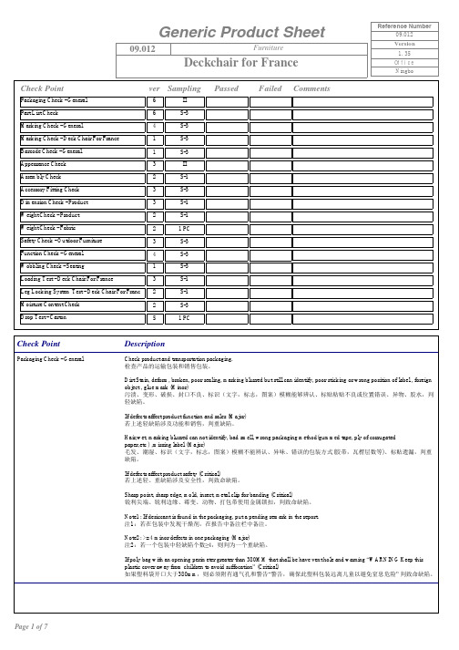
Ningbo Check PointDescription Packaging Check - General Check product and transportation packaging.检查产品的运输包装和销售包装。
Dirt Stain, deform, broken, poor sealing, marking blurred but still can identify, poor sticking or wrong position of label , foreignobject , glue mark (Minor)污渍、变形、破损、封口不良、标识(文字,标志,图案)模糊能够辨认、标贴粘贴不良或位置错误、异物、胶水,判轻缺陷。
If defects affect product function and sales (Major)若上述轻缺陷涉及功能和销售,判重缺陷。
Hair,wet, marking blurred can not identify, bad smell, wrong packaging method(gummed tape, ply of corrugatedpaper,etc ) ,missing label (Major)毛发、潮湿、标识(文字,标志,图案)模糊不能辨认、异味、错误的包装方式胶带,瓦楞层数等、标贴遗漏,判重()缺陷。
If defects affect product safety (Critical)若上述轻、重缺陷涉及安全性,判致命缺陷。
Sharp point, sharp edge, mold, insect, metal clip for banding (Critical)锐利尖端、锐利边缘、霉变、动物、打包带使用金属锁扣,判致命缺陷。
Note1: If desiccant is found in the packaging, put a pending remark in the report.注:若在包装中发现干燥剂,在报告中备注栏中备注。
- 1、下载文档前请自行甄别文档内容的完整性,平台不提供额外的编辑、内容补充、找答案等附加服务。
- 2、"仅部分预览"的文档,不可在线预览部分如存在完整性等问题,可反馈申请退款(可完整预览的文档不适用该条件!)。
- 3、如文档侵犯您的权益,请联系客服反馈,我们会尽快为您处理(人工客服工作时间:9:00-18:30)。
PS163Q Dual Language Kindergarten Class Supply List 皇后區一六三公立小學雙語幼稚班學校用品
= = = = = = = = = = = = = = = = = = = = = = = = = = = = = = = = = = = = = = = = = = = = = = = = = = = = = = = = = = = = = = = = = = = = = = = = = = = = = = = = = = = ∙ 1 school bag – not on wheels and large enough to hold folders and notebooks
一個書包–不要有輪子的, 能放進文件夾和筆記本的大小
∙ 4 Mead hardcover marble notebooks – 9¾ x 7½ inches in size, 100 sheets each, wide rule (200 pages) 四本Mead硬皮封面的筆記本–長寬9¾ x 7½ 吋, 100張, 寬格 (200 頁)
- 2 blue and 2 red 兩個藍色和兩個紅色
∙ 5 Poly (plastic) two-pocket folders with bottom pockets (no trappers) – 2 red, 2 blue, and 1 yellow 五個塑膠文件夾, 下面有兩個口袋–二個紅色和二個藍色和一個黃色
∙1” 3-ring binder
一個一吋的三孔活頁夾
∙ 1 box of Crayola brand 24 pack crayons
一盒 Crayola 牌子的蠟筆 (二十四枝裝)
∙Crayola washable markers
Crayola 牌子的可清洗彩色筆
1.One box of thin markers 一盒細彩色筆
2.One box of thick (broad) markers 一盒粗彩色筆
∙ 2 bottles of Elmer’s 4 ounce white school glue兩瓶Elmer’s 牌子的白膠水, 四盎司
∙ 1 box of standard size #2 pencils – sharpened 一盒標準二號鉛筆–削好
∙ 3 highlighters – yellow or pink or blue 三枝螢光筆–黃色或粉紅色或藍色
∙ 2 pack of Expo dry erase markers (4/pack) 兩盒白板筆 (四枝裝)
∙ 6 pads of post-it notes 3 x 3 inches in size (2 yellow, 2 light pink, and 2 light blue) 六疊 Post-it 便條紙, 長寬 3 x 3 吋 (兩個黃色, 兩個淺粉紅色, 兩個淺藍色)
∙ 1 pair of Fiskar brand scissors (5 inch blunt tip) 一把 Fiskar 牌子的小孩剪刀 (5 吋)
∙ 2 boxes of gallon size bag (Ziploc or Hefty one zip)
二盒可密封或拉鍊的袋子 (容量一加崙, Ziploc 或 Hefty 的牌子)
∙ 1 box of quart size bag (Ziploc or Hefty one zip)
一盒可密封或拉鍊的袋子 (容量一夸脫, Ziploc 或 Hefty 的牌子)
∙ 1 pair of dark colored socks (black, blue, or brown) 一雙深色的襪子 (黑色, 藍色, 或咖啡色)
∙ 2 box of Kleenex facial tissue (200 counts or larger) 兩盒 Kleenex 面紙 (200+ 張)
∙1 roll of paper towels 一捲廚房紙巾
∙ 2 boxes of baby wipes 兩盒嬰兒濕紙巾
∙ 1 tub of Clorox sanitizing wipes 一盒Clorox消毒紙巾
∙ 1 pump style bottle of anti-bacterial soap 一瓶手壓式的殺菌洗手乳
∙ 1 bottle of Purrell instant hand sanitizer (8 oz.) 一瓶 Purrell 含酒精成分的潔手液 (八盎司)
~ ~ ~ ~ ~ ~ ~ ~ ~ ~ ~ ~ ~ ~ ~ ~ ~ ~ ~ ~ ~ ~ ~ ~ ~ ~ ~ ~ ~ ~ ~ ~ ~ ~ ~ ~ ~ ~ ~ ~ ~ ~ ~ ~ ~ ~ ~ ~ ~ ~ ~ ~ ~ ~ ~ ~ ~ ∙For Science and Media Class: 1 GREEN and 1 BLACK two-pocket folder with bottom pockets 給自然課和圖書館課使用: 一個綠色和一個黑色的塑膠文件夾, 下面有兩個口袋。