Skinner(美国产)系列比例调节电磁阀(介质空气
Parker Hannifin 水力卡特车系Check Valve系列产品说明说明书

ISO code 16/13, SAE Class 4 or better
.10 kg (0.2 lbs.)
Technical Data
CV9
Parker Hannifin Corporation Hydraulic Cartridge Systems
Bodies & Cavities
Coils & Electronics
Proportional Valves
Solenoid Valves
Manual Valves
Directional Controls
Logic Elements
Pressure Controls
Flow Controls
Load/Motor Controls
Form Tool
38 LPM (10 GPM)
350 Bar (5000 PSI)
2 drops/min. (.13 cc/min.) at 350 Bar (5000 PSI)
All parts steel. All operating parts hardened steel.
-45°C to +93.3°C (“D” Ring) (-50°F to +200°F) -31.7°C to +121.1°C (Fluorocarbon) (-25°F to +250°F)
Features
• Spherical poppet for low leakage • “D”-Ring eliminates back-up rings • Dual sense paths for reduced ∆P • All external parts zinc plated
Wilkerson Corp 9EM-TK-190-1 1 8 寸空气分区筛选器与压力调节器说明书

128Catalog 9EM-TK-190-1Pneumatic Division Richland, MichiganAcce p Filter / Regulator B03Features• Excellent Water Removal Efficiency • Unbalanced Poppet Standard • Solid Control Piston for Extended Life• Space Saving Package offers both Filter and Regulator features in One Integral Unit • Non-rising Adjustment Knob • Two Full Flow 1/8" Gauge PortsSpecificationsFlow Capacity* 1/8 16 SCFM (7.5 dm 3/s)1/4 18 SCFM (8.5 dm 3/s)Gauge Ports (2) 1/8 Inch Port Threads1/8, 1/4 InchPressure & Temperature Ratings – Plastic Bowl 0 to 150 PSIG (0 to 10.4 bar)32°F to 125°F (0°C to 52°C) Metal Bowl 0 to 250 PSIG (0 to 17.3 bar)32°F to 175°F (0°C to 80°C)Secondary Pressure Ranges –Standard Pressure2 to 125 PSIG (0 to 8.6 bar) Medium Pressure 1 to 60 PSIG (0 to 4.1 bar)Medium Pressure1 to 30 PSIG (0 to 2.1 bar) Low Pressure 1 to 15 PSIG (0 to 1.0 bar)Weight .4 lb. (.18 kg)Bowl Capacity1 Ounce* Inlet pressure 100 PSIG (6.9 bar). Secondary pressure 90 PSIG (6.2 bar). and 10 PSIG pressure drop.Materials of ConstructionAdjusting Nut Brass Adjusting Stem & SpringSteel BodyZinc Bonnet, Knob, Seat, Piston, Holder & DeflectorPlasticBowls – Transparent PolycarbonateMetal (Without Sight Gauge) ZincFilter Elements – 5 Micron (Standard) Plastic Manual Drain – Body & StemPlastic SealsNitrile Piston Drain – Piston & Seals Nitrile Stem, Seat, Adaptor & Washers AluminumSealsNitrileDimensionsWith Piston DrainB03-02-0000WARNINGProduct rupture can cause serious injury.Do not connect regulator to bottled gas.Do not exceed maximum primary pressure rating.!NOTE: 1.218 Dia. (31mm) hole required for panel mounting.(Revised 2-26-07)Catalog 9EM-TK-190-1129Pneumatic Division Richland, MichiganOrdering Information206080401001234562468101214Relief And Flow CharacteristicsS e c o n d a r y P r e s s u r e - P S I GS e c o n d a r y P r e s s u r e - b a rRated Flow - SCFMFlow - dm /s3n20608040100123456 Relief And Flow CharacteristicsS e c o n d a r y P r e s s u r e - P S I GS e c o n d a r y P r e s s u r e - b a rFlow - dm /s3nReplacement KitsPoly Bowl –Piston Drain ...............................................................PS408B Manual Drain ................................................................PS404Metal Bowl –Piston Drain ................................................................PS451B Manual Drain .............................................................PS447B Filter Element Kit, 5 Micron ..............................................PS403AccessoriesGauges –30 PSIG (0 to 2.1 bar) .......................................K4515N18030 60 PSIG (0 to 4.1 bar) .......................................K4515N18060 160 PSIG (0 to 11.0 bar) ...................................K4515N18160Mounting Bracket Kit (Includes Panel Mount Nut) .........PS417B Panel Mount Nut –Plastic ........................................................................P78652 Metal ...........................................................................P01531Poppet Valve Kit ...........................................................PS424B Service Kits –Non-Relieving ...............................................................PS422 Relieving .......................................................................PS423Springs –1 to 15 PSIG Range .....................................................P01176 1 to 30 PSIG Range .....................................................P01175 1 to 60 PSIG Range .....................................................P011742 to 125 PSIG Range ...................................................P01173CAUTION:REGULATOR PRESSURE ADJUSTMENT – The working range of knob adjustment is designed to permit outletpressures within their full range. Pressure adjustment beyond this range is also possible because the knob is not a limiting device. This is a common characteristic of most industrial regulators, and limiting devices may be obtained only by special design.For best performance, regulated pressure should always be set by increasing the pressure up to the desired setting.Filter / Regulator B03。
EX260-PEC1 产品名 一体化泵系统集成阀门 manifold 型号 EX260-PEC1说明

Doc. No.EX##-OMA1006SI Unit for ejector system integrated valve manifoldEX260-PEC1Safety InstructionsThese safety instructions are intended to prevent hazardous situations and/or equipment damage. These instructions indicate the level of potential hazard with the labels of "Caution", "Warning" or "Danger". They are all important notes for safety and must be followed in addition to International Standards (ISO/IEC)*1), and other safety regulations.*1) ISO 4414: Pneumatic fluid power -- General rules relating to systems.ISO 4413: Hydraulic fluid power -- General rules relating to systems.IEC 60204-1: Safety of machinery -- Electrical equipment of machines .(Part 1: General requirements)ISO 10218: Manipulating industrial robots -Safety.etc.Safety InstructionsRead and accept them before using the product.NOTE○Follow the instructions given below when designing, selecting and overseeing the product.•The instructions on design and selection (installation, wiring, environment, adjustment, operation,maintenance, etc.) described below must also be followed.*Product specifications•Use the specified voltage.Otherwise, failure or malfunction can result.•Reserve a space for maintenance.Allow sufficient space for maintenance when designing the system.•Do not remove any nameplates or labels.This can lead to incorrect maintenance, or misreading of the operation manual, which could cause damage or malfunction to the product.It may also result in non-conformity to safety standards.•Pay attention to the inrush current at power-up.Depending on the connected load, the initial charge current may cause the overcurrent protection and malfunction can result.•Product handling*Installation•Do not drop, hit or apply excessive shock to the fieldbus system.Otherwise, damage to the product can result, causing malfunction.•Tighten to the specified tightening torque.If the tightening torque is exceeded the mounting screws may be broken.IP67 protection cannot be guaranteed if the screws are not tightened to the specified torque.• When carrying the manifold, make sure that the connections are not stressed.Otherwise, the damage to connections can result. In addition, some combinations of the manifold may be very heavy, so use more than one person to carry or install the manifold.•Never mount a product in a location that will be used as a foothold.The product may be damaged if excessive force is applied by stepping or climbing onto it.*Wiring•Avoid repeatedly bending or stretching the cables or placing heavy load on them.Repetitive bending stress or tensile stress can cause breakage of the cable.•Wire correctly.Incorrect wiring can break the product.•Do not perform wiring while the power is on.Otherwise, damage to the fieldbus system and/or I/O device can result, causing malfunction.•Do not route wires and cables together with power or high voltage cables.Otherwise, the fieldbus system and/or I/O device can malfunction due to interference of noise and surge voltage from power and high voltage cables to the signal line.Route the wires (piping) of the fieldbus system and/or I/O device separately from power or high voltage cables.•Confirm proper insulation of wiring.Poor insulation (interference from another circuit, poor insulation between terminals, etc.) can lead to excess voltage or current being applied to the product, causing damage.•Take appropriate measures against noise, such as using a noise filter, when the fieldbus system is incorporated into equipment.Otherwise, noise can cause malfunction.*Environment•Select the proper type of protection according to the environment of operation.IP67 protection is achieved when the following conditions are met.However, when connected with JSY1000 manifolds, it is IP40.(1) The SI Unit is connected properly with fieldbus cable with M8 connector and power cable with M8 connector.(2) Suitable mounting of the SI Unit and manifold.(3) Be sure to fit a seal cap on any unused connectors.If using in an environment that is exposed to water splashes, please take measures such as using a cover.•Do not use in a place where the product could be splashed by oil or chemicals.If the product is to be used in an environment containing oils or chemicals such as coolant or cleaning solvent, even for a short time, it may be adversely affected (damage, malfunction etc.).•Do not use the product in an environment where corrosive gases or fluids could be splashed.Otherwise, damage to the product and malfunction can result.•Do not use in an area where surges are generated.If there is equipment that generates a large amount of surge (solenoid type lifter, high frequency induction furnace, motor, etc.) close to the fieldbus system, this may cause deterioration or breakage of the internal circuit of the fieldbus system. Avoid sources of surge generation and crossed lines.•When a surge-generating load such as a relay or solenoid is driven directly, use a fieldbus system with a built-in surge-absorbing element.Direct drive of a load generating surge voltage can damage the fieldbus system.•The product is CE marked, but not immune to lightning strikes. Take measures against lightning strikes in the system.•Prevent foreign matter such as remnant of wires from entering the fieldbus system to avoid failure and malfunction.•Mount the product in a place that is not exposed to vibration or impact.Otherwise, failure or malfunction can result.•Do not use the product in an environment that is exposed to temperature cycle.Heat cycles other than ordinary changes in temperature can adversely affect the inside of the product.•Do not expose the product to direct sunlight.If using in a location directly exposed to sunlight, shade the product from the sunlight.Otherwise, failure or malfunction can result.•Keep within the specified ambient temperature range.Otherwise, malfunction can result.•Do not operate close to a heat source, or in a location exposed to radiant heat.Otherwise, malfunction can result.*Adjustment and Operation•Perform settings suitable for the operating conditions.Incorrect setting can cause operation failure.•Please refer to the PLC manufacturer's manual etc. for details of programming and addresses. For the PLC protocol and programming refer to the relevant manufacturer's documentation.*Maintenance•Turn off the power supply, stop the supplied air, exhaust the residual pressure and verify the release of air before performing maintenance.There is a risk of unexpected malfunction.•Perform regular maintenance and inspections.There is a risk of unexpected malfunction.•After maintenance is complete, perform appropriate functional inspections.Stop operation if the equipment does not function properly.Otherwise, safety is not assured due to an unexpected malfunction or incorrect operation.•Do not use solvents such as benzene, thinner etc. to clean each unit.They could damage the surface of the body and erase the markings on the body.Use a soft cloth to remove stains.For heavy stains, use a cloth soaked with diluted neutral detergent and fully squeezed, then wipe up the stains again with a dry cloth.Fieldbus System/Industrial IoT Cybersecurity In recent years, factories have introduced industrial IoT, building up complex networks of production machines. These systems maybe subject to a new threat, cyberattack. To protect the industrial IoT from cyberattacks, it is important to take multiple measures (multi-layer protection) for IoT devices, networks and clouds.For this purpose, SMC recommends that the following measures are always taken into consideration. For further details of the following measures, please see security information published by your local country security agencies.1. Do not connect the devices via a public network.• If you unavoidably need to access the device orcloud via a public network, ensure to use a secure,private network such as VPN.• Do not connect an office IT network and factory IoT network.2. Build a firewall to prevent a threat from entering the device and system.• Set up a ro uter or firewall at network boundaries toallow minimum required communications.• Disconnect from the network or turn off the device if no continuous connection is required.3. Physically block an access to unused communication ports or disable them.• I nspect regularly each port if any unnecessarydevice is connected to the network system.• Operate necessary services (SSH, FTP, SFTP, etc.) only.• Set a transmission range of the device using awireless LAN or other radio system to the minimumrequired and use only devices approved according to the radio act in the country concerned.• Install a device generating radio waves in such place as there is no interference from indoor or outdoor. 4. Set up a secure communication method such as data encryption.• Encrypt data in every environment, including IoTnetworks, secure gate-way connections, for securecommunications.5. Grant access permissions by user accounts and limit the number of users.• Regularly review accounts and delete all unusedaccounts or permissions.• Establish an account lockout system to block anaccess to the account for a certain period if log-infails more than the given threshold.6. Protect passwords.• Change the default password when you firstuse the device or system.• Choose a long password (minimum 8characters) using a mix of different letters and characters to make the password more secure and harder to hack.7. Use the latest security software.• Install antivirus software on all computers todetect and remove viruses.• Keep the antivirus software up to date.8. Use the latest version of the device and system software.• Apply patches to keep the OS and applications up to date.9. Monitor and detect abnormalities in the network.• Keep monitoring t he network for anyabnormalities to take a prompt measure andissue an alert if any abnormality is detected.Install an intrusion detection system (IDS) and intrusion prevention system (IPS).10. Delete data from devices when disposed of. • Before disposi ng of any IoT devices, deletestored data or physically destruct media toprevent any misuse of the data.1.This document is an operation manual for a SI (Serial Interface) Unit which controls ejector system integrated valve manifold (JSY series). The SI Unit is a EtherCAT®-compatible device. EtherCAT® is registered trademark and patented technology, licensed by Beckhoff Automation GmbH, Germany. The SI Unit controls the manifold which has 5 pressure sensors max., and 24 valves output max.. For valve manifold, refer to the instruction manual for ejector system integrated valve manifold.Fig 1-1. The SI Unit structure2.Select the appropriate cables to mate with the connectors mounted on the SI Unit.2.1. Communication connectorECAT IN/OUT: M8 4 pin socket A-codedFig 2-1. Pin allocation of communication connectorWarningPay attention not to confuse the communication connector with the power connector. Incorrect connection may result in SI Unit failure. Check the printed character.2.2. Power connectorPWR IN: M8 4 pin plug A-codedPWR OUT: M8 4 pin socket A-codedFig 2-2. Pin allocation of power connectorPower-supply line for logic/sensors and power-supply line for valves are isolated. Be sure to supply power respectively.It can be used either with two different power supply or single-source power supply.NOTEThe recommended tightening torque is 0.2 Nm for both communication connectors and powerconnectors.2.3. FE terminalThe SI Unit must be connected to FE (Functional Earth) to divert electromagnetic interference. Connect a grounding cable from the FE terminal screw on the SI Unit to the nearest functional earth point. The grounding cable should be as thick and short as reasonably possible.The FE terminal and the metal parts of the communication/power connector are internally connected. The recommended tightening torque for FE terminal is 0.3 Nm.Fig 2-3. FE terminal3.1. ESI fileTo configure the SI Unit with your EtherCAT® master's software, the dedicated ESI (EtherCAT Slave Information) file is required. The ESI file contains all necessary information to configure the SI Unit on your master's software.The ESI file name is as follows. The ESI file can be downloaded from the SMC website.•ESI file: SMC_EX260-PECx_V10.xml3.2. Energy saving parameterNOTE•For energy saving function of ejector, see e.g. the catalogue for ejector system integrated valve manifold.The energy saving function is supported by ejector that can hold vacuum pressure.Check in advance whether your ejector is compatible with the energy saving function.•If there is an overlap OUT No. or order error in the set values, the Diagnosis history "Warning"occurs and SF LED flashes green and stops energy saving operation for sensor No. with error.•Incorrect OUT No. setting may result in unintended valve output.4.1. Input process data4.1.1. Pressure value of sensor No.x (of each 5 sensors)NOTE•Fixed at 0 for unconnected sensor.•Hold last data during happened sensor wire break and error etc..4.1.2. Valve-coil(s) short circuit diagnosis4.1.3. Unit diagnosis4.1.4. Sensor state of sensor No.x (of each 5 sensors)NOTEFor judgement of vacuum/pressure generation, refer to Section 5.1.1 and Section 6.4.2. Output process data4.2.1. Output5.NOTE*1) RO means Read only, WO means Write only, and RW means both Read and Write are allowed. Those with a trailing P are the Index assigned to the process data, and the format is the same.5.1. Sensor parameters(Index 0x8009/8019/8029/8039/8049)5.1.1. Pressure parameter (Subindex 0x01...0x08)NOTE•If the pressure parameter set values do not fulfil the conditions in (1)...(4) above, the Diagnosis history "Warning" occurs and SF LED flashes green and applicablevacuum/pressure state bit (Offset 0.0...0.3 in Section 4.1.4) is fixed at 0 for the applicable sensor.•If the pressure parameter set values do not fulfil the conditions in (2) above and the energy saving parameter is set to other than Disable, stop energy saving operation for the applicable sensor.5.1.2. Supply valve type (Subindex 0x09)NOTE•The setting must match supply valve type of actual ejector. If the settings are different from the actual specifications, energy saving operation is not possible.5.1.3. Valve protection (Subindex 0x0A)5.2. Output parameters5.2.1. Output counter (Index 0xF120)5.2.2. Output operation at network fault (Index 0xF800)5.2.3. Output counter limit monitoring(Index 0xF801)5.2.4. Output counter limit value (Index 0xF802)5.3. General parameters5.3.1. Number of sensors (Index 0xF803)NOTE•If the number of sensors detected by the SI Unit is greater than the set number, the unit will operate normally without occurring an error.5.4. Command parameters5.4.1. Zero offset (Index 0xB008/B018/B028/B038/B048/FB00)NOTE•Zero offset should be performed with sensor open to the atmosphere.Zero offset is performed only when the pressure value is within ±2 % F.S. of atmospheric pressure.•"Zero offset reset request" clears the zero offset correction.•"Zero offset of all sensors" is used to zero offset all sensors at once.5.4.2. Valve protection release (Index 0xFB01)NOTE•Valve protection release is performed for all ejectors at once.•If the valve protection occurs, the diagnostic bit will be deleted, and the SF LED will be turned off by the above requests.5.4.3. Output count reset (Index 0xFB02)NOTE•The Output count reset can be reset for each output individually and is entered according toa 4 byte (32 bit) number.Example: Set 0x00001234 -> Output count reset request of OUT2,4,5,9,12Example: Set 0x1234ABCD -> Output count reset request of OUT0,2,3,6,7,8,9,11,13,15,18,21•If output count over occurs, the diagnostic bit will be deleted, and the SF LED will be turned off by the above requests.6.Fig 6-1. Example of energy saving operation (Conditions under which release pressure is generated) • (1)When the vacuum instruction is ON, the supply valve is automatically closed when the vacuum pressure reaches P2.• (2)When the vacuum pressure drops by P2-H2, the supply valve is automatically opened again. • (3)Repeat steps (1) and (2) unless the valve protection is activated.• (4)The vacuum P1 state bit is set to 1 until the vacuum pressure reaches P1 and then drops to P1-H1. • (5)The vacuum P2 state bit is set to 1 until the release pressure reaches P2 and then drops to P2-H2. • (6)The pressure P3 state bit is set to 1 until the vacuum pressure reaches P3 and then drops to P3-H3. • (7)The pressure P4 state bit is set to 1 until the vacuum pressure reaches P4 and then drops to P4-H4. • The above pressure threshold/hysteresis combinations are set by CoE services, Refer to Section 5.1.1.Vacuum instruction (OUTx ON/OFF)Supply valve Release instruction (OUTy ON/OFF)Vacuum P2state bit Release Valve Vacuum P1state bit Pressure P3state bit Pressure P4state bitEnergy saving parameter set to OUTx-y, Supply valve type : N.C.Threshold of Vacuum P1Energy savingoperationThreshold of Pressure P3Threshold of Pressure P47.7.1. LED IndicationFig 7-1. LED Indicators of the SI UnitRUN ERR SF L/A1L/A2PWR PWR(V)Fig 7-2. LED lighting patterns 7.2. Diagnosis history8.8.1. DimensionsFig 8-1. Dimensions of the SI Unit8.2. SpecificationsNOTE*1: SI Unit power supply voltage specification. Supply power according to the solenoid valve used.9.(1) Seal capPart number: EX9-AWESThis cap is used to protect the M8 socket connector opening when the connector is not used.When a connector is not used, the seal cap can keep the SI Unit under IP67 rated protection.(2 pcs. are included with the SI Unit as an accessory.)Fig 9-1. EX9-AWES10.The state of the SI Unit is indicated by the LED indication.If a problem occurs on the SI Unit, you can use the following chart to troubleshoot.Also refer to the online diagnostics via the EtherCAT® master software to help identify the problem.10.1. Troubleshooting chartFig 10-1. Troubleshooting chart10.2. Troubleshooting tablesNOTE•The Diagnosis history (Section 7.2) allows identification of the OUT No. or sensor No. that is causing the problem.4-14-1, Sotokanda, Chiyoda-ku, Tokyo 101-0021 JAPANTel: + 81 3 5207 8249 Fax: +81 3 5298 5362URL https://Note: Specifications are subject to change without prior notice and any obligation on the part of the manufacturer.© 2022 SMC Corporation All Rights ReservedNo.EX##-OMA1006。
尼尔森电磁阀 说明书

尼尔森电磁阀
使用说明书
9502系列活接阀
9515、9520系列(既可做直通阀,又可做角阀)
9000系列7900系列
一.介绍
感谢您选用尼尔森电磁阀。
请仔细阅读以下说明,以便了解其安装和保护的重要措施。
二.安装说明
1.尼尔森电磁阀的过水方向均在阀上用箭头标明,安装时注意进、出水方向。
2.管道连接时注意不要让难排出的杂物进入(尤其是小石块,很容易在以后的运行中卡在电磁阀隔膜下方,造成电磁阀无法自动关闭)
3.电磁阀安装之前应配备检修阀,以方便今后的维修。
三.维修
在使用过程中,如发现电磁阀出现问题(如不能启动或正常关闭),请先检查水源、控制器的连接与设置等,在确定其它部件正常的情况下,参照以下方法检查电磁阀:
1.电磁阀无法正常启动
可能的故障原因解决办法
1电磁先导阀损坏更换电磁先导阀
清洗柱塞
2电磁先导阀内柱塞不能灵
敏回缩
3电磁先导阀接头处电压低检查电线和控制器
4电磁先导阀下的进排水孔
用细钢丝或曲别针疏通被堵塞
5流量调节手柄关闭逆时针方向旋转手柄
2.电磁阀无法正常关闭
可能的故障原因解决办法
1电磁先导阀被拧松(手动排放打开)拧紧电磁先导阀(关闭手动排放)
2电磁先导阀内柱塞不能灵
敏回缩
清洗柱塞
3隔膜被卡住而无法下落拆开阀盖,取出异物
4电磁阀阀体密封不严重新安装,拧紧螺丝
5隔膜被破坏更换隔膜
6流量调节手柄开到最大顺时针方向旋转手柄(3/4
圈)
内部构造简图
检修阀
9501活接阀。
氢气集装格阀门规格
氢气集装格阀门规格
- 美国rego高压总阀HP9560:这是一款低温气体充装阀,适用于氢气、氧气、氮气等气体的集装格。
其连接形式为螺纹,材质为黄铜,公称通径为DN15,压力环境为高压,标准为美标,外形为微型,流动方向为单向,驱动方式为气动。
- 衬胶隔膜阀SEG41W-16P:此型号的阀门使用介质为氢气,阀门材质要求304不锈钢,阀门内部有阀座、阀芯杆组件、四氟隔膜垫片(PTEF+EPDM)组成,所有内部件均可以拆卸方便与更换,零泄漏标准。
其尺寸要求为:阀门长度127mm,法兰孔距85mm。
- 衬胶隔膜阀G41J-10/DN25:该型号的阀门使用介质同样为氢气,其阀门长度为145mm,法兰孔距为85mm。
- 衬胶隔膜阀G41J-10/DN50:这款型号的阀门使用介质也是氢气,其阀门长度为210mm,法兰孔距为125mm。
需要注意的是,以上规格仅供参考,实际应用中可能会有所不同。
在选择氢气集装格阀门时,建议咨询专业人士或参考相关标准和规范,以确保选择合适的阀门规格。
伦纳德阀门TM-26恒温水混合阀安装使用说明书
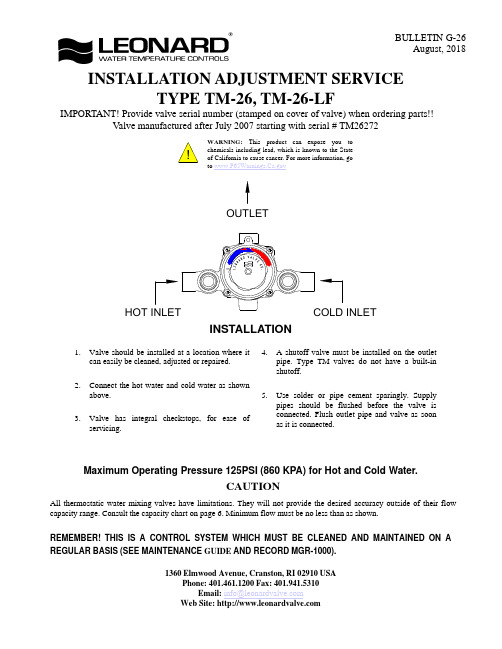
INSTALLATION ADJUSTMENT SERVICEADJUSTMENT AND SERVICEWARNINGThis mixing valve is equipped with an adjustable high temperature limit stop factory set at approximately 120°F (49°C)with an incoming hot water supply temperature of 150°F (65.5°C).If the hot water supply temperature of the job is greater than 150°F (65.5°C),the valves when turned to full HOT will deliver water in excess of 120°F (49°C)and the limit stops MUST BE RESET BY THE INSTALLER!TO RESET ADJUSTABLE HIGH TEMPERATURE LIMIT STOP:1.Loosen LTR Set Screw,remove POINTER SCREW.2.Adjust POINTER to maximum desired temperature.3.Remove POINTER,replace POINTER on spline rod withSTOP (which is cast into the underside on the pointer),resting against the BOTTOM side of the WEB on the FINE ADJUSTMENT SCREW.4.If fine adjustment is needed,adjust FINE ADJUSTMENTSCREW on the cover,loosen for hotter or tighten for cooler temperature.5.Replace POINTER and check temperature,if set to desiredtemperature replace POINTER SCREW,and tighten LTR SET SCREW.6.The new maximum temperature has now been set.Test thistemperature by holding a thermometer under the flow of water to be certain it is as desired.*LIMIT STOP MUST BE RESET AND RECHECKED EACH TIME HANDLE IS REMOVED.WARNINGWARNING!This Thermostatic Mixing Valve has an adjustable high temperature limit stop which,must be checked.If temperature is too high,the installer MUST RESET this stop immediately.Always check the temperature of the mixed water when the lever handle is turned to full HOT.Excessively hot water is DANGEROUS AND MAY CAUSE SCALDING!The high temperature limit stop is factory set at approximately 120°F (49°C)with an incoming hot water supply temperature of 150°F (65°C).If the incoming hot water on the job is higher than 150°F (65°C),the valve when turned to full hot will deliver water in excess of 120°F (49°C)and the high temperature limit stop MUST BE RESET BY THE INSTALLER.Check for significant variations in outlet flow.Thermostatic valves will NOT provide the desired accuracy outside of their flow capacity range.Minimum flows must be no less than shown (see Flow Capacities,page 6).If installed on a recirculated hot water system,make certain the valve is piped according to Leonard Required Piping Method #2(see page 4).REMEMBER!THIS IS A CONTROL DEVICE WHICH MUST BE CLEANED AND MAINTAINED ON A REGULAR BASIS.(SEE MAINTENANCE GUIDE AND RECORD,MGR-1000).WEBADJUSTMENT FINESCREW1017ASSE COLDHOT(REST STOP AGAINST SCREW)SET SCREWLTRSTOPPOINTER POINTER SCREWLeonard Type TM Thermostatic Water Mixing Valves are simple in design and may be easily cleaned,adjusted and repaired. If the installation is accessible, servicing may be completed without disconnecting the valve.NOTE:Thermostatic Water Mixing Valves are REGULATING mechanisms,which must be regularly maintained to provide best performance.Frequency of cleaning depends on quality of local water conditions and usage.(See Maintenance Guide and Record MGR-1000).REQUIRED METHODS OF PIPING TM V ALVES (RECIRCULATED HOT WATER SYSTEMS)METHOD #1METHOD #1Required when hot water supply is to be circulated to a master mixer or individual thermostatic mixing valves which are a substantial distance from the hot water source.It is used primarily in a building with several risers,with tempered water in each riser controlled by a separate master mixer.NOTE:The engineer must determine maximum distance which can be run,i.e.maximum allowable time for hot water to reach user with one shower head operating,based upon code requirements and/or good practice.METHOD #2METHOD #2setup INSTRUCTIONSBefore any attempt is made to adjust this system,be sure the temperature of the hot water at the source is properly set and maintained.1.Be sure system is piped in accordance with Method #2.2.Shut off circulator.3.Open enough fixtures to flow 2TO 4GPM.4.Set mixing valve to the desired temperature,(note Warning Tag attached to the pointer of the valve).5.Shut off all fixtures.Note:At this point,be sure NO water is being drawn through any fixture until the temperature in the recirculated line has been set.6.Open the balancing valve approximately 1/2way and start the circulator.Make sure no water is being drawn.7.Observe the temperature until it stabilizes.8.Close the ball valve slightly if the temperature is too hot,or open if it is too cold and again let the temperature stabilize.Repeat until the desired recirculated temperature is set.CIRCULATE HOT WATER FROM END OF LINE BACK TO TANK (THIS PIPING IS NOT TO BE USED FOR AN ENTIRE BUILDING!)HOT SUPPLY COLD SUPPLYBALL VALVETO FIXTURESTEMPERED WATER CTCHECK VALVEBALANCING VALVECIRCULATORAQUASTATTEMPERED FIXTURESTEMPERED RETURNHIGH TEMPERATURE RETURNCOLD SUPPLYHEAT TRAPCCIRCULATORTEMPERED BALL VALVE FOR SETUP (OPTIONAL)HIGH TEMPERATURE FIXTURES (IF APPLICABLE)CHECK VALVEISOLATION VALVEHOT WATER SOURCE(SEE NOTE BELOW)NOTE:FOR MULTIPLE TEMPERED LOOPS, A BALANCING VALVE AND CHECKVALVE MUST BE INSTALLED ON EACH LOOP AFTER TEMPERED FIXTURESTROUBLESHOOTING INSTRUCTIONSSee page 5 for Parts BreakdownsPACKINGS & GASKETS1.Leak at pointer rod.2.Leak between valve cover and base.PARTS REQUIRED:KIT#1/26(PACKINGS & GASKETS)PORT SLEEVE ASSEMBLY3.Valve delivers either all hot or all cold water, or will not mix consistently.KIT#R/28(REBUILDING KIT)OR TM-28-1-8B BRIDGE ASSEMBLY THERMOSTAT GROUP 4.After cleaning or replacing port sleeve assembly, valve will not hold temperature.KIT#R/28(REBUILDING KIT)OR TM28-G2THERMOSTAT GROUP CHECKSTOPS5.Hot water bypass into cold line.6.Supplies cannot be shut off completely.7.Leak at checkstop bonnet.KIT#4/M20(CHECKSTOP KIT)INSTRUCTIONS FOR DISMANTLING VALVE (DWG.1)1.Shut off hot and cold supplies to valve.2.Remove four Cover Screws M20-2C to release entire thermostatic control assembly.WHEN RE-ASSEMBLING VALVE ,insert Cover Gasket M20-3C in base.Lubricate TM28-6B O'Rings before re-inserting assembly.After installing new parts,it will may be necessary to reset high temperature limit.See instructions "TO RESET ADJUSTABLE HIGH TEMPERATURE LIMIT STOP"(page 2).TO REMOVE BRIDGE ASSEMBLY (DWG.2)Remove MU-10B Pointer Rod Nut,remove TM28-1-8B Bridge Assembly from pointer rod.Failure to properly blend the water may be caused by a sticking condition in the TGM-1/28Port Sleeve Assembly.The Thimble should slide freely on the Port Sleeve.Clean with a NON-CORROSIVE CLEANING AGENT AND SOFT CLOTH.DO NOT USE ABRASIVES,then wash parts thoroughly.To reassemble,replace Bridge Assembly on pointer rod.Driving ball on Thimble MUST engage hole in coil bracket.Replace pointer rod nut.DO NOT apply grease or lubricants to the TGM-1/28Port Sleeve Assembly.TO DISASSEMBLE BRIDGE ASSEMBLY (DWG.3)Remove TM25-3A Holder Nuts using a screwdriver in the slots provided.Clean or replace TGM-1/28Port Sleeve Assembly following instructions above.When reassembling,check TM-25-3B port sleeve packings and replace if necessary.TO CLEAN OR REPLACE THERMOSTAT GROUP Loosen gland nut.Push rod through cover.BE CAREFUL NOT TO PULL THERMOSTAT COIL OUT OF SHAPE.To clean,if a deposit has collected on the thermostat group,brush in a non-corrosive cleaning solution.Rinse in clean water and replace in cover with parts as shown.TM-26 V ALVE PARTSREMEMBER!THIS IS A CONTROL DEVICE WHICH MUST BE CLEANED AND MAINTAINED ON A REGULAR BASIS (SEE MAINTENANCE GUIDE AND RECORD).NOTE:AFTER INSTALLING NEW PARTS IT WILL BE NECESSARY TO RESET THE ADJUSTABLE HIGH TEMPERATURE LIMIT STOP ON EACH V ALVE (SEE PAGE 2).CHECKSTOP PARTSREPAIR KITSMU-5A UPPER CHECKSTOPSSTEM O'RINGM20-3A BONNETPACKINGAND PACKINGUPPER STEM CHECK SPRINGM20-6A LOWER STEM & PACKINGM20-9ACHECK BONNETM20-2A RF/CP MU-4A RF/CP (2 REQ'D)TGM-1/28BRIDGE(2 REQ'D)HOLDER NUT O'RINGTM28-6BTM25-5P.S. PACKING (2 REQ'D)PORT SLEEVE TM25-3B ASSEMBLYPOINTER ROD NUTM20-1C RF/CPP.S. HOLDER NUTMU-4CTM25-3ADIAL PLATE57-D COVERTM28-G2THERMOSTAT GROUP(2 REQ'D)TM25-3P.S. HOLDER MU-10BM20-3C GASKETCOVER 3307POINTER7628LTR SET SCREW6910POINTER SCREW7520RF/CP-CHOOSE ONE RF ROUGH FINISH CP CHROME FINISHM20-2CCOVER SCREWSGLAND NUTGLAND PACKING(2 REQ'D)TM28-1-8BBRIDGE ASSEMBLY& PKG. (2 EACH)KIT R/28 REBUILDING KITKIT 4/M20 CHECKSTOP KITCONTROL ASSEMBLYKIT 1/26 PACKINGS & GASKETSLOWER STEM O'RING (2 EACH)HOLDER NUT LOWER STEM & PACKINGBONNET PKG.2 EACH:M20-6A M20-3C GASKETCOVER (2 EACH)GLAND PKG.M20-3A(2 EACH)MU-4C STEM O'RINGMU-5A UPPER GASKETM20-3C COVER M20-3A BONNET PKG.TM28-1-12B THERMOSTATIC (2 EACH)O'RING MU-5A M20-6A TM28-6B CHECK SPRINGCHECK SPRINGM20-9AM20-9A(2 EACH)TEMPERED WATERTO BUILDINGBALL VALVE FULL LINE SIZE SYSTEMOUTLET OF HIGH-LOW PIPE TO OUTLET OF HIGH LOW SYSTEM(A)BALL VALVEOPTIONAL OUTLET SETUP PIPING(BY OTHERS)The addition of this piping arrangement (extra tee and ball valve)eliminates the need to turn showers on and off throughout the building at setup.The flows required in the setup instructions (page 3)are set by using Ball Valve A.(make sure main outlet ball valve is closed).CAUTION!ALL THERMOSTATIC WATER MIXING VALVES AND SYSTEMS HAVE LIMITATIONS!THEY WILL NOT PROVIDE THE DESIRED PERFORMANCE OUTSIDE OF THEIR FLOW CAPACITY RANGE!CONSULT THE CAPACITY CHART BELOW AND OBSERVE MINIMUM FLOWS SHOWN.FLOW CAPACITIES1360 Elmwood Avenue, Cranston, RI 02910 USAPhone: 401.461.1200 Fax: 401.941.5310LIMITED WARRANTYLeonard Valve Company (hereinafter,“Leonard”)warrants the original purchaser that products manufactured by Leonard will befree from defects in material or workmanship under normal conditions of use,when properly installed and maintained in accordance with Leonard’s instructions,for a period of one year from the date of shipment.During this period,Leonard will at its option repair or replace any product,or part thereof,which shall be returned,freight prepaid,to the Leonard factory and determined by Leonard to be defective in materials or workmanship.Leonard provides no warranty,express or implied,which extends beyond the description contained herein.LEONARD SPECIFICALLY DISCLAIMS ANY AND ALL IMPLIED WARRANTIES OF MERCHANTABILITY OR OF FITNESS FOR A PARTICULAR PURPOSE.Nonetheless,some jurisdictions may not allow the disclaimer of certain implied warranties,in which case Leonard hereby limits such implied warranties to the duration of the limited warranty period contained herein.Some jurisdictions may not allow limitations on how long an implied warranty lasts,so the foregoing durational limitation may not apply to you.In no event will Leonard be liable for labor or incidental or consequential damages.Any alteration or improper installation or use of this product will void this limited warranty.If any provision of this limited warranty is prohibited by law in the applicable jurisdiction,such provision shall be null and void,but the remainder of this limited warranty shall continue in full force and effect.TM-26MODELSYSTEM PRESSURE DROP 72192.130L\MINMAXIMUM FLOW CAPACITYFLOW MINIMUM (GPM)INOUT3/4"3/4"3.71.010*********131.026387.310.75764151.4171.7L\MINGPM BAR PSI 453540508087212.4232.89598253.1263.4。
ASCO电磁阀产品说明

"ia" "i"
"ib"
指火花或温度都不能点燃爆炸性环境的电路, 这些火花 或温度是标准规则指定的保养条件下产生的 (正常和非 正常运行条件下).
指元件装在一种特殊包装内的电气设备,火花或加热元
"m"
件都不能点燃爆炸性环境。
"o"
指浸在油里的电气设备.
"p"
通过中性惰性气体来增压的环境.
"q"
指粉末填充的包装.
Zone 20
Zone 22 : Accidentally present (shorttime-service- never in regular service) < 10 hours/year
电气防爆基础
温度等级
I组
温度 < 150°C or < 450°C 根据设备上积聚的煤矿粉尘
II 组
425°C 429°C - 440°C
305°C 102°C 560°C
防护类型
防护
区域
代号 0 20 1 21 2
22
"d"
描述
指爆炸性元件封装在防爆包装内的电气设备. 这种包装 抵得住爆炸性混合物爆炸时的内部压力,而且能防止爆 炸渗透周围的爆炸性环境.
标志性 图案
"e"
指安全系数高的电气设备. 这种设备免于极端的高温, 在 正常运行条件下不会产生内部和外部电弧、火花.
n-butane n-butyl alcool cyclo hexanon 1,2-dichloro-
ethan acetic acid anhydride
芝加哥芯片实验室Maximatic 4方阀门说明书

MME-44ZEE-D110
Maximatic® 4-way solenoid controlled pilot operated valves are either single solenoid spring return or double solenoid spool valves in #10-32 thread to 1/2” NPT port sizes.
MME-43 2.71 (68.8) 0.17 (4.3) 0.17 (4.3) 1.58 (40.1) 0.26 (6.6) 5.19 (131.8) 7.24 (183.9) 1.77 (45.0) 0.96 (24.4) 0.95 (24.1) 1.97 (50.0) 1.06 (26.1) 0.16 (4.1) 0.80 (20.3) 1.54 (39.1)
MME-42 2.65 (67.3) 0.17 (4.3) 0.13 (3.3) 1.38 (35.1) 0.28 (7.1) 4.49 (114.0) 6.49 (164.8) 1.42 (36.1) 0.74 (13.9) 0.98 (24.9) 1.40 (35.6) 0.86 (21.8) 0.13 (3.3) 0.65 (16.5) 1.51 (38.4)
MME-43WES- EA P EB
MME-44ZES-
Double Solenoid Valves
MME-41NEE-
MME-41PEE-
AB
MME-42QEE-
MME-43WEE-
EA P EB
MME-44ZEE-
- 1、下载文档前请自行甄别文档内容的完整性,平台不提供额外的编辑、内容补充、找答案等附加服务。
- 2、"仅部分预览"的文档,不可在线预览部分如存在完整性等问题,可反馈申请退款(可完整预览的文档不适用该条件!)。
- 3、如文档侵犯您的权益,请联系客服反馈,我们会尽快为您处理(人工客服工作时间:9:00-18:30)。
◆ S kinner kinner((美国产美国产))系列比例调节电磁阀系列比例调节电磁阀((介质介质::空气空气、、中型气体中型气体))BP 系列对于复杂问题提供简单而有可靠的解决方案对于复杂问题提供简单而有可靠的解决方案,,不像普通嗲你擦只能进行简单的开关控制的开关控制,,BP 阀科一从0到最大值之间比例的控制KV 值。
电磁执行部分根据输入信号进行定位根据输入信号进行定位,,位置的变换汇控制流过的流量位置的变换汇控制流过的流量。
应用应用::质量流量控制器制器--医疗器械医疗器械,,尤其是氧气呼吸机尤其是氧气呼吸机。
分析仪表及仪器仪表分析仪表及仪器仪表,,实验仪器核试验室内室内。
功能功能::固态电子优化功能固态电子优化功能。
无摩擦运动保证几百万次无故障无摩擦运动保证几百万次无故障,,无噪音工作无噪音工作。
不锈钢结构钢结构,,幅橡胶动态蜜蜂幅橡胶动态蜜蜂,,丁晴橡胶静态密封丁晴橡胶静态密封。
体积紧凑体积紧凑,,满足大多的应用满足大多的应用。
尤其适合与开环或闭环系统。
Parker Skinner 电磁阀系列电磁阀系列1/8” A126LB13001 A12LB13002 71211SN1MM0071221SN1MM00A116LB13001 A11LB130021/8” 71235SN1AN00 71235SN1EN0071235SN1GN0071235SN1KN0071235SN1MN001/4” 71235SN2AN00 71235SN2EN0071235SN2GN0071235SN2KN0071235SN2MN00Flange 7121FBF4GF00 7121FBF4NF001/8” 71216SN1FU00 71216SN1BL00 71216SN1GL00 7121KBN1GF00 71215SN1EF00 3121BBN1AN00 3121BSN1AN00 71215SN1GF00 7121KBN1LR00 71216SN1JT00 3121BBN1EN003121BSN1EN00 3121BSA6EN00 71215SN1EN00 B2*1400 7121KBN1NF00 71215SN1GN00 3121BBN1GN003121BSN1GN00 3121BSA6GN0071215SN1KN00C2*1277 71215SN1KF00 B2*1250 C2*1251 71215SN1MF0071215SN1MN00 3121BBN1JN00 3121BSN1JN00 B2*1175 3121BBN1LN00 3121BSN1LN00 3121BSA6LN00 C2*1132 C2D420CF71215SN1QN003121BBN1NN003121BSN1NN001/8” C2*1092 C2*1081 Male 71215SN1SN00 C2*1062 Male 71214LE1MN00 B2*1052C2*10513121BBN1QN003121BSN1QN003121BSA6QN0071215SN1VN00Male 71214LE1QN00B2*1026C2*1031Male 71214LE1SN001/4”71216SN2FU00 71216SN2GL00 7121KBN2GR00 7121KBN2GF00 71215SN2EF007121KBN2JR0071215SN2GF007321HBN2SN007121KBN2LR00 71216SN2JT00 71215SN2EN00 7121KBN2NF00 7121KBN2NR00 71215SN2GN00 73212BN2MN00 73212SN2MN00 7321KBY61640 71215SN2KN00 71215SN2KF00 71215SN2MF00 71215SN2MN00 7321KBN2RN00 7121KBN2NV00 7121KBN2QV00 71215SN2QN00 7121KBN2SV00 71215SN2SN00 71214VN2KN00 71214VN2KT00 71214TN2KT00 71214VN2MN00 71214VN2MT00 71214TN2MT00 71215SN2VN00 71214VN2QN00 71214VN2QT00 71214TN2QT00 71214VN2SN00 71214VN2ST00 71215SN21N00 71214TN2ST00 71216SN2BL00 73216BN2MT00 73216SN2MT00 3/8”7221GBN3VN00 73218BN3TN00 7321KBN3SN00 7321KBN3SNW0 72218BN3TN00 72218RN3TV00 Barb71214LT3KN007121KBN3UV00Barb 71214LT3MN00Barb71214LT3QN00Barb71214LT3SN0071215SN33N0071215SN33NHP 7321HBN3TN00 73212BN3SN00 7321KBY63200 1/2” 7321HBN4UN00 73212BN4TN00 7321KBY6320A 7221GBN4VN00 73218BN4UN00 7321KBN4SN00 7321KBN4SNW0 72218BN4UN00 72218RN4UV00 7121KBN44V00 A2LB4017 A26LB40063/4” 73212BN52N00 7321GBN53N00 7321GBN53NMC 7221GBN51N00 7221GBN51NC0 73218BN5VN00 72218BN5VN00 72218RN5VV00 XLG2O760 XLG2O6001” XLG2O1060 73212BN63N00 7321GBN64N00 7321GBN64NMC 7221GBN61N00 7221GBN61NC0 7221GBN64N00 7221GBN64NC0 73218BN64N00 LB27BB6127 LB27B110 XLG2O103011/4” 7321GBN76N00 7321GBN76NMC 73218BN75N00 LB27BB7127 LB27B1201 1/2” 73218BN87N00 7321GBN88N00 7321GBN88NMC LB27BB8127 LB27B130 XLG2O15302” 7321GBN99N00 7321GBN99NMC1/8” 71225SN1EF00 7122KBN1GF00 7122KBN1PR00 71225SN1GF00 71295SN1ENJ1 B11*1400 71295SN1GNJ1 3129BBN1AN00 3129BSN1AN00 71295SN1KNJ1 B11*1200 3129BBN1EN00 3129BSN1EN00 7122KBN1LF00 71225SN1KF003129BBN1GN00 3129BSN1GN00 3129BBN1JN00 3129BSN1JN00 B11*1040 3129BSN1LN00 3129BBN1LN001/4” 71225SN2EF00 7322HBN2SV00 7122KBN2GF00 71225SN2GF00 71295SN2ENJ1 73222BN2MN00 71295SN2GNJ1 71225SN2KF00 7122KBN2LF00 73222SN2MN00 71295SN2KNJ1 3/8” 7322HBN3TN00 73222BN3SN00 73228BN3TN00 72228RN3TV00 72228BN3TV001/2” 7322HBN4UN00 73228BN4UN00 73222BN4TN00 72228RN4UV00 72228BN4UV003/4” 7322GBN53N00 7322GBN53NC0 73222BN52N00 73228BN5VN00 72228BN5VV00 72228RN5VV001”7322GBN64N00 7322GBN64NC0 73222BN63N00 73228BN64N001 1/4” 7322GBN76N00 7322GBN76NC0 73228BN75N001 1/2” 7322GBN88N00 7322GBN88NC0 73228BN87N002” 7322GBN99N00 7322GBN99NC01/4”7321KBN2RE00 7121KBN2SE00 7321KBN2RES0 7121KBN2SES0 3/8” 73218BN3TE00 7321KBN3SE00 7221GBN3VE00 73218BN3TTS0 72218BN3TE00 72218RN3TE00 72218RN3TES0 7321KBN3SES0 73218BN3TES0 7221GBN3VES0 72218BN3TES0 1/2” 73218BN4UE00 7321KBN4SE00 7221GBN4VE00 73218BN4UTS0 72218BN4UE00 72218RN4UE00 7221GBN4VES0 72218BN4UES0 7321KBN4SES0 73218BN4UES0 72218RN4UES0 3/4” 73218BN5VE00 7221GBN51E00 73218BN5VTS0 72218BN5VE00 72218RN5VE00 73218BN5VES0 72218BN5VES0 72218RN5VES0 7221GBN51ES01” 7221GBN61E00 7221GBN64E00 73218BN64E00 73218BN64TS0 7221GBN61ES0 73218BN64ES0 7221GBN64ES0 11/4” 73218BN75E00 73218BN75TS0 73218BN75ES0 11/2” 73218BN87E00 73218BN87TS0 73218BN87ES0 3/8” 73228BN3TTS0 72228BN3TE00 72228RN3TE00 72228BN3TES0 72228RN3TES01/2” 73228BN4UTS0 72228BN4UE00 72228RN4UE00 72228BN4UES0 72228RN4UES03/4” 73228BN52TS0 72228BN5VE00 72228RN5VE0072228BN5VES0 72228RN5VES01” 73228BN64TS011/4” 73228BN75TS0 11/2” 73228BN87TS0。