quick start manual stim202 evaluation kit
ateq f620 快速入门指南说明书

Quick Start Guide2 /02Table of contents Safety advisory / WarrantyGood practices and safety instructionsAir quality requirementsPreambleATEQ F620, a universal leak testerLeak testPrinciple of a cycleYour ATEQ F620Front panelConnectors on the back panel (with all options) Power supply connectorsDigital linksAnalog outputsDigital inputs/outputsPneumatic connectorsPneumatics configurationUser interfaceOverviewKeysDisplayStarting upPower upPreparing a programModifying a parameterSelecting a programStarting and stopping current cycleUser adjustmentsOptions of the menus SpecificationsCharacteristicsQSG_F620.283.00_EN_01 / 2019-02-20QSG_F620.283.00_EN_01 / 2019-02-203 /46ATEQ Manufacturer Plants - Measurement Solution, Global Leader.We continuously work on improving our products. This is why information contained in this manual, the device and the technical specifications may be modified without prior notification.Pictures and figures in this manual are non-contractual.Safety advisory / Warranty4 /46Safety recommendationsIf the device is supplied with 100 / 240 V AC, it is mandatory to connect it to the ground witha good link to the ground, to protect against electric hazard or electrocution.It is dangerous to change the status of the outputs.They can control power actuators or other equipment (mechanical, pneumatic, hydraulic,electrical or other) which can cause serious personal injury and damage to surrounding material.For safety and quality measurement reasons, it is important, before powering on the device,to ensure that it is air supplied with a minimum operating pressure (0.6 MPa (87 PSI) ± 15%).Recommendations for the test environmentKeep the test area as clean as possible.Recommendations for operatorsATEQ recommends that the operators who use the devices have training and a level ofqualification that correspond to the job to perform.General recommendations—Read the user manual before using the device.—All electrical connections to the device must be equipped with safety systems (fuses, circuit breakers, etc.) adapted to the needs and in accordance with the applicablestandards and rules.—To avoid electromagnetic interference, electrical connections to the device must be shorter than 2 meters.—Power supply plug must be grounded.—Disconnect the device from the mains before performing any maintenance work.—Shut off the compressed air supply when working on the pneumatic assembly.—Do not open a connected device.—Avoid splashing water on the device.ATEQ is at your disposal for any information concerning the use of the device undermaximum safety conditions.We draw your attention to the fact that ATEQ cannot be held responsible for anyaccident related to a misuse of the measuring instrument, the workstation or non-compliance of the installation with safety rules.In addition, ATEQ declines any responsibility for the calibration or the fitting of theirinstruments that is not done by ATEQ.ATEQ also declines any responsibility for any modification (program, mechanical orelectrical) of the device done without their written consent.QSG_F620.283.00_EN_01 / 2019-02-20QSG_F620.283.00_EN_01 / 2019-02-205 / 46The air supplied into the device must be clean and dry. Even though the device is provided with a filter, the presence of dust, oil or impurities may cause malfunction.Air quality requirements according to ISO standard 8573The air must be clean and dry.The presence of impurities, oil or humidity in the air may cause deterioration which will not be covered by the warranty.When the instrument is working in vacuum conditions, impurities must be prevented from being drawn into its internal components.For this purpose we strongly recommend that a suitable airtight filter is installed between the part under test and the instrument.ATEQ recommends the following characteristics for the air supplied into the device.Recommended additional equipmentATEQ recommends the installation of this additional equipment: —Air dryer to provide dry air at less than - 40°C dew point —25 micron and 1/100 micron double filter.Preamble6 /46ATEQ F620 is a leak detector that tests the airtightness of parts.ATEQ F620 can memorise 128 different test programs.QSG_F620.283.00_EN_01 / 2019-02-20QSG_F620.283.00_EN_01 / 2019-02-207 / 46Direct measurement principleThe part under test 3 and the reference part 5 are filled to an identical pressure.A differential sensor 4 measures the pressure variation between the part under test 3 and the reference part 5. In some applications, the reference part can be replaced by a cap.1 Device2 Pressure sensor3 Part under test4 Differential pressure sensor5 Reference partDesensitized testThis mode is used for the measurement of large leaks, when the reject level required isabove the full scale of the differential sensor.The test pressure is applied to the input of the test part 3.The measurement is performed by the pressure sensor 2.1 Device2 Pressure sensor3 Part under test4 Cap on the reference connectorOther types of test are available in option (Burst test, Volume, Operator...).The measurement cycle is made of 4 main phases: fill, stabilization, test, dumping.8 /460Waiting phase1Fill phase2Stabilization phase3 Test4 DumpingQSG_F620.283.00_EN_01 / 2019-02-20Your ATEQ F6209 /46 The user interface is located on the front panel.1 Display2Cycle keys3Navigation keys4USB connectors5Quick connector6Mechanical RegulatorFor more information, refer to User interfaceQSG_F620.283.00_EN_01 / 2019-02-2010 /46QSG_F620.283.00_EN_01 / 2019-02-2011 /46 * These connectors are not operational. They are provided for future development of ourdevices.12 /46The device can be connected to an external power supply (24 V DC - 2 A) or provided with an internal power supply (100 / 240 V AC) (option).External supply24 V DC connector (J7)The device can be connected to a 24 V DC - 2 A power supply through a M12 4 pins type connector.24 V DC on the relay board connector (J11) (option)The device can also be connected to a 24 V DC - 2 A power supply through J11 connector on the relay board.Apply 24 V DC to the pin 2 or 4.13 /46Internal supply only100 / 240 V AC connector (J7) (option)The device can be connected to a 100 / 240 V AC power supply (option).This connector has a ON/OFF button.It is mandatory to connect the device to the ground with a good link to the ground, to protectagainst electric hazard or electrocution.1 ON 0 OFF14 /46PC USB connectors (on front face)USB connectors can be used for connecting miscellaneous compatible USB devices.The USB connectors are located under the rubber cover 1 (see figure).1Rubber cover2USB connector to PC3USB connector to USB keyDo not connect two USB devices at the same time.Do not use a cable longer than 2 m.Push the rubber cover 1 slightly forward for an easy access to USB connectors 2 and 3.Only use this connection for temporary communication. Connection to a PC cannot be usedpermanently because the communication can be disconnected by the PC.Printer RS232 connector / Modbus (option) or Profibus (option)(J12)RS232 - SubD 9 pins male connector (printer)RS232 for printer, bar code reader, PC connection.15 / 46RS232 - SubD 9 pins female connector (Profibus) optionProfibus: SubD 9 pins female connector.Devicenet connectors (J5) (J6) (option)M12 type connector - 5 pins male connector (J5) (Devicenet input)For connection to others ATEQ devices.M12 type connector - 5 pins female connector (J6) (Devicenet output)For connection to others ATEQ devices.Profinet connectors (J5 + J6) (option)M12 D coded type connector - 4 pins female connector (J5 + J6)16 /46Standard connection Ethernet TCP / IP protocol.—Ethernet IP—Profinet—Ethercat (J5 = Input J6 = Output).M12 type connector - 8 pins female connector (J1)17 /4618 /46The 24V DC power supply for the digital inputs can be provided by 2 means:—The internal power supply of the device (0.3A max)—An external power supply provided by the customer.Inputs default mode is PNP. NPN mode is available on request.Relay board connector (J11) (option)Characteristics—Inputs• Activation: + 24 V DC.—Outputs• Dry contacts• 60 V AC / DC max - 200 mA max.19 /46The device can be energized through the J11 connector of the relay board (except if internal supply option):0 V to the pin 1624 V DC to the pin 2 or 4.Program selection extension connector (J10) (option)The J10 connector is an extension of the J11 connector that enables the selection of 128 programs.Characteristics—Inputs•Activation: + 24 V DC.20 /46Program selection (J11 and J10)The connectors J11 and J10 (option) enable you to select a program from digital inputs.Combinations of connector pins to activate for program selection* X is equal to 0 or 1 in function of the program number.21 /46Valve codes and auxiliary outputs board connector (J9) (option)Characteristics—Outputs:• 24 V DC - 100 mA max per output. —Inputs:•Activation: + 24 V DC.22 /46Pneumatic connectors used to connect the part under test are located on the back panel of the device.Pneumatic supplyThe pneumatic supply has to meet specific requirements recommended by ATEQ. Refer to Good practices and safety instructions section.A specific filter may be necessary.The air is supplied via the filter located on the back panel of the device.Metal air filterThe metal filter is used for 1 MPa(145 PSI) range.The maximum pressure admissible is1.2 MPa (174 PSI).Plastic air filterThe plastic filter is used for 0.5 MPa(72.5 PSI) range (direct and indirectmodes) or 2 MPa (290 PSI) range (forpilot valves input).The maximum pressure admissible is690 kPa (100 PSI).23 /46Quick connector (on front face) (option)Use this function to check the calibration.As this connector is part of the measurement circuit, all its connections must be air tight.Test and reference outputsThe outputs enables parts to be connected (test and reference)1 Test connector2 Reference connector3 Not used4 Exhaust output5 Pressurization outputMetallic fitting available for test (1) and reference (2) connectors: —2.7/4 mm —3/5 mm —4/6 mm —6/8 mmDifferential sealed part connectors (option) (V1 and V2)External volume (closed tube) connection.Metallic fitting available for V1 and V2 connectors: —2.7/4 mm24 /46Other inputs / outputsThe outputs enables parts to be connected (test and reference)1Pilot pressure input or test pressureinput (according configuration)2Test pressure output (indirect mode)(from 0.5 to 2 MPa (72.5 to 290 PSI)according configuration)3Pneumatic input or output (accordingconfiguration)4Exhaust output (indirect mode)Pneumatic output 0.6 MPa (87 PSI) (option)A and B: automatic connectors option. Theseconnectors are used to drive pneumaticcaps on the part under test.Air supply input for optionsInstant fitting: 6 mm diameter—Vacuum input for vacuum range—External regulated pressure (accordingconfiguration)Calibration check by volume variation connector (option) (V)External volume (closed tube) connection.25 /46 Direct mode - Low rangePressure: from 0 to 500 kPa (72.5 PSI)ConnectionsDirect mode - Medium rangeMaximum pressure: 1 MPa (145 PSI)26 /46ConnectionsDirect mode - High rangeMaximum pressure: 2 MPa (290 PSI)27 /46ConnectionsIndirect modeMaximum pressure: 1 MPa (145 PSI)28 /46Connections29 /46Direct mode - Sealed part testPressure: from 0 to 500 kPa (72.5 PSI)This configuration can be used for test of small test part volumes.Protect volumes and pipes from air blowing and temperature variations.ConnectionsDirect mode - Sealed part differential volume testPressure: from 0 to 500 kPa (72.5 PSI)30 /46ConnectionsDirect mode - Option test check by pressure dropPressure: from 0 to 500 kPa (72.5 PSI)31 /46ConnectionsUser interface32 /46The user interface comprises a display and user keys located on the front panel.1 Display2Cycle keys3Navigation keysKEYSCycle keysThe cycle keys are used to start and to stop a measurement cycle.33 /46Navigation keysThe navigation keys are used to select menus/options and change parameter values.Smart keySmart key is a programmable key that provides direct access to a function selected bythe user.This key is programmable through the MAIN MENU screen:MAIN MENU > CONFIGURATION > MISCELLANEOUS > SMART KEYDISPLAYThe device uses 4 main screens.The Program screenUse the Program screen to select a test program.1Current program name (here NAME )2 Current program number (here 001)3 Test type (here LEAK TEST )Access at start-up of the instrument or by pressing several times Esc .34 /46The Measurement cycle screenThe Measurement cycle screen displays the different values of the current test (or last one).1Test pressure measurement2Test result or step phase3Test reject value4Vertical line test result5Remaining time of the current phaseor ready status6Leak measurement7Measurement unit8Current program9Vertical line test resultA star (*) can be displayed after the measurement unit 7 when the standard conditions function is validated.Refer to the Reference Manual.The MAIN MENU screenThe MAIN MENU screen gives access to different sections for managing the device and the test parameters.Access: from the Program screen, press .MAIN MENUSPE CYCLEPARAMETERSCONFIGURATIONSERVICERESUL TSUSB35 / 46Starting up1. Make sure that all the necessary connections are in place.Electrical: such as power supply, inputs/outputs Pneumatic: including line pressure supply2. Power up your device.When power-up is completed, the Program screen is displayed with last program used on screen.Use this procedure to configure a new test program.On the MAIN MENU screen:ACCESSING THE PARAMETERS1.Select PARAMETERSusing the up/downkeys and press .MAIN MENUPARAMETERS CONFIGURATIONSERVICE RESUL The program list is displayed.SELECTING A PROGRAM NUMBER 2. Select the program to configure and press.A list of the available measurement types is displayed: —LEAK TEST type—BLOCKAGE type (option)—DESENSITIZED TEST type (option) —OPERATOR type (option) —BURST TEST type (option) —VOLUME type (option)36 /46CONFIGURING THE ASSOCIATED MEASUREMENTS3.Select a measurement type and press .The parameters of the selected measurement type aredisplayed.4. Define the measurement cycle parameters.See: Modifying a parameter.Use this procedure to complete the test program setup.The protection of the parameters is configurable. If the icon is displayed at the bottom of the screen, you must insert the USB unlocking device or enter a password before modifying a parameter.On the PARAMETERS screen of the program (see: Preparing a program):1. Press up/down to select the parameter tomodify, and press.An arrow is displayed on the right of the parameterbeing modified.2. Use the up/down up/down keysto modify the parameter value, and press tovalidate.The arrowreturns to the left of the modified parameter.3. Repeat these steps until all parameters are set.4. To return to the MAIN MENU screen, press Escas many times as necessary.37 / 46If necessary, you can select another program.1. Pressup/down.Use the front panel keys to start/stop a measurement cycle.With the desired program displayed on the Program screen:STARTING A MEASUREMENT CYCLE 1. Press Start.The cycle phases of the program are successively displayed:FILLSTABILISATION TEST DUMPAt the end of the cycle, the results are displayed and READY appears at the bottom right of the screen.During the measurement cycle, you may press to access the MAIN MENU screen and set parameters for a next measurement cycle.STOPPING A CYCLE2. Press Reset to immediately stop the current measurement cycle and return to the Program screen.User adjustments38 /46Different menus are accessible on the MAIN MENU screen.For more information, refer to the Reference Manual.SPE CYCLE menuUse this menu to carry out specific procedures necessary to ensure the proper operationof specific measurement cycles (for example, adjustment of pressure regulator).Some parameters are displayed when specific functions are activated.39 /46TO START SPECIAL CYCLES...1. On the SPECIAL CYCLE MENU screen, select acycle, and press to validate.2. PressStart to start the cycle.3. To stop the current cycle pressReset .PARAMETERS menuUse this menu to configure the measurement cycle associated to each test program.Default parameters of the LEAKtype testsSome parameters are displayed when specific functions are activated.40 /46Additional functions41 /46Some functions are available depending on software version.42 /46CONFIGURATION menuUse this menu to configure your ATEQdevice.Start on the instrument frontpanel. Programs can only be started from the instrumentConfiguration of the assigned function to theSmart key43 /46SERVICE menuUse this menu to do the maintenance of your device (status check, internal tests...).RESULTS menuIn this section, manage measurements results.44 /46USB menuThis section describes save and restore parameters on an external USB device.Specifications45 /46 Technical characteristics of the device.Main characteristics46 /46。
AIX 6.1快速入门指南说明书
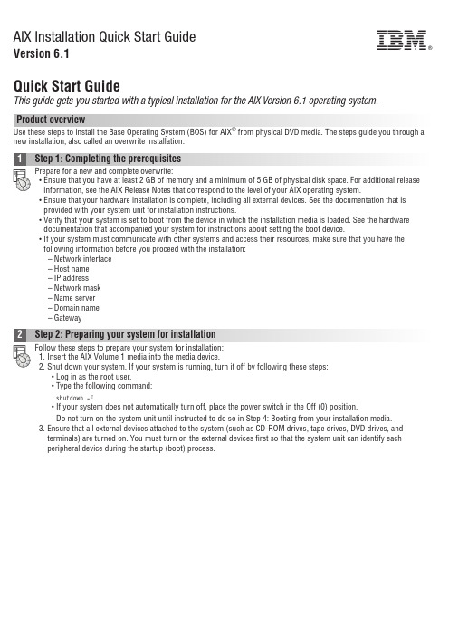
AIX Installation Quick Start GuideVersion 6.1Quick Start GuideThis guide gets you started with a typical installation for the AIX Version 6.1operating system.Product overviewUse these steps to install the Base Operating System (BOS)for AIX ®from physical DVD media.The steps guide you through a new installation,also called an overwrite installation.Prepare for a new and complete overwrite:v Ensure that you have at least 2GB of memory and a minimum of 5GB of physical disk space.For additional release information,see the AIX Release Notes that correspond to the level of your AIX operating system.v Ensure that your hardware installation is complete,including all external devices.See the documentation that is provided with your system unit for installation instructions.v Verify that your system is set to boot from the device in which the installation media is loaded.See the hardware documentation that accompanied your system for instructions about setting the boot device.v If your system must communicate with other systems and access their resources,make sure that you have the following information before you proceed with the installation:–Network interface–Host name–IP address–Network mask–Name server–Domain name–GatewayFollow these steps to prepare your system for installation:1.Insert the AIX Volume 1media into the media device.2.Shut down your system.If your system is running,turn it off by following these steps:v Log in as the root user.v Type the following command:shutdown -Fv If your system does not automatically turn off,place the power switch in the Off (0)position.Do not turn on the system unit until instructed to do so in Step 4:Booting from your installation media.3.Ensure that all external devices attached to the system (such as CD-ROM drives,tape drives,DVD drives,and terminals)are turned on.You must turn on the external devices first so that the system unit can identify each peripheral device during the startup (boot)process.If you have not set up your ASCII terminal,set the communications,keyboard,and display e the followingcriteria and your terminal reference documentation to set the communications,keyboard,and display options.The following settings are typical,but your terminal might have different option names and settings than these options: Communication Options:Options SettingsLine speed(baud rate)9600Word Length(bits per character)8Parity no(none)Number of stop bits1Interface RS-232C(or RS-422A)Line control IPRTSKeyboard and display options:Options SettingsScreen normalRow and Column24x80Scroll jumpAuto LF(line feed)offLine Wrap onForcing Insert line(or both)Tab fieldOperating Mode echoTurnaround Character CREnter returnReturn new lineNew Line CRSend pageInsert Character spaceFollow this procedure for booting from your installation media:1.Turn on the system unit power switch.2.When the system beeps twice,press5on your ASCII terminal.The word keyboard is shown when the beeps occur.3.If you have more than one console,each one might display a panel that directs you to press a key to identify yoursystem console.A different key is specified for each console that is displayed on this panel.If this panel opens,press the specified key only on the console that you want to use for the installation.(The system console is the keyboard and display device that is used for installation and system administration.)4.Select the language that you prefer to use during installation,and press Enter.1.Display the installation settings before you install the BOS,by typing2in the Choice field to select2Change/Show2.Verify the default installation settings from the Overwrite Installation and Settings panel.3.If the installation and system settings are correct,type0in the Choice field and press Enter.Confirm that theselections on the installation summary panel are correct,and press Enter to begin the BOS installation.The system automatically reboots after the system installation is complete.Go to Step9:Finishing the BOS installation.If your installation settings are not correct,or you want to change the installation settings,go to Step6.Changing the installation settings.To change the installation settings,complete the following steps:1.2.When the Change Method of Installation panel is displayed,type1New and Complete Overwrite Installation and pressEnter.When the Change Disk(s)Where You Want to Install panel is displayed,you can change the destination disk for the3.If the default settings shown are correct,type0in the Choice field and press Enter.To change the destination disk,complete the following steps:a.Type the number for each disk where you want to install the BOS in the Choice field and press Enter.Do not pressEnter a final time until you have finished selecting all disks.If you need to deselect a disk,type its number asecond time and press Enter.b.To finish selecting disks,type0in the Choice field and press Enter.The Installation and Settings panel is displayedwith the selected disks listed under System Settings.1.Type2(Primary Language Environment Settings)in the Choice field on the Installation and Settings panel.2.Select the appropriate set of cultural convention,language,and keyboard options.Most of the options are apredefined combination;however,you can define your own combination of options.3.To select a predefined Primary Language Environment,type the corresponding number in the Choice field and pressEnter.To configure your own Primary Language Environment,complete the following steps:a.Select More Choices.b.Page through the choices and select the Create Your Own Combination option.c.On the Set Primary Cultural Convention panel,type the corresponding number in the Choice field and press Enter.d.On the Set Primary Language panel,type the number in the Choice field that corresponds to your choice for theprimary language and press Enter.e.On the Set Keyboard panel,type the number in the Choice field that corresponds to the keyboard that is attachedto the system and press Enter.To verify your BOS installation settings:1.2.Press Enter to begin the BOS installation.installed.The system automatically reboots.The Installation Assistant guides you through the configuration tasks. Related informationFor more information,see the following resources:v For additional release information,see the AIX Release Notes that corresponds to your level of the AIX operatingsystem.v For late-breaking information,which might include information about the configuration process and installed software, see the readme files.v For more detailed installation notes,see the Installation and migration topic collection in the IBM®AIX6.1Information Center(/infocenter/aix/v6r1/index.jsp).AIX Version6.1Licensed Materials-Property of IBM.©Copyright IBM Corp.2012,ernment Users Restricted Rights-Use,duplication or disclosure restricted by GSA ADP Schedule Contract with IBM Corp.IBM,the IBM logo,and are trademarks or registered trademarks of International Business Machines Corp.,registered in many jurisdictions worldwide.Other product and service names might be trademarks of IBM or other companies.A current list of IBM trademarks is available on the web at“Copyright and trademark information”(/legal/copytrade.shtml).Document Number:SA23-2248-04Printed in USA。
ASUS F4A Motherboard 用户手册说明书

Quick Start GuideCopyright © 2013 ASUSTeK COMPUTER INC.All Rights Reserved.No part of this manual, including the products and software described in it, may be reproduced, transmitted, transcribed, stored in a retrieval system, or translated into any language in any form or by any means, except documentation kept by the purchaser for backup purposes, without the express written permission of ASUSTeK COMPUTER INC. (“ASUS”).Product warranty or service will not be extended if: (1) the product is repaired, modified or altered, unless such repair, modification of alteration is authorized in writing by ASUS; or (2) the serial number of the product is defaced or missing.ASUS PROVIDES THIS MANUAL “AS IS” WITHOUT WARRANTY OF ANY KIND, EITHER EXPRESS OR IMPLIED, INCLUDING BUT NOT LIMITED TO THE IMPLIED WARRANTIES OR CONDITIONS OF MERCHANTABILITY OR FITNESS FOR A PARTICULAR PURPOSE. IN NO EVENT SHALL ASUS, ITS DIRECTORS, OFFICERS, EMPLOYEES OR AGENTS BE LIABLE FOR ANY INDIRECT, SPECIAL, INCIDENTAL, OR CONSEQUENTIAL DAMAGES (INCLUDING DAMAGES FOR LOSS OF PROFITS, LOSS OF BUSINESS, LOSS OF USE OR DATA, INTERRUPTION OF BUSINESS AND THE LIKE), EVEN IF ASUS HAS BEEN ADVISED OF THE POSSIBILITY OF SUCH DAMAGES ARISING FROM ANY DEFECT OR ERROR IN THIS MANUAL OR PRODUCT.SPECIFICATIONS AND INFORMATION CONTAINED IN THIS MANUAL ARE FURNISHED FOR INFORMATIONAL USE ONLY, AND ARE SUBJECT TO CHANGE AT ANY TIME WITHOUT NOTICE, AND SHOULD NOT BE CONSTRUED AS A COMMITMENT BY ASUS. ASUS ASSUMES NO RESPONSIBILITY OR LIABILITY FOR ANY ERRORS OR INACCURACIES THAT MAY APPEAR IN THIS MANUAL, INCLUDING THE PRODUCTS AND SOFTWARE DESCRIBED IN IT.Products and corporate names appearing in this manual may or may not be registered trademarks or copyrights of their respective companies, and are used only for identification or explanation and to the owners’ benefit, without intent to infringe.E8431First Edition Model: T00CPThank you for purchasing an ASUS product! Before you start, read all the safety information and operating instructions in the User Manual bundled with your PadFone mini 4.3 to prevent injury or damage to your device.NOTE: This bundled Quick Start Guide isfor reference only and is subject to change without prior notice. For the latest updatesand additional information, please visit.23Power key 4Volume key5PadFone mini 4.3 6SpeakerCharging your PadFone mini StationFully charge your PadFone mini Station before connecting the PadFone mini 4.3.To charge your PadFone mini Station:1. Connect the USB connector into the poweradapter’s USB port.2. Connect the PadFone mini 4.3 cable toyour PadFone mini Station.3. Plug the power adapter into a wall socket.NOTES:• Use only the power adapter that camewith your ing a different poweradapter may damage your device.• Using the bundled power adapter andcable to connect your PadFone mini4.3 to a power outlet is the best way tocharge your PadFone mini Station.• The input voltage range between thewall outlet and this adapter is AC 100V- 240V. The output voltage of the microUSB cable is DC 5.2V, 1.35A.Inserting your PadFone mini 4.3 into the PadFone mini StationTo insert your PadFone mini 4.3 into your PadFone mini Station:1. Align your PadFone mini 4.3 into thePadFone mini 4.3 bay sliding track.CAUTION: We do not recommend adding a protective film or cover to your PadFone mini 4.3 as it can result in difficulty when inserting/removing the PadFone mini 4.3 to/from the PadFone mini Station.NOTE: Always keep the PadFone mini Station bay clean to prevent dust or dirt from scratching or damaging your PadFone mini 4.3.2. Insert your PadFone mini 4.3 all the way into the bay until it is securely connected to the PadFone mini Station.Your PadFone mini 4.3 briefly vibrates when the connection is secured.Removing your PadFone mini 4.3 from the PadFone mini StationGently slide the PadFone mini 4.3 out from theSafety informationPadFone mini Station care• Do not leave your PadFone mini Stationexposed to strong sunlight or excessiveheat for a prolonged period. This maydamage it.• Do not handle your PadFone mini Stationwith wet hands or expose it to moisture orliquids of any kind. Continuous changesfrom a cold to a warm environment maylead to condensation inside your PadFonemini Station device, resulting in corrosionand possible damage.• When traveling, avoid packing yourPadFone mini Station in a suitcase.Cramming the device into a suitcase maycrack the LCD display. Remember toswitch off your wireless connection duringair travel.• Use your PadFone mini Station in anenvironment with ambient temperaturesbetween -10 °C (14 °F) and 35 °C (95 °F).IMPORTANT! To provide electricalinsulation and maintain electrical safety,a coating is applied to insulate the ASUSPadFone mini Station body except on thesides where the I/O ports are located.The battery• Avoid charging in extremely high orlow temperature. The battery performsoptimally in an ambient temperature of +5°C to +35 °C.• Do not remove and immerse the battery inwater or any other liquid.• Never try to open the battery as it containssubstances that might be harmful ifswallowed or allowed to come into contactwith unprotected skin.• Do not remove and short-circuit thebattery, as it may overheat and cause afire. Keep it away from jewellery and othermetal objects.• Do not remove and dispose of the batteryin fire. It could explode and releaseharmful substances into the environment. • D o not remove and dispose of the batterywith your regular household waste. Take itto a hazardous material collection point.• Do not touch the battery terminals.CAUTION:• Risk of explosion if battery is replaced byan incorrect type.• Dispose of used batteries according tothe instructions.Prevention of Hearing LossWarning statement requirement under EN 60950-1:A12.WARNING: To prevent possiblehearing damage, do not listenat high volume levels for longperiods.NOTE: For France, headphones/earphones for this device are compliant with the sound pressure level requirment laid down in the applicable EN 50332-1: 2000 and/or EN50332-2: 2003 standard as required by French Article L.5232-1.15060-19700000。
FIFE-500 快速入门手册说明书

FIFE-500Quick-Start ManualMI 2-263 1 BINTRODUCTION ........................................................................................ 1-1 Copyright information ............................................................................................ 1-1 General information ............................................................................................... 1-1 Language ............................................................................................................... 1-1FEATURES ................................................................................................. 2-1 Display definitions ................................................................................................. 2-1 Button functions and definitions ............................................................................ 2-3 Status bar definitions ............................................................................................. 2-4OPERATION .............................................................................................. 3-1 System setup ......................................................................................................... 3-1 Auto setup configuration ....................................................................................... 3-3 Optional manual configuration ............................................................................... 3-5 Changing the guidepoint ........................................................................................ 3-6Copyright information All of the information herein is the exclusive proprietary propertyof Maxcess International, and is disclosed with the understandingthat it will be retained in confidence and will neither beduplicated nor copied in whole or in part nor be used for anypurpose other than for which disclosed.This Instruction Manual is intended to be used in addition to theFIFE-500 Web Guiding System User Manual, MI 2-262, whichcontains all safety warnings and complete customer servicecontact information.General information The instructions contained in this Quick Start Setup Manual arewritten to support operation of the FIFE -500 Web GuidingSystem.Language These are the original instructions, written in English.Display definitionsThe FIFE-500 uses a QVGA Touchscreen for Operator command inputs and status displays. This Control Panel is divided into 5 sections of information for which a brief description is listed below.Refer to the Figure 1, for the button locations in the standard, horizontal Control Panel. Also refer to the FIFE-500 Web Guiding System User Manual, MI 2-262 for complete display definitions.1.The vertical section on the left side contains the Operation Mode selection buttons(Automatic, Servo-Center, and Manual) and indicates the current Operation Modeselection by displaying the corresponding button in a green color. (Other buttons are blue).2.The horizontal section along the top, above the line, contains the status bar which alwayscontains the menu number. It may also indicate statuses, errors, and digital I/O.3.The middle section indicates the current Operation Mode, the selected sensor signal levelin a bar graph, and the level of Guidepoint Shift. This section also contains buttons for Guidepoint Shift and Guidepoint Reset.4.The lower middle section contains the Left and Right Jog buttons.5.The vertical section on the right side contains the Sensor Selection and Setup buttonsand indicates the current Sensor Mode selection by displaying the proper sensor symbol in the Sensor Select button.Figure 1.FIFE-500 CONTROL PANEL(0° AND 180° ROTATION)The Control Panel can also be configured in a vertical orientation. For the vertical orientation, the following display descriptions apply. Refer to Figure 2 for the button locations.1.The horizontal section along the top, above the line, contains the status bar which alwayscontains the menu number. It may also indicate statuses, errors, and digital I/O.2.The horizontal section near the top, just below the line, contains the Operation Modeselection buttons (Automatic, Servo-Center, and Manual) and indicates the currentOperation Mode selection by displaying that button in a green color.3.The section just below the Operation Mode buttons, indicates the current OperationMode, the selected sensor signal level in a bar graph, and the level of Guidepoint Shift.This section also contains the Guidepoint Shift buttons and the Guidepoint Reset button.4.The section below that, just above the Sensor Select and Setup buttons, contains the Leftand Right Jog buttons.5.The horizontal section along the bottom contains the Sensor Selection and Setup buttonsand indicates the current Sensor Mode selection by displaying the proper sensor symbol in the Sensor Select button.Figure 2.FIFE-500 CONTROL PANEL(90° AND 270° ROTATION)Button functions and definitions The table below gives the name along with an operational function description of each button displayed on the FIFE-500 Web Guiding System.AUTOMATIC This button initiates the Automatic mode. Correction isapplied to the web by moving the guide in response to the output ofthe sensor(s) that have been selected.SERVO-CENTER This button initiates the Servo-Center mode. Theguide is centered in its travel in response to the output of the internalServo-Center transducer.MANUALThis button initiates the Manual mode. No correction isapplied to the guide.SENSOR SELECTIONThis button is used to select the sensor(s) to beused for monitoring the web position when the system is inAutomatic mode. Sensor selection is allowed in Manual and Servo-Center modes only.SETUP This button is used to enter the Setup Menus for configuringand adjusting the guiding system.ARROWS These buttons are used to jog the guide. The direction ofguide movement is configurable.GUIDEPOINT ADJUST The two arrow buttons near the bar graph areused to adjust the System Guidepoint while in Automatic Mode orManual Mode. The button in the center is used to reset the SystemGuidepoint to the default value, which is 50% of the sensorbandwidth.BACK This menu navigation button is used to return to the previousmenu level.HOME This button is used to return to the Operator Level screen.MENU ARROWS These buttons are used in the menu system to pageforward/backward when multiple pages of menu choices areavailable. The arrows will appear disabled (grayed-out) when no morechoices are available in the respective direction.ACCEPT This button is used to save a changed value and return tothe previous screen.REJECT This button is used to discard a changed value and return tothe previous screen.Status bar definitionsThe status bar located horizontally across the top of the FIFE-500 Web Guide Operator Level screen remains visible at all times. The number on the left side of the status bar contains the numerical address of the connected motor controller. The number on the right side of the status bar indicates a hierarchical screen number. The first numerical value indicates the operation mode (1=Manual, 2=Servo-Center, 3=Automatic). The second alphabeticcharacter indicates the sensor mode (A=S1, B=S2, C=S1-S2). This screen number uniquely identifies each screen of the FIFE-500 Web Guiding System. The status bar also displays various icons, which are described on the following pages.OPERATION MODE One of these icons will appear to indicate theoperation mode of the FIFE-500 Web Guiding System. These do notappear on the Operator Level screen since the mode buttons alreadyindicate this information. These will only appear while in the setupscreens.SENSOR One of these icons will appear to indicate the currentlyselected sensor mode. These do not appear on the Operator Levelscreen since the SENSOR button already contains this information.MENU TIMEOUT The menu screens in the FIFE-500 Web GuidingSystem close automatically after 3 minutes of touch screen inactivity. The inactivity timeout option and the timeout value are configurable. The clock icons will appear during stages of the timeout process as the inactivity timer counts down. If a timeout occurs, the respective menu will abort any changes applied and return to the Operator Level screen. Some service-related screens are immune from the timeout option and are indicated by the presence of the orange clock icon.LOGIN AUTHORIZATION LEVEL When security has been configured, one of these icons will appear to indicate the authorization level of the current user. Security is disabled in the factory default configuration so these icons will not be displayed. All menu screens are accessible when security is disabled.READ ONLY MENU When security is enabled, options are available tomake menus “read only”, allowing an operator to view the settings but not change them. This icon will appear when the active menu is a “read only” menu.DIGITAL INPUT COMMAND This icon appears when a valid digital input command is present. Depending on the command, some touch panel controls may be disabled during this time. A red arrow in the down direction indicates digital input influence is disabled. A red up arrow indicates the digital outputs are disabled.GUIDEPOINT CHANGED This icon appears when a new SystemGuidepoint has been applied. This icon will appear on the status bar until the System Guidepoint remains unchanged for approximately 20 seconds.EXTERNAL LOCK This icon indicates the acceptance of the “ExternalLock” digital input command. Automatic guide movement is prohibited while in this state.ASC ON Automatic Sensor Control (ASC) is enabled for the current sensor mode. See the menu description in the FIFE-500 Web Guiding System User Manual, Figure Sheet 2-262.ASC ACTIVE Automatic Sensor Control (ASC) is enabled and the ASC state has been triggered. Automatic guide movement is prohibited. See the menu description for ASC in the FIFE-500 Web Guiding System User Manual, MI 2-262.MOTOR BLOCKED This icon indicates the motor is stalled.COMMUNICATION ERROR This error icon indicates communication is not working between the operator interface and the motor controller.VOLTAGE ERROR This error icon appears when the input voltage, motor rail voltage, or internal 12 volt power is outside acceptable range.NETWORK ERROR This icon appears when the operator interface is unable to gain network control.LINKED MODE This icon appears when the “linked mode” is active. Linked mode is used in networked systems to send the Automatic, Manual, and Servo-Center commands to all network devices simultaneously.MOTOR TYPE FAULT This icon appears when there is no motor type configured.COMMUNICATION FAULT This icon appears when a problem is detected with the communication signals. This can be caused by hardware or an addressing conflict in a networked system.LINE SPEED ZERO This icon appears when line speed control is enabled and the sensed line speed is zero. Guide correction is inhibited in Automatic mode under these conditions.MCP-05 SEEK If the MCP-05 option has been enabled, this icon will blink while a seek operation is in progress.System setupSetup screensFigure 3.FIFE-500 CONTROL PANELLEVEL 1 SETUP SCREENFigure 4.FIFE-500 CONTROL PANELSENSOR CALIBRATION SCREEN1.Connect +24 VDC Power to the input receptacle, located on the top side of theBase Assembly. Refer to MI 1-915, which is supplied with each system.2.Apply the proper power to the system.Continued next pageSystem setup3. Verify the system is in Manual Mode by pressing the MANUAL button on the Control Panel.4. Switch the system to Servo-Center Mode by pressing the SERVO-CENTER button.5. Thread the web/strip to be used, through the system and pull proper tension, ifpossible.6. Switch the system to Manual Mode by pressing the MANUAL button.7.Perform Sensor Calibration on the sensor(s) that will provide position feedback forthe web/strip. If two sensors are being used, they must be calibrated independently. Refer to Figures 3 and 4 shown on page 3-1. Be sure to use the web to be guided tocalibrate the sensor(s).a. Press the SETUP button to enter the Setup menus.b. Press the SENSOR SETUP icon to enter the Sensor Calibration menu.c. Select the desired sensor by pressing the SENSOR SELECTION button.d. Press the ‘Start Calibration’ button to begin the calibration.e.The Jog buttons at the bottom of the screen may be used to move theweb material in and out of the sensor as needed during calibration. f. Follow the instructions displayed on the Control Panel.g.When prompted to save the calibration, select YES or NO.h. Repeat this procedure for each sensor, if two sensors are to be used.i. Once this procedure has been completed, Press the ACCEPT (√) button tosave the changes.j. Press the BACK or HOME button to return to the Operator Level screen. Insimulation, these buttons are not available.Once this procedure has been performed for each sensor, it does not need to be repeated, unless the web/strip opacity has changed.Auto setup configurationNOTE: If Manual Configuration is desired, go to page 3-5.Figure 5.FIFE-500 CONTROL PANELAUTOSETUP SCREEN1.Place the web/strip in the proper position and then position the sensor(s) toalign the center of the sensor(s) bandwidth with the edge of the web/strip to beguided.2.Verify the system is in Manual Mode by pressing the MANUAL button. Refer toFigure 1 on page 2-1.Continued next pageAuto setup3. Perform Auto Setup to automatically determine the proper polarity and gain forthe system. If two sensors are being used, Auto Setup must be performed independently, in each sensor mode. Refer to Figure 3 on page 3-1 for button locations.a. Select the desired sensor mode by pressing the SENSOR SELECTIONbutton.b.Press the SETUP button to enter the Setup menus.c. Press the AUTOSETUP icon to enter the AUTOSETUP menu.d. Position the web edge near the center of the sensor proportionalband as indicated in Figure 5 on previous page.e.Press the Autosetup button to start. The guide will move a shortdistance and indicate the result as shown in Figure 6 below.Figure 6.FIFE-500 CONTROL PANELSUCCESSFUL AUTOSETUP COMPLETION4. Press the ACCEPT button to save the setting.5. Press the BACK or HOME button to return to the Operator Level Screen.6. Repeat this procedure for each sensor mode that will be used.7. Switch the system to Automatic Mode by pressing the AUTO button. This initiates the guiding function of the system. Once this procedure has been performed for each sensor mode, it does not need to be repeated.Optional manual configurationFigure 7.FIFE-500 CONTROL PANELSYSTEM GAIN SETUP SCREENSetting the gain1.Press the SETUP button to enter the Setup menus.2.Press the GAIN icon to enter the Gain menu.e the + and - ARROW buttons, or use the slider control to adjust the Gainto the desired level. (The display indicates the sensor signal stability toassist in the Gain adjustment).4.Press the ACCEPT (√) button to save the new Gain value.5.Press the BACK or HOME button to return to the Operator Level screen.Optional manual configurationFigure 8.FIFE-500 CONTROL PANEL GUIDEPOINT SETUP SCREENSChanging the guidepoint while in automatic or manual modeThe arrow controls shift the Guidepoint within the active sensor bandwidth.Press the center button near the bar graph to reset the Guidepoint to the default of 50%.Note: If the Guidepoint is changed while in Automatic Mode, the change is effectiveimmediately, but if the Guidepoint is changed while in Manual Mode or Servo-Center modes, the change is effective when Automatic Mode is initiated.NORTH, CENTRAL AND SOUTH AMERICATel +1.405.755.1600Fax +1.405.755.8425*********************EUROPE, MIDDLE EASTAND AFRICATel +49.6195.7002.0 Fax +49.6195.7002.933****************www.maxcess.euCHINATel +86.756.881.9398 Fax +86.756.881.9393 ********************.cn INDIATel +91.22.27602633 Fax +91.22.27602634 *********************www.maxcess.inJAPANTel +81.43.421.1622 Fax +81.43.421.2895 *********************www.maxcess.jpKOREA, TAIWAN, AND SE ASIATel +65.9620.3883 Fax +65.6235.4818 ********************© 2013 Maxcess。
创新CREATIVE INSPIRE T3200 quick Quick Start Guide说明书

This device complies with part 15 of the FCC Rules. Operation is subject to the following two conditions: 1. This device may not cause harmful interference, and 2. This device must accept any interference received, including interference that
Modification Any changes or modifications not expressly approved by the grantee of this device could void the user’s authority to operate the device.
Notice for Canada This Class B digital apparatus complies with Canadian ICES-003. Cet appareil numérique de la classe B est conforme à la norme NMB-003 du Canada.
may cause undesired operation.
Caution To comply with the limits of the Class B digital device, pursuant to Part 15 of the FCC Rules, this device must be installed with computer equipment certified to comply with Class B limits. All cables used to connect to the computer and peripherals must be shielded and grounded. Operation with non-certified computers or non-shielded cables may results in interference to radio or television reception.
Quick Start Guide 快速入门指南说明书

40mm screws
3mm nuts
3. Propellers
The wings silver spinners spin clockwise and the pylons black spinners spin counter-clockwise. a) Unscrew the spinner and place the 10x5 props on the main wing motors, and the 10x5R on the pylon motors. b) Tighten the spinner by holding the motor still and spinning the spinner into place. Tighten firmly with fingers.
safety switch
c) (Ai Only) Ensure that the craft has a GPS signal by checking for a blue light inside the compass unit. d) Arm the motors by holding the throttle down and right.
*Always fly at locations that are clear of building and other obstacles. *DO NOT fly above or near large crowds. *Avoid flying at altitudes above 400 ft. *Be very careful when flying 19,600 ft. or more above sea level. *Fly in moderate weather conditions with temperatures between 32° F to 104° F.
TC21快速入门指南说明书

TC21Touch ComputerQuick Start GuideCopyrightZEBRA and the stylized Zebra head are trademarks of Zebra Technologies Corporation, registered in manyjurisdictions worldwide. All other trademarks are the property of their respective owners. ©2020 ZebraTechnologies Corporation and/or its affiliates. All rights reserved.COPYRIGHTS & TRADEMARKS: For complete copyright and trademark information, go to/copyright.WARRANTY: For complete warranty information, go to /warranty.END USER LICENSE AGREEMENT: For complete EULA information, go to /eula. Terms of Use•Proprietary StatementThis manual contains proprietary information of Zebra Technologies Corporation and its subsidiaries(“Zebra Technologies”). It is intended solely for the information and use of parties operating and maintainingthe equipment described herein. Such proprietary information may not be used, reproduced, or disclosed toany other parties for any other purpose without the express, written permission of Zebra Technologies.•Product ImprovementsContinuous improvement of products is a policy of Zebra Technologies. All specifications and designs aresubject to change without notice.•Liability DisclaimerZebra Technologies takes steps to ensure that its published Engineering specifications and manuals arecorrect; however, errors do occur. Zebra Technologies reserves the right to correct any such errors anddisclaims liability resulting therefrom.•Limitation of LiabilityIn no event shall Zebra Technologies or anyone else involved in the creation, production, or delivery of theaccompanying product (including hardware and software) be liable for any damages whatsoever (including,without limitation, consequential damages including loss of business profits, business interruption, or loss ofbusiness information) arising out of the use of, the results of use of, or inability to use such product, even ifZebra Technologies has been advised of the possibility of such damages. Some jurisdictions do not allowthe exclusion or limitation of incidental or consequential damages, so the above limitation or exclusion maynot apply to you.Unpacking1.Carefully remove all protective material from the device and save the shipping container for later storageand shipping.2.Verify that the following were received:•Touch computer•PowerPrecision Lithium-ion battery•Regulatory Guide.3.Inspect the equipment for damage. If any equipment is missing or damaged, contact the Global CustomerSupport center immediately.4.Prior to using the device for the first time, remove the protective shipping film that covers the scan window,display and camera window.FeaturesFigure 1 Front ViewTable 1 Front View FeaturesNumber Item Function1Front Camera Takes photos and videos (available on some models).2Receiver Use for audio playback in Handset mode.3Proximity/Light Sensor Determines proximity for turning off display when in handset mode.Determines ambient light for controlling display backlight intensity.4Data Capture LED Indicates data capture status.Figure 2 Rear View5Charging/Notification LED Indicates battery charging status while charging and application generated notifications.6Touch Screen Displays all information needed to operate the device.7SpeakerProvides audio output for video and music playback. Provides audio in speakerphone mode.8USB-C Connector Provides USB host and client communications, and device charging via cables and accessories.9Microphone Use for communications in Handset mode.10PTT Button Initiates push-to-talk communications (programmable).11Scan ButtonInitiates data capture (programmable).Table 2 Back View Features 12NFC AntennaProvides communication with other NFC-enabled devices.13Basic Hand Strap Mount Provides mounting point for Basic Hand Strap accessory.14Battery Release LatchesPress to remove the battery.15161317141819202113142212Setting Up the DeviceTo start using the device for the first time.1.Install a micro secure digital (SD) card (optional).2.Install hand strap (optional).3.Install the battery.4.Charge the device.5.Power on the device.Installing a microSD CardThe microSD card slot provides secondary non-volatile storage. The slot is located under the battery pack. Refer to the documentation provided with the card for more information, and follow the manufacturer’s recommendations for use.CAUTION : Follow proper electrostatic discharge (ESD) precautions to avoid damaging the microSD card. Proper ESD pre -cautions include, but are not limited to, working on an ESD mat and ensuring that the operator is properly grounded.15BatteryStandard - 3,300 mAh (typical) / 3,100 mAh (minimum) PowerPrecision Lithium-ion BatteryExtended - 5,400 mAh (typical) / 5,400 mAh (minimum), PowerPrecision Lithium-ion Battery.16Volume Up/Down Button Increase and decrease audio volume (programmable).17Scan Button Initiates data capture (programmable).18Camera Flash Provides illumination for the camera.19Rear Camera Takes photos and videos.20Power Button Turns the display on and off. Press and hold to reset the device or power off.21Exit Window Provides data capture using the imager.22MicrophoneUse for communications in Speakerphone mode.1.Lift the access door.Figure 3 Lift Access Door2.Slide the microSD card holder to the unlock position. Figure 4 Unlock microSD Card Holder3.Lift the microSD card holder.Figure 5 Lift the microSD Card Holder4.Insert the microSD card into the card holder door ensuring that the card slides into the holding tabs on eachside of the door.Figure 6 Insert microSD Card in Holder5.Close the microSD card holder and slide into the lock position.Figure 7 Re-install Access DoorCAUTION: Access door must be replaced and securely seated to ensure proper device sealing.6.Re-install the access door.Figure 8 Replace Access DoorInstalling the BatteryNOTE: User modification of the device, particularly in the battery well, such as labels, asset tags, engravings, stickers, etc., may compromise the intended performance of the device or accessories. Performance levels such as sealing (Ingress Pro-tection (IP)), impact performance (drop and tumble), functionality, temperature resistance, etc. could be effected. DO NOT put any labels, asset tags, engravings, stickers, etc. in the battery well.1.Insert the battery, bottom first, into the battery compartment in the back of the device.Figure 9 Insert Bottom of Battery into Battery Compartment2.Press the battery down into the battery compartment until the battery release latches snap into place.Charging the DeviceCAUTION: Ensure that you follow the guidelines for battery safety described in the device Product Reference Guide.Use one of the following accessories to charge the device and/or spare battery.Table 3 Accessories1-Slot Charge Only Cradle CRD-TC2Y-BS1CO-01Provides device charging only. RequiresUSB-C cable (CBL-TC5X-USBC2A-01) andpower supply (PWR-WUA5V12W0xx).1-Slot USB/Ethernet Cradle CRD-TC2Y-SE1ET-01Provides device charging and communication,and charging for Extended Power Pack.Requires power supply(PWR-BGA12V50W0WW), DC line cord(CBL-DC-388A1-01), and country-specific ACline cord.4-Slot Charge Only Cradle with Battery Charger Kit CRD-TC2Y-BS54B-01Charges up to four devices and four sparebatteries. Requires power supply(PWR-BGA12V108W0WW), DC line cord(CBL-DC-381A1-01), and country-specific ACline cord.5-Slot Charge Only Cradle CRD-TC2Y-BS5CO-01Charges up to five devices. Charges up tofour devices and four spare batteries.Requires power supply(PWR-BGA12V108W0WW), DC line cord(CBL-DC-381A1-01), and country-specific ACline cord.5-Slot Ethernet Cradle CRD-TC2Y-SE5ET-01Provides device charging and providesEthernet communication for up to fivedevices. Requires power supply(PWR-BGA12V108W0WW), DC line cord(CBL-DC-381A1-01), and country-specific ACline cord.4-Slot Battery Charger SAC-TC2Y-4SCHG-01Charges up to four battery packs. Requirespower supply (PWR-BGA12V50W0WW), DCline cord (CBL-DC-388A1-01), andcountry-specific AC line cord.Cigarette Light Adapter Auto Charge Cable CHG-AUTO-USB1-01Provides power to the device from a cigarettelighter socket. Requires USB-C cable(CBL-TC5X-USBC2A-01).USB-C Communication and Charge Cable CBL-TC5X-USBC2A-01Provides UBC-A to USB-C communicationand power to the device.Micro USB Communication Cable 25-124330-01R Provides USB communication for the 1-SlotUSB/Ethernet Cradle and the USB/EthernetModule.Main Battery ChargingTo charge a device:1.Insert the device into a slot to begin charging.2.Ensure the device is seated properly.The device’s Charging/Notification LED indicates the status of the battery charging in the device. The 3,220 mAh (typical) standard battery charges from fully depleted to 90% in approximately 2.5 hours and from fully depleted to 100% in approximately three hours. The 5,260 mAh (typical) extended battery charges from fully depleted to 90% in approximately four hours and from fully depleted to 100% in approximately five hours.NOTE: In many cases the 90% charge provides plenty of charge for daily use.To achieve the best fast charging results use only Zebra charging accessories and batteries. Charge batteries at room temperature with the device in sleep mode.Spare Battery ChargingTo charge a spare battery:1.Insert the battery into a battery charging well.2.Gently press down on the battery to ensure proper contact.The Spare Battery Charging LED on the cup indicates the status of the spare battery charging. The 3,220 mAh (typical) standard battery charges from fully depleted to 90% in approximately 2.5 hours and from fullydepleted to 100% in approximately three hours. The 5,260 mAh (typical) extended battery charges from fully depleted to 90% in approximately four hours and from fully depleted to 100% in approximately five hours.Table 4 Charging/Notification LED Charging IndicatorsOffDevice is not charging. Device is not inserted correctly in the cradle or connected to a power source. Charger/cradle is not powered.Slow Blinking Amber (1 blink every 4 seconds)Device is charging.Slow Blinking Red (1 blink every 4 seconds)Device is charging but the battery is at end of useful life.Solid Green Charging complete.Solid RedCharging complete but the battery is at end of useful life.Fast Blinking Amber (2 blinks/second)Charging error, for example:•Temperature is too low or too high.•Charging has gone on too long without completion (typicallyeight hours).Fast Blinking Red (2 blinks/second)Charging error but the battery is at end of useful life., for example:•Temperature is too low or too high.•Charging has gone on too long without completion (typicallyeight hours).NOTE: In many cases the 90% charge provides plenty of charge for daily use.To achieve the best fast charging results use only Zebra charging accessories and batteries.Table 5 Spare Battery LED Charging IndicatorsSolid Amber Spare battery is charging.Solid Green Spare battery charging is complete.Solid Red Spare battery is charging and battery is at the end of useful life.Charging complete and battery is at the end of useful life.Fast Blinking Red (2 blinks/second)Error in charging; check placement of spare battery and batteryis at the end of useful life.Off No spare battery in slot. Spare battery not placed in slotcorrectly. Cradle is not powered.Charging TemperatureCharge batteries in temperatures from 0°C to 40°C (32°F to 104°F). The device or cradle always performs battery charging in a safe and intelligent manner. At higher temperatures (for example: approximately +37°C (+98°F)) the device or cradle may for small periods of time alternately enable and disable battery charging to keep the battery at acceptable temperatures. The device and cradle indicates when charging is disabled due to abnormal temperatures via its LED.1-Slot Charge Only CradleFigure 10 1–Slot Charge Only Cradle1231-Slot USB/Ethernet CradleFigure 11 1–Slot USB/Ethernet Cradle SetupTable 6 1-Slot Charge Only Cradle Features 1Power Supply 2USB-C Cable 3USB-C PortTable 7 1-Slot USB/Ethernet Cradle Features Item1DC Line Cord 2Power Supply 3AC Line Cord 4USB micro-AB Port 5USB micro-B Connector 6USB-A Connector3152464-Slot Charge Only Cradle with Battery ChargerFigure 12 4-Slot Charge Only Cradle with Battery ChargerTable 8 4-Slot Charge Only Cradle with Battery Charger Features Item1Spare Battery Charging LED 2Device Charging Slot 3Spare Battery Slot 4Power LED14325-Slot Charge Only CradleFigure 13 5-Slot Charge Only CradleTable 9 5-Slot Charge Only Cradle Features Item1Device Charging Slot 2Power LED21Figure 14 5-Slot Ethernet CradleTable 10 5-Slot Ethernet Cradle Features Item1Device Charging Slot 21000 LED 3100/100 LED213Figure 15 4-Slot Battery ChargerUSB cableThe USB cable plugs into the bottom of the device. When attached to the device the cable allows charging, transferring data to a host computer, and connecting USB peripherals.Table 11 4-Slot Battery Charger Features 1Battery Slot2Battery Charging LED 3Power LED213Figure 16 USB cableFigure 17 Imager Scanning3.Press and hold the scan button.The red laser aiming pattern turns on to assist in aiming.NOTE: When the device is in Picklist mode, the imager does not decode the barcode until the crosshair or aiming dot touches the barcode.4.Ensure the barcode is within the area formed by the crosshairs in the aiming pattern. The aiming dotincreases visibility in bright lighting conditions.Figure 18 Aiming PatternFigure 19 Pick List Mode with Multiple Barcodes5.The Data Capture LED lights green and a beep sounds, by default, to indicate the barcode was decodedsuccessfully.6.Release the scan button.NOTE: Imager decoding usually occurs instantaneously. The device repeats the steps required to take a digital picture (im-age) of a poor or difficult barcode as long as the scan button remains pressed.7.The barcode content data displays in the text field.Ergonomic ConsiderationsCAUTION: Avoid extreme wrist angles.。
DEMO9S12PFAME 快速入门指南 Rev. 1.0说明书

DEMO9S12PFAMEQuick Start GuideRev. 1.00. IntroductionThis quick start guide will walk you through setting up your demo board, connecting it to the PC, and launching the provided example. For more information, please read the demo board’s user’s manual.1. Run the Factory Programmed Example (Standalone Mode)1. Ensure that the light sensor “ENA” jumper is inserted.2. Ensure that all of the “LED ENA” jumpers are inserted.3. Ensure that the two push-button “ENA” jumpers are inserted.4. Ensure that the “RS-232/LIN SEL” jumper selects the “RS-232” position.5. Ensure that the “POWER SEL” jumper selects the “UNREG” position.6. Power on the Demonstration Board through the 12 V DC plug-in power supply.7. The green “POWER” LED on the board should turn on.8. Press the “PP0” push-button. Rotate the potentiometer. Its value will be shown on the LEDs.9. Press the "PP1" push-button. The output of the light sensor will be displayed on the LEDs.10. The value of the potentiometer or the light sensor is also sent to the RS-232 port(baud rate = 9600, data bits = 8, parity = N, stop bits = 1).2. Host ModeThe same example above can be run from the host PC. To do this, the CodeWarrior Development Tools and the SofTec Microsystems Additional Components must be installed first.Install CodeWarrior Development StudioTo install the CodeWarrior Development Studio Special Edition, insert the CodeWarrior CD-ROM into your computer’s CD-ROM drive. A startup window will automatically appear. Follow the on-screen instructions.Install SofTec Microsystems Additional ComponentsThe SofTec Microsystems “System Software” CD-ROM contains other required components to your hard drive. These components include:SofTec Microsystems DLL for DEMO9S12PFAME support;Examples;Demonstration Board’s user’s manual;Demonstration Board’s schematic;Additional documentation.To install the required components, do the following:1. Insert the SofTec Microsystems “System Software” CD-ROM into your computer’s CD-ROM drive. A startupwindow will automatically appear.2. Choose “Install Instrument Software” from the main menu.3. Click on the “Copy SofTec Microsystems DLL to \CodeWarrior for HCS12 V4.7\Prog\gdi” option. An Explorerwindow will open. Copy the “SofTec_BDM12.dll” file to your PC in the “\CodeWarrior for HCS12V4.7\Prog\gdi” folder, relative to the CodeWarrior installation path.4. Click on the “Copy examples for CodeWarrior for HCS12 V.4.7” option. An Explorer window will open. Copythe “DEMO9S12PFAME” folder to your PC, in a location of your choice. These are the examples specific for the demonstration board, and will be used later in the step-by-step tutorial.Note: to install the Additional Components on Windows 2000 or Windows XP, you must log in asAdministrator.First Connection with the PCNote: before to connect the board to the PC, it is important that you install the required system software asdescribed in the previous section.The Evaluation Board connects to a host PC through a USB port. Connection steps are listed below in therecommended flow order:1.Install all the required system software as described in the previous section. 2.Make sure the “POWER SEL” jumper is in the “USB” position. 3.Insert one end of the USB cable into a free USB port. 4.Insert the other end of the USB cable into the USB connector on the Demonstration Board. 5. The first time the Demonstration Board is connected to the PC, Windows recognizes the instrument and starts the“Found New Hardware Wizard” procedure, asking you to specify the driver to use for the instrument. Follow the wizard steps, choosing to install the software automatically when requested.The Evaluation Board’s USB driver is now installed on your system.Step-By-Step Tutorial1. Make sure that the “POWER SEL” jumper selects the “USB” position.2. Ensure that the Demonstration Board is connected to the PC (via the USB cable) and that the board is powered.3. Start CodeWarrior by selecting it in the Windows Start menu.4.From the CodeWarrior main menu, choose “File > Open” and choose the“DEMO9S12PFAME\C\Demo\Demo.mcp” file. This is the board example you copied from the SofTecMicrosystems “System Software” CD-ROM.5. Click “Open”. The Project window will open.6. The C code of this example is contained in the “main.c” file. Double click on it to open it.7. From the main menu, choose “Project > Debug”. This will compile the source code, generate an executable fileand download it to the demo board.8. A new debugger environment will open. From the main menu, choose “Run > Start/Continue”. The programwill be executed in real-time.9. From the main menu, choose “Run > Halt”. The program execution will stop. The next instruction to beexecuted is highlighted in the Source window.10. From the main menu, choose “Run > Single Step”. The instruction highlighted in the Source window will beexecuted, and the program execution will be stopped immediately after.11. From the main menu, choose “Run > Start/Continue”. The application will restart from where it was previouslystopped.TrademarksSMH Technologies is the licensee of the SofTec Microsystems trademark.Freescale™ and the Freescale logo are trademarks of Freescale Semiconductor, Inc.Copyright © 2008 SMH Technologies DC10008Microsoft and Windows are trademarks or registered trademarks of Microsoft Corporation.PC is a registered trademark of International Business Machines Corporation.Other products and company names listed are trademarks or trade names of their respective companies.。
- 1、下载文档前请自行甄别文档内容的完整性,平台不提供额外的编辑、内容补充、找答案等附加服务。
- 2、"仅部分预览"的文档,不可在线预览部分如存在完整性等问题,可反馈申请退款(可完整预览的文档不适用该条件!)。
- 3、如文档侵犯您的权益,请联系客服反馈,我们会尽快为您处理(人工客服工作时间:9:00-18:30)。
Table of contents:1INTRODUCTION (2)2KIT CONTENTS (2)3SYSTEM REQUIREMENTS (2)4GETTING STARTED (2)4.1I NSTALLATION OF NI-S ERIAL CABLE ASSEMBLY DRIVER (2)4.2I NSTALLATION OF STIM202 EVALUATION PROGRAM (3)4.3F IRST HARDWARE CONNECTION (4)4.4F IRST SOFTWARE START-UP (4)4.5I NTRODUCTION TO DIFFERENT PARTS OF PC SOFTWARE (7)4.6S AVE DATA TO FILE (8)4.7D EMONSTRATOR VIEW (9)5FILE DOWNLOAD AND CUSTOMER SUPPORT (9)6ORDERING INFORMATION (9)7REVISION HISTORY (9)Figure 1: STIM202 evaluation kitDate Sign Rev Reference Date Dok StampPrepared 100419 ROW 0 Archive 12812 100419 HKWChecked 100419 OF 1 EMApproved 100419 ROW 2 EM1 IntroductionThe STIM202 evaluation kit provides rapid measurement and configuration access to STIM202 gyro cluster fromSensonor Technologies. High data sampling frequencies, graphical presentation, and data log to file are supported for 1, 2 or 3 axes units.STIM202 requires a single voltage supply (5 VDC), and this is provided from a USB port with this setup.2 Kit ContentsKit contents:∙ Quick start manual (this document)∙ STIM202 (ordered separately, not included in the kit) ∙ Sensonor cable assembly, X-83932 ∙ NI cable assembly, X-83921∙ PC with STIM202 evaluation program (PC not included)Figure 2: STIM202 evaluation kit. Setup schematics3 System requirementsMinimum 2 free USB ports required; One for STIM202 communication, and one for STIM202 power.The STIM202 evaluation kit is supported (verified) by the following operating systems:∙ Windows Vista 32 bit ∙ Windows Xp 32 bit4Getting started4.1 Installation of NI-Serial cable assembly driverWithout connecting anything yet, install the NI-serial driver. Refer to the …Serial Installation Guide‟ sheet and CR-ROM in the included NI-serial driver box (X-83921) for instructions. During installation the following windows appear:Figure 3: NI-Serial installation (1 of 12)Figure 4: NI-Serial installation (2 of 12)Figure 5: NI-Serial installation (3 of 12). Selections can be left as default.Figure 6: NI-Serial installation (4 of 12)Figure 7: NI-Serial installation (5 of 12)Figure 8: NI-Serial installation(6 of 12)Figure 9: NI-Serial installation (7 of 12)Figure 10: NI-Serial installation (8 of 12)Figure 11: NI-Serial installation (9 of 12)Figure 12: NI-Serial installation (10 of 12)Figure 13: NI-Serial installation (11 of 12)Figure 14: NI-Serial installation complete (12 of 12)4.2 Installation of STIM202 evaluation program∙ Download the latest version of …Evaluation Kit STIM202 v.x.y .zip‟ from Sensonor FTP server (see chapter 5 for login details etc.). Consider the feature …Open FTP site i n Windows explorer‟ in the web browser if that is more convenient than the default view∙ Pack out the content of the zip-file to a local drive∙Run the installation file (setup.exe) and follow the on-screen instructionsFigure 15: PC software installation from a local driveDuring installation the following windows appear:Figure 16: PC software installation (1 of 6)Figure 17: PC software installation (2 of 6)Figure 18: PC software installation (3 of 6)Figure 19: PC software installation (4 of 6)Figure 20: PC software installation (5 of 6)Figure 21: PC softwareinstallation complete (6 of 6)4.3 First hardware connectionNI-Serial driver and PC software should already be installed at this point.Now, proceed to connect system hardware as follows:∙Connect a STIM202 to the Nicomatic connector of the STIM202 cable assembly. A small screw driver is needed for this (to rotate the fixing screws of the Nicomatic connector)∙Connect the 9 pin D-SUB connector on the opposite side of the STIM202 cable assembly to the NI cable assembly∙Insert the USB connector of the NI cable assembly in a free USB port of the PC. Verify that the device driver installation is completed successfully. The NI-Serial device should now be visible in device manager. Notice the COM-port numberFigure 22: Verification that NI USB-485 device is visible in device manger after first hardware connection ∙Leave the second USB connector (the one powering STIM202) unconnected at this point4.4 First software start-upProceed to first time start-up of PC software as follows:∙Navig ate to, and click on, …STIM202 Evaluation‟ in the Windows start menuFigure 23: Start-up of PC software from Windows start menu∙ A pop-up box will appear and ask for a parameter file (an .INI-file). Select the one available by default, called…STIM202 evaluation.INI‟Figure 24: INI-file selection at startup of PC software∙The software user interface appears after selecting the INI-fileFigure 25: User interface of PC software directly after startup∙Now, open PC serial connection to STIM202 evaluation kit hardware by clicking on …Connect to HW‟. A green light appears, and the message …Hardware connected OK‟ is shown in the lower right corner of the panel.Note: The COM-port in use is likely to be different from the default one of the parameter file (default is COM4) if the connection fails (indicated by red LED). If this is the case, the parameter file needs to be edited, and this can be done from the …Parameters‟ panel. Password to enable edit is …stim‟. See also Figure 34 showing the …paramters‟ panel. (Hint: Use the device manager to find the correct COM-port if this has to be changed to something different then the default value)Figure 26: Hardware connection OK∙Switch the ‟Apply voltage‟ control to ‟ON‟ and proceed to insert the USB connector for powering STIM202 intoa free USB port. Confirm voltage applied by clicking …OK‟ in the pop-up panel appearing (telling …Turn power(5.0V) to STIM ON‟). (This rather manual process controls some operations of the PC software.)Figure 27: Confirm power by USB is applied to STIM202∙Verify that the connection is established to STIM202 by asking for a …config DG‟. Thi s should look similar to below:Figure 28: Result of sending ’Request config DG’ to STIM202 The kit is now ready for use4.5 Introduction to different parts of PC softwareIn addition to what already has been shown, some functions and panels are available in PC software: Figure 29: Result of sending ’Request identity DG’Figure 30: Result of sending ’Request serial DG’Figure 31: After entering ’Service mode ’. Note that the ‘Enter Serv. mode’ button is activated from ‘Normal mode’ panel , and the that return to Normal mode is done by clicking ‘Exit to normal mode’Figure 32: ’Measure’ panel showing result of hands-on test (x, y and z axes are shown)Figure 33: ’Demo’ panel showing result of 3-axis hands-on test (x, y and z axes are shown)Figure 34: ’Parameters’ panel4.6 Save data to fileTest data can be logged to file from the …measurement panel‟ …by clicking “Save to f ile” button. Timetags and data with units, [s] and [°/s] respectively, are listed in this txt-file.Figure 35: Result file with time tags and measurement data4.7 Demonstrator viewA demonstrator part of the software is found i n the …demo‟ panel. Various reset times and axis scales can be selected. The STIM202 axes rate signals are handled and plotted axis by axis real-time in these windows. Curves shown are angular rate [°/s] in red, and increment angle [°] in blue.5 File download and customer supportCheck for the latest update of the STIM202 evaluation kit software package on Sensonor FTP server, or by addressing Sensonor customer support with an email to: customer.support@sensonor.noFTP server details:FTP address: ftp://195.1.76.74User name: senPassword: senFigure 36: Sensonor FTP server login6 Ordering informationExtra STIM202 cable assemblies (X-83932), and NI-serial cable assemblies (X-83921), are also available up-on request.7 Revision history。