QS-T280M3[DS]
清华同方空调电子样本

户式中央空调SG商用风管道式中央空调制冷量:7。
3KW—26.9KW适用范围:70—10000平方米茶楼、餐馆、娱乐、超市、展厅、生产车间等大面积、人流密集的场所.机组特点舒适健康◎可直接从户外引入新风,改善室内空气品质,且没有冷却水系统被污染的担忧,彻底摆脱军团菌的危害,可有效预防空调病。
功能完备◎六种基本运行模式;四种风速挡调节体感温度;红外线远距离遥控,蜂鸣声响提示;12小时内开关机智能设置更具人性化。
静音设计◎采用低噪音风机及先进降噪结构设计,工作噪音远低于国家标准,充分保证室内机组运行安静、平稳.灵活设计◎送回风口自由配置,款式任意选择,可满足众多用户的不同室内装潢风格。
安装便捷◎室内机直接隐蔽安装在天花板内,风管道布置简单,无需水泵、水管道和阀门等冷水系统,设计周期短、安装灵活、维护方便。
◎单程30m超长室内外机组连接配管,使得空调机组安装位置更加随意.室外机机组性能参数配套室内机暗藏吊顶式室内机组性能参数水管道式户式中央空调HA水管道式户式中央空调制冷量:9。
7KW-46KW适用范围:80m2—600m2的公寓、别墅、小型商用和工业用空调场合。
机组特点健康舒适◎具有温差小,风量大的特点;以水调节温度,使室内空气更柔和,与人体感觉舒适温度曲线完美结合,完全避免传统家用空调冷热不均引起的空调病,老人与儿童同样可以安全享受。
技术先进◎独特节流设计配合专用控制软件,精确控制温度;采用动态除霜技术,降低系统压力,减小温度波动◎专利技术排水方式,杜绝化霜水结冰,排除隐患。
设计灵活◎可与城市热网、燃气炉、电加热、地板采暖等设备配合.◎主机根据结构不同分为立式、卧式、分体式,不仅简化安装,更利于管路设计和建筑物外形美观,分体式还可满足重霜区域、高寒地区等全国范围内不同气候地区使用。
智能控制◎网络智能远程监控系统,通讯遥控系统对空调的启停、温度、时间等进行控制调节,联动功能更可实现室内风机盘管对主机的启停控制,使温度更精准、节能更有效。
麦克维尔产品手册

750
800
800
850
850
900
950
1000
1100
1200
1300
输入功率
kW
447.3
462
489.1
504.5
518.5
526.4
558.4
587.5
619.9
680.1
759
824.7
电源
380V/3N〜/50Hz
注:■ 以上选型适用于冷冻水进/出水温度为 12℃/7℃,冷却水进/出水温度为 32℃/37℃,换热器流程数为 2 流程。
40 热泵热水机组
模块式空气源热泵热水机组MHA
42 末端空调机组
组合式空气处理机组 MDM 洁净室用空气调节机组 MDX 单壁柜式空气处理机组 MSW 双壁柜式空气处理机组 MDW 超薄吊顶式空气处理机组 MHW 卧式暗装风机盘管 MCW 立式暗装风机盘管 MFCW 立式明装风机盘管 MFMW 天花嵌入式风机盘管 MCKW 卧式明装风机盘管 MCMW 吊顶式全热热回收新风机组 HRB
79 轻型商用空调机组
天花嵌入式分体空调器 MCK-T 明装吊顶/座地式分体空调器 MCM-D 暗装吊顶式分体空调机组 MCC-T 风冷冷风/热泵型管道式空调机 MDB“T”系列 风冷冷风/热泵型管道式空调机 MDB“M”系列 风冷冷风/热泵型管道式空调机 MDB“S”系列 “旋风”系列水冷柜机 MWCP 屋顶式空调机组 MRT
SMC数字流量开关操作手册说明书
Digital Flow Switch (Display Part) Operation Manual For AirPF2A300/301 SeriesPF2A310/311 SeriesFor Pure Water/Chemical Fluid PF2D300/301 SeriesFor WaterPF2W300/301 SeriesPF2W330/331 SeriesURL SAFETY2Model Indication Method4Name and Functions of Individual Parts 6Installation7Outline with Dimensions8Example of Internal Circuit and Wiring 9Setting 10Initialize11Display Function of Integrated Flow Rate Value 15Instantaneous Flow Rate Setting Mode16Integrated Flow Rate Setting Mode 19Output Selection 20Other Functions 23Specification24CONTENTSThank you for purchasing the SMC PF2*3**Series Digital Flow Switch.Please read this manual carefully before operating digital flow switch and understand digital flow switch, its capabilities and limitations.Please keep this manual handy for future reference.OPERATOR•This operation manual has been written for those who have knowledge of machinery and apparatus that use pneumatic equipment and have full knowledge of assembly, operation and maintenance of such equipment.•Please read this operation manual carefully and understand it before assembling, operating or providing maintenance service to the flow switch.32NOTEFollow the instructions given below when handling your flow switch.Otherwise, the switch may be damaged or may fail, thereby resulting in malfunction.•Do not drop it, bring it into collision with other objects or apply excessive shock (490m/s 2or more).•Wiring correctly.•Do not wiring while power is on.•Although the flow switch complies with the CE Marking, since it does not have the thunder serge protection, please carry out protection to thunder serge by the equipment side.•Although the flow switch complies with the CE Marking, since the equipment and apparatus which are made to generate the serge (Electro-magnetic lifter, High frequency induction furnace, Motor etc.) around the flow switch should perform measure against serge come out.•Do not use with power cable or high-voltage cable in the same wire route.•Do not use in a place in which water, oil, or a chemical splashes.•Do not push the setting buttons by a sharply pointed object.•Turn on the power supply of a flow switch for Air, when flow is zero.Some initial drift occurs during ten minutes after turning the power on.•Start measurement by the flow switch three seconds after turning on the power. (Also in momentary interception of the power supply by reset etc.) Please take a measure by the program of equipment etc.•Maintain the switch status for measurement output before setting when initializing or setting a flow rate of the flow switch.Measure after checking impacts to the equipment.Carry out a setup since a control system is shut down if required.The Digital Flow Switch and this manual contain essentialinformation for the protection of users and others from possible injury and property damage and to ensure correct handling.Please check that you fully understand the definition of the following messages (signs)before going on to read the text, and always follow the instructions.Please read the operation manuals of related apparatus and understand it before operating the flow switch.Do not disassemble, remodel (including change of printed circuit board) or repair.An injury or failure can result.Do not operate beyond specification range.Fire, malfunction or switch damage can result.Please use it after confirming the specification.Do not operate in atmosphere of an inflammable, an explosive and corrosive gas.Fire or an explosion can result.This flow switch is not an explosion-proof type.54NOTE 1:The new Measurement Low prohibits use in Japan of flowswitches with a unit selection function.NOTE 2:Fixed unit for instantaneous flow rate is :L/minfor integrated flow rate is :LSeparate Type Display PartA : AirD : Pure Water/Chemical Fluid W : Water•About sensor partThe type of the sensor part combined with a display part is indicated to be PF *5**with this manual.Refer to the following correspondence table for the sensor part type combined with each display part.BodyOutput (OUT1) Lamp (Green):Lit when OUT1 is ON. Flickers when an overcurrent erroroccurs.Output (OUT2) Lamp (Red):Lit when OUT2 is ON. Flickers when an overcurrent erroroccurs.LED Display:Displays a flow rate, set mode status, selected display unitand error code.Button (UP): Selects a mode and increases a set ON/OFF value.Button (DOWN): Selects a mode and decreases a set ON/OFFvalue.Button (SET): Changes the mode and sets a set value. RESETPressing the and buttons simultaneously will activate the RESET function.Use this function to clear errors when a trouble occurs.Panel Mount Adapter type ZS-22-EPanel Mount Adapter APanel Mount Adapter BBracket are includedMounting•Install the Display Part on the panel, once the Panel Mount Adaptor Bremoves.•Insert Panel Mount Adapter B supplied as an accessory intoSection A of Panel Mount Adapter A.Push Panel Mount Adapter B from behind till the display is fixedonto the panel.The pin of Panel Mount Adapter B engages the notched part ofPanel Adapter A to fix the display.•The switch can be mounted on a panel with a thickness of 1.0 to3.2mm.•See the illustration below for panel cut dimensions.Panel Cut Dimensions Accessories LED DisplayLamp (Red)SETButton (UP)7 698++0.5Panel Thickness: 1 to 3.2mmPanel Cut DimensionsOutput SpecificationBe sure to select a sensor in SMC PF *5**series for accurate measurement of flow rates.The display outputs only switch output.Analog output is output directly by the sensor part. See theoperation manual of the sensor part for the complete information. Connection•Turn the power off before making connection.•Install the cable separately from the route for power cable or high-voltage cable. Otherwise, malfunction may potentially result due to noise.•Use compression terminals for connection to the terminal board.See the full view of dimensions diagram for details of the terminal board.–0NPN Open Collector Output 2OutputsMax. 30V, 80mAInternal Voltage Drop 1V or less–1PNP Open Collector Output 2Outputs Max 80mAInternal Voltage Drop 1.5V or lessPF ∗5 SeriesPF ∗5 SeriesSetting ProceduresKeep pressing the button longer than two seconds. Remove the finger off the button when one of the characters of LED display column of the following table is displayed.1. Flow Rate Range SettingPress the button and select the flow rate range.Press thebutton to set.2. Display Mode SettingSelect whether to display instantaneous flow rate orintegrated flow rate.To change the Display mode, press thedesired flow rate to display. Then press the button.[d_1] and [d_2] respectively indicate the instantaneous flow rate and integrating flow rate.11103. Selecting Display Unit(In case [-M] is not assigned to unit specification in model indication) Refer to page 14.4. Output Method SettingThree output methods are available, namely, instantaneous switch, integrating switch and integrating pulse. The method for output to OUT1 or OUT2 is set as follows.1)First, the output method for OUT1 is set.*Press the button and select the instantaneous switch,integrating switch or integrating pulse.*Press the button to set.[o10] [o11] and [o12] respectively indicate the2)Select one output method for OUT2 from three output methods by pressing the button, as in OUT1.*Press the button to set.[o20] [o21] and [o22] respectively indicate theinstantaneous switch, integrating switch and integrating pulse.5. Output Mode SettingTwo output modes are available, namely, the Reverse Output modeand Non-Reverse Output mode. An output mode for OUT1 andOUT2 is set.1)First, the output method for OUT1 is set.*Press the button and select the Reverse Output mode or Non-Reverse Output mode.*Press the button to set.[1_n] and [1_P] respectively indicate the Reverse Outputmode and Non-Reverse Output mode.mode and Non-Reverse Output mode by pressing the button,as in OUT1.*Press the button to set.[2_n] and [2_P] respectively indicate the Reverse Outputmode and Non-Reverse Output mode.13 1215•Press the button first, then the button, to press both buttons simultaneously. Integration starts when [–] flickers.•Lower three digits of an integrated value are always displayed.Press the button when wishing to check upper three digits.•Pressing the button enables to display an instantaneous flow rate even during integration.•To stop integration, press the button first, then the button,to press both buttons simultaneously.The display will keep the present integrated value.To clear display of an integrated value, press both the and buttons simultaneously longer than two seconds.To further continue integration from the saved value, repress thebutton first, then the button, to press both buttons simultaneously.1716Manually set an actuation value of the instantaneous-value switch in case the instantaneous switch is selected in initialization.The output method is also set in accordance with the value set manually. Set the output method while referring to the output method described below.1.Keep pressing the button and remove the finger off when [F-1] is displayed.2.Repress the button to set for input of a set value in [n_1] (P_1 in the Non-Reverse Output mode) for OUT1.In case the Reverse Output mode is selected in initialization, [n_1]and the set value will be displayed alternately.(In case the Non-Reverse Output mode is selected in initialization,[P_1] and the set value will be displayed alternately.) 3.Press the or buttons to select a desired set value.Press the button to increase the set value or the button to decrease the set value.4.Press the button to set the set value and to move to the setting mode for [n_2] (P_2 in the Non-Reverse Output mode).In case the Reverse Output mode is selected in initialization, [n_2]and the set value will be displayed alternately.(In case the Non-Reverse Output mode is selected in initialization,[P_2] and the set value will be displayed alternately.) 5.Press the or buttons to select a desired set value.Press the button to increase the set value or the button todecrease the set value.6.Press the button to set the set value and to move to the setting mode for OUT2.Set the set value as in OUT1.In case the Reverse Output mode is selected for the OUT2 setting in initialization, [n_3] or [n_4] and the set value will be displayed alternately.In case the Non-Reverse Output mode is selected in initialization,[P_3] or [P_4] and the set value will be displayed pleting settings for [n_1] to [n_4] ([P_1] to [P_4] in the Non-Reverse Output mode) will finish flow rate setting and the mode will return to the Measurement mode.Manual1918The flow rate flowing through the flow switch will be set as areference value and a Hysteresis (H) will be set automatically at a value 3digits lower when setting auto preset input.The output method for setting by auto presetting is only hysteresis mode.1.Keep pressing the button and remove the finger off when [F_1] is displayed.2.Press the button and change [F_1] in the display to [F_2].3.Press the button and set the auto preset state of OUT1.The display will change to show [AP1] .(In case OUT1 setting is not needed, press the and button simultaneously.)4.Prepare the equipment to set the flow rate of OUT1 and flow fluid of the required flow rate.5.Pressing the button will automatically read the flow rate. A value 3digits lower will be set automatically as a Hysteresis (H).The display will show [A1L] and the set value alternately.6.Press the button and set auto preset state of OUT2.The display will change to show [AP2].(In case OUT2 setting is not needed, press the and buttons simultaneously.)7.Prepare the equipment to set the flow rate of OUT2 and flow fluid of the required flow rate.8.Pressing the button will automatically read the flow rate. A value 3digits lower will be set automatically as a Hysteresis (H).The display will show [A2L] and the set value alternately.9.Press the button to finish the Auto Presetting mode and themode will return to the Measurement mode.Auto Presetting•The switch is set to an integrated flow rate.•Integrated flow rate is displayed by switchingdividing into lower three digits and upper three digits. 1.Keep pressing the button and remove the finger off when [F_1] or [F_3] is displayed.Proceed to Step 3. if [F_3] is displayed.([F_1] will be displayed in case the instantaneous switch is selected for any switch output in initialization. In other cases,[F_3] will be displayed.)2.When [F_1] is displayed, push the button till the display shows [F_3]. The subsequent setting operation will be the same as that when [F_3] is displayed. Set as follows.3.Set as follows if [F_3] is displayed.1)Press the button and display the lower three digits of the integrated flow rate of OUT1.2)Press the or buttons and adjust the set value to the desired value.3)Press the button to set. The upper three digits of OUT1 will be displayed.4)Press the or buttons and adjust the set value to the desired value.5)Press the button to set. The lower three digits of OUT2 will be displayed.6)Press the or buttons and adjust the set value to the desired value.7)Press the button to set. The upper three digits of OUT2 will be displayed.8)Press the or buttons and adjust the set value to the desired value.9)Press the button to finish setting of an integrated flow rate and the mode will return to the Measurement mode.Instantaneous Switch Output MethodFour output methods can be selected by selecting an output modeOne of these four output methods can be selected for each output.•OUT1 and OUT2 can be set independently.•1digit flow rate conversion will be a minimum set unit. See thespecification for the set flow rate units.•When setting in the Auto Presetting mode, the Hysteresis mode willbe set automatically. Hysteresis in this case will be 3digits fixed.•In the Window Comparator mode, leave between [P_1] and [P_2]or between [n_1] and [n_2] values more than seven digits.•The following is given using OUT1 as an example. Thedescriptions for OUT2 are the same as those for OUT1, under theconditions that [n_1] and [n_2] should be replaced by [n_3] and[n_4] and [P_1] and [P_2] should be replaced by [P_3] and [P_4].20212322To reset display of Error 1, 2 or 4, press theandbuttons simultaneously.Integrating Switch Output•Two output methods can be selected by selecting an output mode.One of these two output methods can be selected for each output.•OUT1 and OUT2 can be set independently.•The following is given using OUT1 as an example. Thedescriptions for OUT2 are the same as those for OUT1, under the conditions that 1nL and 1nH should be replaced by 2nL and 2nH and 1PL and 1PH should be replaced by 2PL and 2PH.Integrating Pulse Output•Pulse output for integrated flow rate measurement.Key Lock FunctionThis function prevents errors such as changing a set value by mistake.Lock•Keep pressing the button longer than three seconds.The display will change to show [F_1] Æ[***] Æ[unL.]Remove the finger off the button when [unL] is displayed.([***]:Refer to the LED display column in the table, Page11)•Press the button to set the display to [Loc]•Press the button and return to the Measurement mode.Unlock •Press the button longer than three seconds. Remove the finger off the button when [Loc] is displayed.•Press the button to change the display to [unL]•Press the button and return to the Measurement mode.Error Display and TroubleshootingIn case an error occurs, take the following actions:2524*1:The flow rate indication range is corresponding to the flow rate range set up bythe initialization.*2:With a unit selection function(Without a unit selection function, fixed to SI units(L/min or L))*3:Two units in normal condition (0˚C/ 101.3kPa) or standard condition (20˚C/101.3kPa/ 65%RH) can be selected.*4:This is an overall accuracy combined with PF2A 5**.*5:Select whether to switch output or pulse output of integrated flow rate by theinitialization.*6:Window Comparator mode. Hysteresis (H) will be in 3digits.Separate [P_1] and [P_2], as well as [n_1] and [n_2], more than 7digits.(In case of the output 2, n_1,2 becomes n_3,4 and P_1,2 becomes P_3,4)*7:The display part conforms entirely to the CE standard.2627。
高速公路工程试验项目及频率一览表
高速公路工程试验项目及频率一览表序号项目检验内容采用标准抽样频率取样方法1 土工颗粒分析界限含水量试验 JTJ051-93《公路土工试验规程》JTJ033-95《公路路基施工技术规范》每5000m3 一次取具有代表性的扰动土。
击实试验室内CBR试验每种土质每2万m3 一次2 细集料筛分表观密度与堆积密度含泥量及泥块含量含水率 JTJ058-2000《公路工程集料试验规程》以进场数量为一检验批,每检验批代表数量不得超过400m3 取样前先将取样部位表层铲除,然后由各部位抽取大致相等的砂,组成一组样品。
3 粗集料筛分含泥量及泥块含量针片状含量压碎值 JTJ058-2000《公路工程集料试验规程》每批次进场检验一次,每检验批代表数量不得超过400m3 先铲除表面处无代表性的部分,然后在料堆的顶部、中部、底部取得大致相等诉若干份组成一组试样。
表观密度与堆积密度洛杉矶磨耗值磨光值必要时做4 水泥细度标准稠度用水量凝结时间安定性胶砂强度 GB/T1346-2001《标准稠度用水量、凝结时间、安定性检验方法》GB175-1999《硅酸盐水泥、普通硅酸盐水泥》12958-1999《复合硅酸盐水泥》GB17671-99《水泥胶砂强度》GB1345-91《水泥细度检验方法》每批次进场检验一次,每检验批代表数量不得超过200t,散装500t。
从20个以上的不同部分取等量样品作为一组试样,样品总量至少12kg。
5 粉煤灰细度需水量比烧失量、三氧化硫含水量抗压强度比 GB1345-91《水泥细度检验方法》GB1596-91《用于水泥和砼中的粉煤灰》GB/T76-96《水泥化学分析试验》GBJ146-90《粉煤灰应用技术规范》每批次进场检验一次,每检验批代表数量不得超过200t。
从每批中任抽10袋,每袋取试样不少于1kg,混拌均匀后按四分法取样两份,一份试验,一份封存留样,每份重量大于3kg。
高速公路工程试验项目及频率一览表序号项目检验内容采用标准抽样频率取样方法6 焊接钢筋闪光对焊拉伸闪光对焊弯曲电弧焊 JGJ27-86《钢筋焊接接头试验方法》JGJ18-96〈钢筋焊接及验收规程》以300个同接头型式、同钢筋级别的接头作为一批。
80寸一体机招标参数

52、软件自动永久免费升级
G、产品资质
1、产品获得中国国家强制性产品认证证书(3C认证)
2、产品获得职业健康安全管理体系认证证书
3、产品获得环境管理体系认证和质量管理体系认证证书
H、售后服务
1、▲加入中国联保,企业有固定400专线服务电话(提供中国联保-CUG证书)
8、画面显示尺寸1790x1015MM(显示电脑画面与液晶屏尺寸一致)
9、色彩度≥16.7M色
10、亮度≥360 cd/m2
11、对比度≥5000:1
12、可视约等于178度
13、▲输入接口≥1路AV/音频、≥1路VGA/音频、≥1路YPbPr/YCbCr/音频、≥1路TV、≥2路HDMI(一路前置HDMI),≥9路USB(5路前置USB)
14、输出接口≥1路耳机; ≥1路SPDIF;≥ 1路AV
15、立安装
17、音/视频接入方式 电脑采用HDMI传输音频和视频(全数字模式),并且具备侧面VGA模拟输出,可外接投影仪设备,实现镜像功能;外接电脑采用VGA、HDMI等多种接入方式
18、功耗 工作≤270W,待机≤1W
2、▲一体机厂家为中国教育装备行业协会会员,并获得中国教学装备行业售后服务先进单位证书
3、免费提供原厂电脑配件,免费保修一年,终身维护。48小时内维护响应。
E、电子白板交互软件功能要求
1、▲书写、绘图功能:(需提供软件产品登记证书及电子白板软件软件著作权证书)
2、支持6点或以上书写,实现多人同时书写;
3、自定义界面,可拖放常用工具到快捷栏,也可以创建用户名保存界面设置;
4、有外部工具扩展栏,方便添加其他应用到本软件中使用;
5、课前备课功能,支持在其他计算机上备课后导入到本地计算机演示;
波士顿家用电器官方网站商品说明书

Accessories: To purchase Bosch accessories, cleaners & parts please visit /us/store or call 1-800-944-2904 (Mon to Fri 5 am to 6 pm PST, Sat 6 am to 3 pm PST).SHXM78Z54N Black Stainless Steel Also available in:Stainless Steel SHXM78Z55N White SHXM78Z52N BlackSHXM78Z56NPatented CrystalDry™ technology transforms moisture into heat to get dishes, including plastics, 60% drier.142 dBA: dishwasher runs quietly so your kitchen conversations aren’t interrupted.The Flexible 3rd Rack with fold down sides adds 30% more 2 loading area, perfect for utensils and ramekins.The AquaStop® leakprotection system contains leaks through a precisely engineered system. If a leak occurs, the system contains it by shutting down operation andpumping out water. So you have the ultimate peace of mind whether you are away or at home.1Based on aggregate average drying performance of Bosch Dishwashers with CrystalDry on combined household load including plastics, glass, steel, and porcelain as compared to Bosch Dishwashers with PureDry. Drying performance may vary by dish type.2Compared to a Bosch dishwasher with 2 racks.3Certification to NSF/ANSI Standard 184 for residential dishwashers. 4September 2020 running production change to remove adhesive routing clips for power cord. These clips and the edge protector are now included in the dishwasher accessory kit # SMZEPCC1UC.Accessories: To purchase Bosch accessories, cleaners & parts please visit /us/store or call 1-800-944-2904 (Mon to Fri 5 am to 6 pm PST, Sat 6 am to 3 pm PST).Installation DetailsJunction box accessoryInstallation DetailsAccessories: To purchase Bosch accessories, cleaners & parts please visit /us/store or call 1-800-944-2904 (Mon to Fri 5 am to 6 pm PST, Sat 6 am to 3 pm PST).。
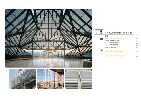
法国尚飞电动百叶翻板及电动开窗机产品手册
宜达纯真单频道发射器(Telis 1 Pure)
1810630
单频道发射器,频率433.42MHz
· 纯白外观设计,适用于多数装饰风格
· 手持使用,在房间任意位置遥控自如
· 悠然系列
白银系列
1810649
1810637
宜立单控开关(Inis Uno)
电动百叶翻板以推杆开窗电机(如Rodeo)或管状电机(如LT)驱动,一般只能做到调节翻板角度而不能收合。使 用两套管状电机系统目前可以实现百叶翻板的收合。
夏天
冬天
遮阳采光
保温节能
使用尚飞animeo控制系统,可以实现百叶翻板的光跟踪,并结合光、风、雨、温度等气候感应器,实现自动控制。 详细请咨询尚飞。
(单电机)
〔8-5〕
〔8-6〕
Micro Kit+ 链式开窗机
最大400 mm 最大250 N 25mm /s
过电流停止式 IP 20 黑色 / 灰色 / 白色
400mm (单电机)
250 N
(含配件)*
2700810 Micro Kit+ max 400mm - 黑色 2700811 Micro Kit+ max 400mm - 灰色 2700812 Micro Kit+ max 400mm - 白色
变压器
24VDC
Centralis DC IB 宜心直流型总线分控开关
1810153
尚飞提示
翻板及开窗机可以直接并联,一个开关能控制的电机数量与荷载电流有关
〔8-8〕
百叶翻板及开窗机可选控制器
多功能无线电接收器(Universal RTS Receiver )
思默康产品选型说明书

温度湿度气体2015价格表德国标准 东方精神壓力照度及位移思默康自动化设备(上海)有限公司价格生效期始于2014年10月15日1.0版TRW1-Series (T)TRW2-Series (T)0…10V / 4…20mANTC / PT / NiTPS1-Series (T)0…10V / 4…20mANTC / PT / NiTOW1-Series (T)TOW2-Series (T)TDE1-Series (T_av)TDE2-Series (T_av)风管温度防凍开关TDE2-Series (T_fp)通用温度有源传感器TUU1-Series (T)0…10V / 4…20mA通用温度无源传感器TUU2-Series (T)HPS2-Series (H_cs) HPS2-Series (H_lg)GDI1-Series (VOC)0…10V湿度:0..10V温度:0..10V可选 NTC ; PT ; NiPDE1- Series (dP_r) PDI1- Series (V&T) PDE2- Series (dP) PPE1- Series ( PPE2- Series (LRC1-Series(L)10V / 4…20mA CRC8-series (L&M)照度:0...10V人体活动:ON/OFF MRW2-Series(M)asia pacific照度及位移传感器温度湿度气体壓力照度及位移价格生效期始于2014年10月15日价格表其他配件德国标准 东方精神asia pacific配件asia pacific安装套件思默康自動化設備(上海)有限公司上海市閔行區莘庄工業區春東路479號C-1廠房2樓電話: (+8621) 5176 0211傳真: (+8621) 5176 0213泰慕康传感器科技有限公司香港新界荃灣168德士古道德豐工業中心2座13/樓10-11室電話: (+852) 3468 8636傳真: (+852) 3621 0002网站: / 邮箱: info@ asia pacific声明该价格表中,对技术信息都进行了简化,并保持随时更新。
- 1、下载文档前请自行甄别文档内容的完整性,平台不提供额外的编辑、内容补充、找答案等附加服务。
- 2、"仅部分预览"的文档,不可在线预览部分如存在完整性等问题,可反馈申请退款(可完整预览的文档不适用该条件!)。
- 3、如文档侵犯您的权益,请联系客服反馈,我们会尽快为您处理(人工客服工作时间:9:00-18:30)。
6. 驱动流程
6.1 Software Flow
6.2 Register Settings /*
Reference LCD Controller Datasheet and lcd_driver.c/ lcd_driver.h File; */
产品数据手册
7 / 14
液晶显示模块 V1.00
■■奇烁电子
QS-T280M3
7. 控制时序
7.1 i80-System Interface Timing Characteristics for LCD
产品数据手册
8 / 14
液晶显示模块 V1.00
■■奇烁电子
QS-T280M3
7.2.Serial Interface Timing Characteristics for TouchPanel Controller(ADS7843)
——————————————订购信息 型号 QS-T280M3 规格 含TP及驱动 其它 标配
———————————————————————————————————实物图片
1 / 14
■■奇烁电子
QS-T280M3
目
1. 2. 3. 4. 5. 6. 7. 8. 9.
录
模块参数.....................................................................................................................................................3 电气特性.....................................................................................................................................................3 机械尺寸.....................................................................................................................................................4 硬件框图.....................................................................................................................................................5 引脚信息.....................................................................................................................................................6 驱动流程.....................................................................................................................................................7 控制时序.....................................................................................................................................................8 光学特性..................................................................................................................................................10 可靠测试..................................................................................................................................................13
——————————————产品应用 图形显示 工业设备自动化 数据监控系统 其它嵌入式系统
◆ ◆ ◆ ◆ ◆ ◆ ◆ ◆
规格:2.8寸TFT,240×320点阵; 标配触摸屏和触摸屏驱动电路; 标准8080时序,8/16bit总线接口; 直流 2.7~3.3V供电; 总线电压范围:2.7V~3.6V; 外形尺寸:63mm×86mm; 标准20X2, 2.54mm间距排插接口; 工作温度:-25°C ~ +75°C;
标准2.54Pitch,20X2 排插接口:
模块参数:
液晶显示模块 V1.00
接口定义:
3. 机械尺寸
■■奇烁电子
产品号 图 号 设 计 名 第 称
奇烁电子
1
/ 14
■■奇烁电子
QS-T280M3
4. 硬件框图
VDD VSS BL_EN 液屏屏 and 背 光
Power DC 3.0V
嵌 入 式 系 统
GPIO Port
D0~D15 nGCS1/nWE/nOE GPIO A1(地址总线)
液 晶 显 示 模 块
DB0~DB15
数据/控制总线 GPIO/A1
CS /WR/RD /RESET RS
SPI or GPIO
触摸屏驱动电路 (ADS7843 单元)
产品数据手册
5 / 14
液晶显示模块 V1.00
■■奇烁电子
QS-T280M3
5. 引脚信息
Pin No.
1 2 3 4 5 6 7 8 9 10 11 12 13 14 15 16 17 18 19 20 21 22 23 24 25 26 27 28 29 30 31 32 33 34 35 36 37 38 39 40
Symbol
DB0 DB1 DB2 DB3 DB4 DB5 DB6 DB7 DB8 DB9 DB10 DB11 DB12 DB13 DB14 DB15 B_EN L_IM V33 VSS L_CS L_RS L_WR L_RD L_RST N.C. N.C. N.C. T_SCL T_CS T_SDI T_RB T_SDO T_INT N.C. N.C. N.C. N.C. N.C. N.C.
Unit
Dot mm mm g
Rrmarks
262,000 color
-
2. 电气特性
Parameter
Supply voltage for LCM “H”level Input “L”level Input “H”level Output “L”level Output
Symbol
VDD -VSS Vih Vil Voh Vol
10. 修订历史..................................................................................................................................................14
Condition
Min.
-
Typ.
3.0
Max.
-
Unit
V
Note
VDD
Ta= -10~60 °C 0.8Vdd Ta=-10~60 °C IOH=-1 00μA , IOL = 1 00μA 0.8Vdd 0.2Vdd 0.2Vdd V V V V Note2 Note1
Current for LCM
QS-T280M3
TFT LCM 嵌入式系统液晶显示模块 V1.00 Data:2009/8/25 产品数据手册■■
——————————————产品概述
——————————————产品特性
QS-T280M3是一款240×320点阵液 晶模块,采用先进的TFT技术,内部单芯 片集成驱动和控制芯片,提供移植好的 ZLG/GUI,自带触摸屏及其控制电路,非 常方便应用于嵌入式控制系统。 产品配套相应的驱动程序,只要有单 片机基础,稍懂一点C语言,就可以很容 易驱动此款产品。 使用此款产品, 可明显 增强产品的市场竞争力。 产品模块化, 在EMC性能及稳定性方 面均有良好的表现。
Idd
-
-
75
-
mA
Note3
【Note1】 Input mode of D0~D15pins, RES, RS, RD, WR, CS; 【Note2】 Output mode of D0~D15 pins; 【Note3】 With BlackLight 4LED’s in parallel;
产品数据手册
I/O
I/O I/O I/O I/O I/O I/O I/O I/O I/O I/O I/O I/O I/O I/O I/O I/O I I I I I I I I I I O O O -
Description
Data bus Data bus Data bus Data bus Data bus Data bus Data bus Data bus Data bus Data bus Data bus Data bus Data bus Data bus Data bus Data bus BlackLight enable; 0:OFF; 1:ON; LCD Interface Mode Select;0:16bits; 1:8bits; LCM power supply (DC 2.7~3.3V) GND (0V) Chip select input Register select input; 0:address; 1:data; Write control input Read control input,connect “1” normally Reset signel input Not Connection Not Connection Not Connection External clock input for TP contorller Chip select input for TP contorller Serial data input Busy output Serial data output Pen interrupt output Not Connection Not Connection Not Connection Not Connection Not Connection Not Connection