InPlan安装
InPlan系统的API开发及应用

InPlan系统的API开发及应用李建华 张凯瑞 王 俊 (景旺电子科技(龙川)有限公司,广东 河源 517300)(深圳市景旺电子股份有限公司,广东 深圳 518102)摘 要 InPlan系统提供了应用程序编程接口(API),系统维护人员可以使用此功能对该系统进行二次开发,以此来满足厂内的实际需求,提高生产制作指示(MI)的制作效率及系统操作便捷性。
文章主要介绍了API程序跨系统提取市场订单信息、钻孔信息编辑、流程信息编辑及批量导出报表的开发及应用,使InPlan系统的操作效率提升。
关键词 InPlan自动化;API开发;生产制作指示中图分类号:TN41 文献标识码:A 文章编号:1009-0096(2019)06-0006-05 API development and application of inplan systemLi Jianhua Zhang Kairui Wang JunAbstract InPlan system offers API (Application Programming Interface), which can be used by system maintainers to redevelop the system, in order to meet the internal needs of the factory and improve the efficiency of MI (Manufacturing Instruction) before production and the convenience of system operation. This paper mainly introduces the development and application of API program in extracting market order information, drilling information editing, process information editing and batch exporting report forms, enhance the operation efficiency of InPlan system.Key words InPlan Automation; API Development; Manufacture Indication0 前言InPlan系统是以色列Frontline公司开发的生产制作指示(MI)制作系统,在印制电路板领域有着比较广泛的应用,常用于制作M I的叠构、钻孔、拼板、流程及成本计算等工作。
imindmap7 安装步骤

imindmap安装步骤: 软件存放路径(N:\2015_spring\项目申报\思维导图论文\iMindMapimindmap7.0.1+和谐版n)
1、先运行“imindmap7_windows_7.0.1.exe”(N:\2015_spring\项目申报\思维导图论文\iMindMapimindmap7.0.1+和谐版n),运行之前右键“管理员取得所有权”和“管理员身份运行”进行安装;
2、对“iMindMap7.0.1 和谐包V1.0.exe”先鼠标右击文件,点击属性,在弹出面板中点击兼容性,勾选以兼容方式运行此程序,然后在下拉中选择win7,确定。
然后对该文件右键“管理员取得所有权”和“管理员身份运行”进行安装;(注意不要与前一个安装程序同一个文件路径,在前一个的“C:\Program Files (x86)\ThinkBuzan”下新建一个文件夹“iMindMap 7n”,和谐的装在此文件夹下),然后运行iMindMap7。
3、在“设置(settings)-国际化(international)-语言(language)”选择中文(繁体)Chinese(traditional),然后关闭程序后再打开程序即可看到繁体中文。
如果没有汉化,先新建一个文件,保存,然后关闭程序,然后重新启动!。
设备安装流程步骤

设备安装流程步骤1.确认设备安装位置。
Confirm the installation location of the equipment.2.开始安装前,检查设备是否齐全。
Before starting installation, check if all equipment is complete.3.将设备移至安装位置。
Move the equipment to the installation location.4.将设备放置在指定位置。
Place the equipment in the designated location.5.使用测量工具检查设备位置是否准确。
Use measuring tools to check if the equipment is properly positioned.6.确保设备平稳地放置在地面上。
Ensure that the equipment is placed firmly on the ground.7.打开设备安装说明书,准备开始安装。
Open the equipment installation manual and prepare for installation.8.根据说明书,逐步安装设备的各个部件。
Install the various components of the equipment step by step according to the manual.9.注意安装中的细节,确保每一步都按照标准进行。
Pay attention to the details of the installation to ensure that each step is carried out according to standards.10.如有需要,进行设备的调试和校准。
If necessary, debug and calibrate the equipment.11.安装完毕后,清理安装现场。
肯为旎免费办公平台安装使用说明

肯为旎免费办公平台安装:
1. 下载本软件。
2. 然后解压缩,其中包含有两个文件,一个是肯为旎免费办公平台安装使用说明,另一个是安装文件,您可以参照说明文件,然后双击安装文件并选择安装路径即可安装。
3. 您有三种方法可启动本平台: 第一种方法是点击桌面的快捷图标;第二种方法是从开始菜单中选择程序;第三种方法是如果您在本次开机中运行过本平台,您可以直接在浏览器地址栏中输入http://localhost 。
v3.3.2以后版本增加了通讯录分组功能,增加了分组查看、多选发送电子邮件、多选发送短信等功能,让您维护客户更容易。
v3.3.3以后版本增加了通讯录按品牌导入导出功能、鼠标悬停显示手机号码和电子邮件功能,操作更简单。
v3.3.6以后版本增加了上传文件编码格式的自动检测功能和自动转码为UTF-8功能,使用通讯录导入更简单。
对于端口80、443或3306被占用的解决方法:先关闭占用端口80、443或3306的软件,然后运行肯为旎免费办公平台,等本平台启动后,再打开占用端口80或3306的软件即可,比如迅雷。另,需要注意是您不能再启动IIS或其他mysql数据库。
附:查看80的端口的方法说明(443、3306类似):
2.2 发送电子邮件和接收功能让您发送与接收电子邮件更简单、快捷。一键收取多个邮箱邮件并将接收人设置为同一人的功能,让您的邮件接收速度更快、效率更高,彻底免去多个邮箱多次登录收取邮件的麻烦!
V3.2以后版本新增加电子邮件漂流功能,您发送的电子邮件不知道将漂向何方,被何人捡到,充满着未知的神秘气息。快来玩吧。
2. 沟通交流方式十分丰富,轻松实现有效沟通。提供多种交流工具,比如短信、电子邮件、网络电话、聊天室、站内消息(或称局域网邮件)等等,实现各部门、各角色、各人间的顺畅沟通。
Ingenia MotionLab安装与配置指南说明书
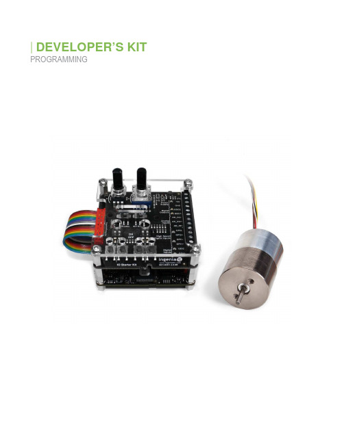
DEVELOPER’S KIT PROGRAMMINGCopyright © 2019 Sensata Technologies, Inc. Rev. 04/11/2023 Installing & Configuring MotionLab1.Head to Ingenia MotionLab and click on the ‘Download ’ button in the software section.2.Run the prompted download and complete the setup as you would any other program.3.While downloading, connect the provided Flash drive to your computer 4.Run MotionLab.5.If your drive has an update, click on ‘New FW Available ’ then click on automatic update in thebox that pops up.6.Select your drive by clicking near the green box above. This will take you to a new screen. If youdo not see your drive:a.Ensure that your drive is connected to the computer.b.Click on scan again.7.Click on ‘Load’ and use the directory to pull up the contents of the flash drive. Load the .xdc filenamed after the actuators part number. If you don’t know the part number, check the engravings on the actuator itself.8.Once loaded, click on ‘Write’ to load the parameters to the drive. At this point your drive is fullyconfigured and ready to use.Move OverviewThis section will discuss the different functions and parameters found within the ‘Move’ window. Entering this window is done by clicking on the top of the main Motionlab window. This action will bring up a new window.Homing: Sets the read value of the shaft location1.Homing method - Chooses the type of homing procedure. I suggest using either NegativeMechanical Limit or Positive Mechanical limit for initial calibration. These methods will push the shaft all the way in, or all the way out respectively.2.Homing offset - This is the value that will be written to the corresponding homing position. In theabove picture, the current position of the shaft will be set to -500 counts.Position: Moves shaft to a designated positionTARGET:1.Target position – sets the shaft to the specified position.a.You can set an accurate desired position with the box to the right of the bar.2.Step size – sets a wanted step size for use with the ‘- step’ and the -+ Step’ buttons. PROFILE:1.Profile velocity – controls speed that shaft attains wanted position.2.Profile acceleration – controls acceleration of shaft towards wanted position.3.Profile deceleration – controls stop speed of shaft when reaching wanted position. LIMITS:1.Minimum absolute position – sets lower limit of shaft position2.Maximum absolute position – sets upper limit of shaft position.THRESHOLDS:1.Position window – sets accepted range of position values relative to target value in which thecontroller will stop trying to correct the shafts current position.2.Position window time – sets the measuring time for the controller to check if position is correct3.Following error window – has a similar concept as the position window. I suggest making thisvalue the same as the position window.4.Following error timeout – sets a measurement time for the shaft position. If the shaft is not in thespecified position for this time an error will be produced.*CONTROL LOOP:1.Proportional gain – sets proportional constant (Kp’) for PID loop.2.Integral gain – sets integral constant (Ki’) for PID loop3.Derivative gain – sets derivative constant (Kd’) for PID loop.4.Integral AW gain – sets integral anti-windup (kii’) constant5.Velocity FF gain – Sets velocity feedforward (Kffv’) constant6.Acceleration FF gain – sets acceleration feedforward (kffa’) constant.7.Integral Limit – puts a limit on the integral gain’s contribution.*This window only controls the position PID loop. It does not affect the force and velocity PID.Velocity: Increases speed that shaft moves toward end of stroke.TARGET:1.Target Velocity – sets desired instantaneous velocity value2.Manual increments – sets a wanted step size for use with the ‘- Target velocity’ and the ‘+ Targetvelocity’ buttons.PROFILER:1.Profile acceleration - Defines the maximum allowed acceleration.2.Profile deceleration - Defines the maximum allowed deceleration.LIMITS:1.Maximum profile velocity - Define the maximal allowed velocity in each direction during a profiledmotion.THRESHOLDS:1.Velocity window – Defines the acceptable window for error. A higher window means a lowertolerance for reaching a specific target velocity.2.Velocity window time- Indicates the configured time (in ms), during which the actual velocitywithin the velocity window is measured. If the actual velocity is within the velocity window for a velocity window time, the target is reached3.Velocity threshold- Indicates the configured zero velocity threshold time. If the actual velocity isabove the velocity threshold longer than velocity threshold time, the motor is seen as moving.4.Velocity threshold time- Indicates the configured zero velocity threshold time. If the actualvelocity is above the velocity threshold longer than velocity threshold time, the motor is moving. **CONTROL LOOP:1.Proportional gain – sets proportional constant (Kp’) for PID loop.2.Integral gain – sets integral constant (Ki’) for PID loop3.Derivative gain – sets derivative constant (Kd’) for PID loop.4.Integral AW gain – sets integral anti-windup (kii’) constant5.Acceleration FF gain – sets acceleration feedforward (kffa’) constant.6.Integral Limit – puts a limit on the integral gain’s contribution.**This only controls the velocity PID loop. The force/position PID is unaffected.Force: Increases Push/Pull force on shaftTARGET:1.Target force – Sets the desired instantaneous torque value.2.Manual increment – Sets incremental torque value for use with ‘- Target force’ and ‘+ Targetforce’ buttons.PROFILER:1.Force Slope – defines slope of force increase towards target force.LIMITS:1.Negative force limit – indicates maximum pulling force2.Positive force limit – indicates maximum pushing forceTHRESHOLDS:1.Force window – Defines the acceptable window for torque/force error. A higher window means alower tolerance for reaching a specific target torque/force.2.Force window time - Indicates the configured time (in ms), during which the actual torque withinthe torque window is measured. If the actual torque is within the torque window for a torquewindow time, the target torque is set as reached.***CONTROL LOOP:1.Proportional gain – defines proportional constant (Kp’) value.2.Integral gain – defines integral constant (Ki’) value3.Cutoff frequency – sets desired cutoff frequency of lowpass filter.***This only controls the force PID loop.Multi-Point: Moves shaft to multiple locations in successionPosition:1.Position box – Sets the desired position2.Capture – Captures the desired position3.Repeat Sequence – Toggles repeat actions after the entire list of positions is reached.4.Pause before repeating – Sets delay before repeat sequence is performedAdditional Position Parameters:1.Profile Parametersa.Profile velocity – controls speed that shaft attains wanted position.b.Profile acceleration – controls acceleration of shaft towards wanted position.c.Profile deceleration – controls stop speed of shaft when reaching wanted position.2.Limit Parametersa.Minimum absolute position – sets lower limit of shaft positionb.Maximum absolute position – sets upper limit of shaft position.3.Threshold Parametersa.Position window – sets accepted range of position values relative to target value in whichthe controller will stop trying to correct the shafts current position.b.Position window time – sets the measuring time for the controller to check if position iscorrectc.Following error window – has a similar concept as the position window. I suggest makingthis value the same as the position window.d.Following error timeout – sets a measurement time for the shaft position. If the shaft isnot in the specified position for this time an error will be produced.Advanced Motion Control:1.Position Loop Parametersa.Proportional gain – sets proportional constant (Kp’) for PID loop.b.Integral gain – sets integral constant (Ki’) for PID loopc.Derivative gain – sets derivative constant (Kd’) for PID loop.d.Integral AW gain – sets integral anti-windup (kii’) constante.Velocity FF gain – Sets velocity feedforward (Kffv’) constantf.Acceleration FF gain – sets acceleration feedforward (kffa’) constant.g.Integral Limit – puts a limit on the integral gain’s contribution. Oscillation: Moves the shaft back and forth between specified boundsInitial Positioning:1.Oscillate around: defines the initial position that the shaft will oscillate around.Oscillation:1.Mode: allows you to choose between a sinusoidal or square oscillation profile.2.Amplitude: defines zero to peak oscillation height. The actual oscillation travel distance will betwice this value3.Frequency: defines the frequency of oscillation.4.Interpolation Period:Additional Position Parameters:1.Profile Parametersa.Profile velocity – controls speed that shaft attains wanted position.b.Profile acceleration – controls acceleration of shaft towards wanted position.c.Profile deceleration – controls stop speed of shaft when reaching wanted position.2.Threshold Parametersa.Position window – sets accepted range of position values relative to target value in whichthe controller will stop trying to correct the shafts current position.b.Position window time – sets the measuring time for the controller to check if position isCorrectAdditional Oscillation Parameters:1.Limit Parametera.Minimum absolute position – sets lower limit of shaft positionb.Maximum absolute position – sets upper limit of shaft position.2.Threshold Parametersa.Following error window – has a similar concept as the position window. I suggest makingthis value the same as the position window.b.Following error timeout – sets a measurement time for the shaft position. If the shaft isnot in the specified position for this time an error will be produced.Advanced Motion Control:1.Position Loop Parametersa.Proportional gain – sets proportional constant (Kp’) for PID loop.b.Integral gain – sets integral constant (Ki’) for PID loopc.Derivative gain – sets derivative constant (Kd’) for PID loop.d.Integral AW gain – sets integral anti-windup (kii’) constante.Velocity FF gain – Sets velocity feedforward (Kffv’) constantf.Acceleration FF gain – sets acceleration feedforward (kffa’) constant.g.Integral Limit – puts a limit on the integral gain’s contribution.Program:This section will display the controller’s ability to run and create macros. Entering this window is done by clicking ‘Program’ on the top of the main Motionlab window. This action will bring up a new window. The image below shows an example of an oscillate function. See Ingenia Knowledge Base for examples of how to execute most move functions. Any other inquiries can be sent to *******************Program Control:1.Write reserved memory2.Load – Brings up explorer to choose a preexisting file.3.Save All – Saves the current macro set up.4.Write All – Writes all macros to the controller5.Set Interruption – Writes interruptions to the controller. Used with Interrupt Designation.6.Run – Runs the selected macro.7.Stop – Force stops all programs.Copyright © 2023 Sensata Technologies, Inc. Rev. 04/11/2023 Sensata Technologies, Inc. (“Sensata”) data sheets are solely intended to assist designers (“Buyers”) who are developing systems thatincorporate Sensata products (also referred to herein as “components”). Buyer understands and agrees that Buyer remains responsiblefor using its independent analysis, evaluation and judgment in designing Buyer’s systems and products. Sensata data sheets have beencreated using standard laboratory conditions and engineering practices. Sensata has not conducted any testing other than thatspecifically described in the published documentation for a particular data sheet. Sensata may make corrections, enhancements,improvements and other changes to its data sheets or components without notice. Buyers are authorized to use Sensata data sheets with the Sensata component(s) identified in each particular data sheet. HOWEVER,NO OTHER LICENSE, EXPRESS OR IMPLIED, BY ESTOPPEL OR OTHERWISE TO ANY OTHER SENSATA INTELLECTUALPROPERTY RIGHT, AND NO LICENSE TO ANY THIRD PARTY TECHNOLOGY OR INTELLECTUAL PROPERTY RIGHT, ISGRANTED HEREIN. SENSATA DATA SHEETS ARE PROVIDED “AS IS”. SENSATA MAKES NO WARRANTIES ORREPRESENTATIONS WITH REGARD TO THE DATA SHEETS OR USE OF THE DATA SHEETS, EXPRESS, IMPLIED ORSTATUTORY, INCLUDING ACCURACY OR COMPLETENESS. SENSATA DISCLAIMS ANY WARRANTY OF TITLE AND ANYIMPLIED WARRANTIES OF MERCHANTABILITY, FITNESS FOR A PARTICULAR PURPOSE, QUIET ENJOYMENT, QUIETPOSSESSION, AND NON-INFRINGEMENT OF ANY THIRD PARTY INTELLECTUAL PROPERTY RIGHTS WITH REGARD TO SENSATA DATA SHEETS OR USE THEREOF.All products are sold subject to Sensata’s terms and conditions of sale supplied at SENSATA ASSUMES NOLIABILITY FOR APPLICATIONS ASSISTANCE OR THE DESIGN OF BUYERS’ PRODUCTS. BUYER ACKNOWLEDGES ANDAGREES THAT IT IS SOLELY RESPONSIBLE FOR COMPLIANCE WITH ALL LEGAL, REGULATORY AND SAFETY-RELATEDREQUIREMENTS CONCERNING ITS PRODUCTS, AND ANY USE OF SENSATA COMPONENTS IN ITS APPLICATIONS,NOTWITHSTANDING ANY APPLICATIONS-RELATED INFORMATION OR SUPPORT THAT MAY BE PROVIDED BY SENSATA. Mailing Address: Sensata Technologies, Inc., 529 Pleasant Street, Attleboro, MA 02703, USA.CONTACT US Americas +1 (760) 597 7042**************************Europe, Middle East & Africa +1 (760) 597 7042support @se Asia Pacific *************************.com China +86 (21) 2306 1500Japan +81 (45) 277 7117Korea +82 (31) 601 2004India +91 (80) 67920890Rest of Asia +603-5566 6001Macro Access:-Lets you choose which macro to edit.-Macro 0 will work on controller startup.Macro Programming:1.Add – Adds the selected item from the dropdown box to the current macro.2.Dropdown – Selects the program function that you want to add to the macro. Requires the ‘Add’button to place.3.Remove All – Deletes all functions from the current macro.4.Save – Saves the current macro.5.Write – Writes the selected macro to the controller6.Copy/Move – Copies or moves the current macro to a macro number of your choosing.7.Current Function Properties – Allows you to edit the highlightedInterrupt Designation:1.Active – Checking the box will allow the interrupt to be written to the controller. You need topress ‘Set Interruptions’ in the Program Control section.2.Source – Selects the type of interrupt you want to use.3.Macro – Designates the macro that will be called when the interrupt is triggered.。
关于MI与CAM数据共享
关于MI与CAM数据共享和效率提升1.前言在很多PCB工厂,通常由MI负责制订料号的工艺流程和拼板方案的选择,而CAM 则根据MI给的指示利用辅助软件(如Genesis2000)制作具体的生产工具。
虽然MI可以通过PT(生产指示)和ERP系统把他处理过的信息反馈到CAM,但是对于CAM来说,由于其所用的软件和平台是一个独立的网络和系统(CAM一般采用UNIX操作系统),与MI使用的系统无法连接,造成两个部门之间的数据共享无法实现,同时也影响了工具制作的效率。
最近FrontLine公司开发的新产品Inplan的出现,使MI和CAM间的数据共享成为了可能。
本文主要论述CAM的Genesis和MI的Inplan间的如何进行数据共享以及如何利用数据共享进行防错校核和提升工具制作效率。
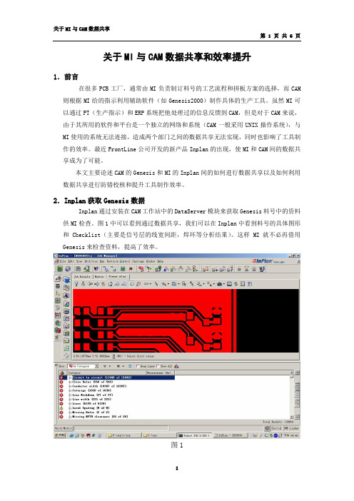
2.Inplan获取Genesis数据Inplan通过安装在CAM工作站中的DataServer模块来获取Genesis料号中的资料供MI检查。
图1中可以看到通过数据共享,我们可以在Inplan中看到料号的具体图形和Checklist(主要是信号层的线宽间距,焊环等分析结果)。
这样MI就不必再借用Genesis来检查资料,提高了效率。
图1由于Inplan如何获取Genesis资料供应商已经提供了解决方案,这里就不再赘述。
而Genesis如何获取Inplan的信息则是空白,所以本文对Genesis如何获取Inplan的数据作详细介绍。
3.Gensis2000获取Inplan中的数据(1)、将Inplan中的数据FTP传输到CAM工作站A、建立GUI传输菜单首先编写一个菜单(见图2),这样MI的员工就能直观地进行数据共享操作,决定数据是否共享给CAM。
图3是程序的部分代码。
图2$mw = MainWindow -> new(-title => 'IntegrationOption...');$mw -> geometry('200x100+200+200');#产生一个主窗口$frmType=$mw->LabFrame(-label=>'TargetDatabase',)-> pack(-pady=>'2',-fill =>'y',-expand => 'y');#定义窗口主题$chkNewErp=$frmType->Checkbutton(-text =>"ToVM",-variable =>\$vm)->grid(-row =>0,-column=>0);#定义发射到”VM”系统选项$chkOldErp=$frmType->Checkbutton(-text =>"ToCAM",-variable =>\$cam)->grid(-row=>0,-column=>1);#定义发射到”CAM”选项$frmBtn=$mw->Frame()->pack(-side =>'bottom');$btnOK=$frmBtn->Button(-text=>'Execute',-width=>'16',-command =>\&execute->pack(-side =>'left');#执行发射任务$btnCancel=$frmBtn->Button(-text=>'Cancel',-width=> '16',-command =>sub{exit} ->pack();图3B、编写程序获取想要的Inplan数据Inplan中的数据很多,我们不可能把所有数据都共享给CAM,而且对于CAM来说只要共享给他与其工具制作相关的数据就可以了,多了反而混乱。
InteGNP快速入门

智能数控套料编程系统InteGNPS初学者快速入门指南一、InteGNPS安装InteGNPS安装说明:★安装AutoCAD,如果AutoCAD已经安装则跳过这一步。
InteGNPS目前支持AutoCAD R12/13/14/2000/2002/2004/2005/2006/2007/2008等各种版本,推荐使用AutoCAD2000以上版本。
★插上加密狗,运行光盘中的integnps-setup.exe文件,按照提示操作即可完成安装。
USB加密狗拔插不用关机,安装软件自带驱动程序,不用额外安装。
支持Windows 98/2000/NT/Me/XP/Vista等各种版本。
★安装完成不用重新启动计算机,直接点击桌面上的InteGNPS快捷方式进入软件:★点击“绘图”菜单中的“装载(或卸载)AutoCAD中的数控菜单”菜单项,按照提示进行操作,AutoCAD 的菜单重新编译完成后菜单中增加了数控的菜单。
如果系统提示装载后不能自动编译数控菜单,可能是AutoCAD版本太低,或者是安装了多个AutoCAD 版本,这时可以在AutoCAD下手动编辑,在AutoCAD命令行下键入menu命令回车,然后选择相应的菜单文件,AutoCAD 2005及以前为版本菜单文件的扩展名为.mnu的文件,AutoCAD 2006及以后版本为.cui文件。
只要保证被装载的菜单文件与重新编译的文件为同一文件,一般都能自动将数控菜单加载到AutoCAD中。
加载后AutoCAD菜单中增加以下菜单项:二、绘图使用AutoCAD绘制零件图需要注意以下几点:★在AutoCAD下按比例(1:1)绘制零件图,单位默认为毫米(根据您选用版本系统所规定的单位绘图,一般为毫米),请参见软件中关于系统中的说明。
★在AutoCAD的DXF或DWG文件中,内轮廓、外轮廓、桥接、划线、冲打、钻孔、铆接等层要分清,请用数控菜单中的修改图层命令,不同的图层显示不同的颜色。
Inplan操作

按钮:
计算后的界面:
培训内容
长短金手指及局部电金(引线不残留)流程讲解一
◘ 长短金手指流程(即不允许引线残留)
流程对应栏位:
[主表面处理+金手指] [是否允许电金引线残留]栏位的勾去掉 [外层正片工艺]
◘ 局部电金流程(且不允许引线残留)
◘ 类型一流程对应栏位(负片流程):
[主表面处理+局部电金] [是否允许电金引线残留]栏位的勾去掉 [周围开窗PAD或开窗PTH孔与电金PAD距离]—大于0.45MM [局部电金位是否有PTH孔]—有 [电金位最小PTH孔钻咀尺寸] [外层负片工艺] [局部电金面向]—TOP面或BOT面
培训内容
干湿膜设置更改讲解
◘ 干湿膜设置
按钮:
计算后的界面:
注意事项: 干湿膜制程及干膜类型只应用于外层图形栏位(不应用于外层图形 2.3.4..),外层图形2.3.4..系统会自动计算显示在流程参数中
培训内容
线路预大参数..更改讲解
备注: 未经过电镀的内层预大规则: 埋盲孔层负片线路预大规则: 外层负片线路预大规则: 外层正片线路预大规则:
[主表面处理+局部电金] [是否允许电金引线残留]栏位的勾去掉 [周围开窗PAD或开窗PTH孔与电金PAD距离]—大于0.45MM [局部电金位是否有PTH孔] [外层正片工艺]
◘ 类型二流程对应栏位(电金位无孔);
培训内容
长短金手指及局部电金(引线不残留)流程讲解二
◘ 局部电金流程(且不允许引线残留)
后需执行[计算流程参数],再刷新流程才能更新当前流程参数)
◘ 输入拼版信息--更改内容
◘ 将[原稿PTH到线路距离]移到[输入基本信息]的Form表中 ◘ 增加<V-CUT方式>及<V-CUT方向>的确认,后续自动添加V-CUT