Delta DVP PLC连线说明
台达DVP-PLC指令表大全
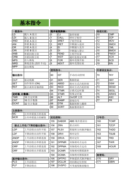
## LD> ## LD< ## LD<> ## LD<= ## LD>= ## AND= ## AND> ## AND< ## AND<> ## AND<= ## AND>= ## OR= ## OR> ## OR< ## OR<> ## OR<= ## OR>=
格雷码: 170 171
GRY GBIN
结束指令:
END
程序结束
其他指令:
NOP
无动作
INV
运算结果反相
P
指针
I
中断插入指针
步进梯形指令:
STL
程序跳至副母线
RET
程序返回主母线
199 DICF
立即变更频率指令
应用指令
较: 定显示:
比较设定输出 区间比较 数据传送 移位传送 反转传送 全部传送 多点传送 数据交换 BIN → BCD 变换 BCD → BIN 变换
台达变频器通讯:
## MODRD
## MODWR ## FWD ## REV ## STOP ## RDST ## RSTEF ## LRC ## CRC ## MODRW ## ASDRW
矩阵: 180 MAND 181 MOR 182 MXOR 183 MXNR 184 MINV 185 MCMP 186 MBRD 187 MBWR 188 MBS 189 MBR 190 MBC
BIN 加法 BIN 减法 BIN 乘法 BIN 除法 BIN 加一 BIN 减一 逻辑与 (AND) 运算 逻辑或 (OR) 运算 逻辑异或 (XOR) 运算 取负数(取 2 的补码)
台达 说明书07-通讯联机模式
在进行通讯联机操作前请先确定PC与PLC已完成硬件上联机工作(PC的RS232通讯口及PLC通讯口之间已建立联机)。
WPLSoft在通讯功能上提供更多样的操控工具(例:窗口装置监控、缓存器列表传输、速度设定……等),方便使用者可以利用WPLSoft来进行编辑、监控及测试等相关设计工作。
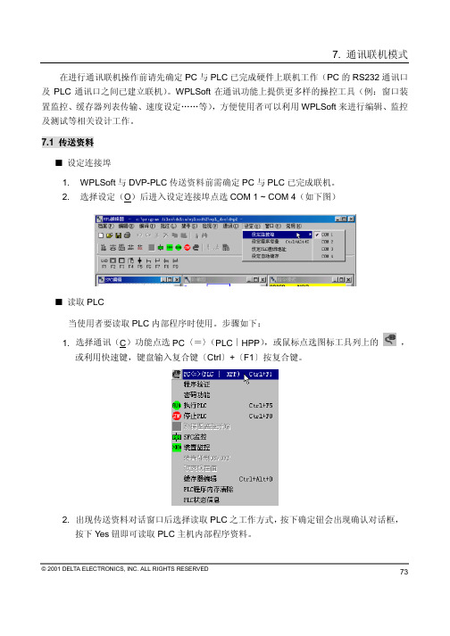
7.1 传送资料设定连接埠1. WPLSoft与DVP-PLC传送资料前需确定PC与PLC已完成联机。
2. 选择设定(O)后进入设定连接埠点选COM 1 ~ COM 4(如下图)读取PLC当使用者要读取PLC内部程序时使用。
步骤如下:1. 选择通讯(C)功能点选PC〈=〉(PLC∣HPP),或鼠标点选图标工具列上的,或利用快速键,键盘输入复合键〔Ctrl〕+〔F1〕按复合键。
2. 出现传送资料对话窗口后选择读取PLC之工作方式,按下确定钮会出现确认对话框,按下Yes钮即可读取PLC主机内部程序资料。
© 2001 DELTA ELECTRONICS, INC. ALL RIGHTS RESERVED 7374写入PLC1. 使用者执行WPLSoft自磁盘读取一项目或由阶梯图编辑、指令编辑设计一个新的PLC程序,要传送至DVP-PLC主机时,选择通讯(C)功能点选PC〈=〉(PLC∣HPP),或鼠标点选图标工具列上的,或利用快速键,键盘输入复合键〔Ctrl〕+〔F1〕。
2. 于传送资料(*注一)对话窗口选择写入PLC工作方式;WPL提供2种传送方式:全部传送与部分传送。
全部传送:将WPLSoft目前程序区内存全部写入DVP-PLC主机(如下图)。
部分传送:由使用者设定欲传送之程序区内存的起始及结束地址,将此部分程序写入DVP-PLC主机(如下图)。
© 2001 DELTA ELECTRONICS, INC. ALL RIGHTS RESERVED© 2001 DELTA ELECTRONICS, INC. ALL RIGHTS RESERVED75*注一:在执行写入功能前,必须注意PLC 必须在停止(STOP )的状态,若PLC 为运行(RUN )状态,则WPLSoft 会发出PLC 执行中禁止写入的警告讯息(如下图)。
DELTA DVPPS01 DVPPS02 说明书
5011619800-PC00200412-29DVPPS01 DVPPS02POWER OUTPUT MODULE1注 意 事 項本使用說明書僅提供電氣規格、功能規格、安裝配線、故障排除部份說明。
本機為開放型(OPEN TYPE)機殼,因此使用者使用本機時,必須將之安裝於具防塵、防潮及免於電擊/衝擊意外之外殼配線箱內。
另必須具備保護措施 (如: 特殊之工具或鑰匙才可打開) 防止非維護人員操作或意外衝擊本體,造成危險及損壞。
交流輸入電源不可連接於輸入/出信號端,否則可能造成嚴重損壞,請在上電之前再次確認電源配線。
本體上之接地端子務必正確的接地,可提高產品抗雜訊能力。
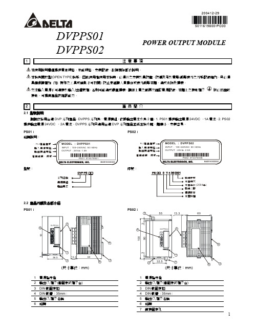
2產 品 簡 介2.1 型號說明謝謝您採用台達DVP 系列產品。
DVPPS 系列為一電源模組,依據輸出電流分為2種。
1. PS01提供輸出電源24VDC ,1A 電流。
2. PS02提供輸出電源24VDC ,2A 電流。
DVPPS 系列只適用台達DVP 系列產品並與主機分離,體積小,安裝容易。
PS01: 銘牌說明:P L C 產品型號輸入電源規格輸出模組規格管制條碼、序PS02:P L C 產品型號輸入電源規輸出模組規管制條碼、序型號:系列名稱電源模組輸出電流序號:製造序號生產週次生產年份年 (2004)製造工廠標準版本生產機種2.2 產品外觀及各部介紹 PS01:(尺寸單位:mm)1 電源指示燈1電源指示燈2 輸出/入端子(著固定式端子台) 2輸出/入端子(著固定式端子台)3 DIN 軌固定扣 3DIN 軌固定扣4 DIN 軌糟﹝35mm ﹞ 4DIN 軌糟﹝35mm ﹞5 輸出/入端子名稱 5輸出/入端子名稱6 銘牌 6銘牌7直接固定孔3功 能 / 電 氣 規 格4安 裝 及 配 線4.1盤內安裝及配線 ■ DIN 鋁軌之安裝方法適合35mm 之DIN 鋁軌,DVPPS 系列欲掛於鋁軌時,先將下方之固定塑膠片壓入,再將DVPPS 系列由上方掛上再往下壓即可。
台达DVP系列可编程控制器使用说明书
目 录 1. 产品简介........................................................................1
1.1. 型号说明及外围装置....................................................... 1 1.2. 产品外观及各部介绍....................................................... 3
2. 功能规格一览表 .............................................................8 3. 特殊组件......................................................................10
DELTA ELECTRONICS, INC.
MADE IN TAIWAN
型号说明
DVP
系列名稱 點數 (輸入+輸出) 主機/擴展機區分 E : 主機 X : 擴展機 機型區分 S : 標準功能型主機 X : 混合功能型主機 (A/D, D/A功能) M : 輸入點擴展機 N : 輸出點擴展機 P : 輸入/輸出點擴展機
0 T 0 20 004
製造序號 生產週次 生產年份 ( 2000 年 ) 製造工廠 ( 桃園廠 ) 版掌上型程序书写器 ◎ DPLSoft(DOS 版本)阶梯图编辑程序、WPLSoft(Windows 版本)阶梯图编辑程序 ◎ DVPACAB115 连接线(HPP Ù PLC/1.5 公尺,DVPHPP01 内含此连接线) ◎ DVPACAB215 连接线(PC Ù PLC/1.5 公尺) ◎ DVPACAB315 连接线(HPP Ù PC,1.5 公尺) ◎ DVPACAB403 连接线(主机Ù扩展机 或 扩展机Ù扩展机 I/O 信号延长线,30 公分) ◎ DVPAADP01(HPP 专用电源,内含 DVPACAB315)
台达 DVP 系列可编程控制器 安装说明
ݭʔкΑਕʔᖳಱ΄ะ!!Ξበଠטጡ!щ྅ᄲځ!ڦຍְี!3 本使用说明书仅提供电气规格、功能规格、安装配线、故障排除及周边装置部份说明,详细说明请见DVP-PLC应用技术手册【程序篇】。
选购外围装置详细说明请见该产品随机手册或DVP-PLC 应用技术手册【特殊单元篇】。
3 本机为开放型 (OPEN TYPE) 机壳,因此使用者使用本机时,必须将之安装于具防尘、防潮及免于电击/冲击意外的外壳配线箱内。
另必须具备保护措施 (如: 特殊的工具或钥匙才可打开) 防止非维护人员操作或意外冲击本体,造成危险及损坏。
3 交流输入电源不可连接于输入/出信号端,否则将造成严重损坏。
本机为直流电源供应,请在上电之前再次确认电源配线。
请勿在上电时触摸任何端子。
本体上的接地端子务必正确的接地,可提高产品抗噪声能力。
X யݡᖎ̬1.1 型号说明及外围装置谢谢您采用台达DVP 系列可编程控制器。
SV 为28点(16输入点 + 12输出点)PLC 主机,提供丰富的指令集,并具有16K Steps 的程序内存,可连接SS/SA/SX/SC/SV 全系列扩充机,包含数字输入/输出(最大输入/输出扩充点数可达512点)、模拟模块(A/D 、D/A 转换及温度单元)及新型高速扩充机等各类机型。
四组高速(200KHz )脉冲输出、新增两轴插补指令,可满足各种应用场合,并且体积小,安装容易。
铭牌说明台达 PLC型号序号系列名称点数 (16 SV 系列T :晶体管直流电源输入R :继电器制造序号生产年份年 ( 2006 )生产周次制造工厂桃园厂 ( )版本序号生产机种1.2 产品外观及各部介绍1电源、运行、电池低电压及错误指示灯2 COM1 (RS-232) 通讯接收 (Rx) 指示灯3 COM2 (RS-485) 通讯传送 (Tx) 指示灯 4输出/入点指示灯5 RUN/STOP 开关6 VR0:M1178启动/D1178对应值7 VR1:M1179启动/D1179对应值 8输出/入端子9 COM1 (RS-232) 程序输出/入通讯口 10 DIN 轨固定扣 11扩充机定位孔12 扩充机连接口 13 DIN 轨糟 (35mm) 14 扩充机固定扣15 COM2 (RS-485) 通讯口 (Master/Slave) 16 电源输入口17 3 P 脱落式端子 (标准附件)18 电源输入连接线 (标准附件) 19 新型高速扩充机连接口 20 铭牌尺寸单位:mm21 直接固定孔Y Αਕఢॾ项目规格备注演算控制方式 内存程序,往返式来回扫描方式 - 输入/输出控制方式 结束再生方式 (当执行至END 指令) 输入/出有立即刷新指令 演算处理速度 基本指令 (最小0.24 us) 应用指令 程序语言 指令 + 阶梯图 + SFC 含有步进指令程序容量 15872 STEPS SRAM+充电式电池+Flash 指令种类 基本顺序指令32个 (含步进阶梯指令) 应用指令193种 X 外部输入继电器 X0 ~ X377, 8进制编码, 256点 对应至外部输入点Y 外部输出继电器 Y0 ~ Y377, 8进制编码, 256点 合计512点对应至外部输出点一般用 M0 ~ M499, 500点(*2)M500 ~ M999, 500点(*3)停电保持用 M2000 ~ M4095, 2096点(*3)M 辅助继电器 特殊用 M1000 ~ M1999, 1000点(部份为停电保持)合计4,096点 接点可于程序内做On/OffT0 ~ T199, 200点(*2)T192 ~ T199为子程序用100ms T250 ~ T255, 6点累计型 (*4)T200 ~ T239, 40点 (*2)10msT240 ~ T245, 6点累计型(*4)T 定时器 1ms T246 ~ T249, 4点累计型 (*4)合计256点 TMR 指令所指定的定时器,若计时到达则此同编号T 的接点将会On 。
Delta DVP系列PLC模块说明书

………………………………………………………………… ENGLISH …………………………………………………………………Thank you for choosing the Delta DVP series PLC. Four channels on DVP04DA-H3 are able to receive four pieces of 16-bit digital data from a CPU module, and convert them into analog signals (voltages or currents). Users can read data from the module or write data into the module by means of the instruction FROM/TO in a DVP-EH2 series PLC. There are 49 control registers in the module, and they are 16-bit registers. Whether the output signals are voltage outputs or current outputs depends on the wiring. The voltage output range is ±10VDC. (The resolution is 312.5μV.) The current output range is 0~20 mA. (The resolution is 0.625μA).a Please read this instruction sheet carefully before using the product.a Switch off the power supply before wiring. Please do not touch the internal circuit untilthe power supply has been switched off for one minute.a DVP04DA-H3 is an OPEN-TYPE device. It should be installed in a control cabinetfree of airborne dust, humidity, electric shock and vibration. To prevent thenon-maintenance staff from operating the product, or to prevent an accident from damaging the product, the control cabinet should be equipped with a safeguard. For example, the control cabinet is unlocked with a special tool or key.a DO NOT connect the input AC power supply to any of I/O terminals; otherwiseserious damage may occur. Check all the wiring again before switching on the power supply. Do NOT touch any terminals when the power supply is switched on.a Make sure that the ground terminal is correctly grounded in order to preventelectromagnetic interference.Product Profile & DimensionsUnit: mm1. Groove (35 mm) 6.Terminals2. Connector 7.Mounting hole3. Model name 8.Arrangement of I/O terminals4. POWER, ERROR, and D/A LED indicators9.Connector5. Mounting holeI/O Terminal LayoutExternal Wiringa reIt is*1. Please isolate the analog output from other power cables.*2. If the ripple is large for the input terminal of the load and results in the noise interference with the wiring, please connect the module to the capacitor having a capacitance within the range between 0.1μF and 0.47μF with a working voltage of 25V.*3. Please connect the terminal on a CPU module and the terminal on DVP04DA-H3 toa system ground, and then ground the system ground, or connect it to a distribution box.SpecificationsDigital-to-analog module Voltage output Current outputSupply voltage 24VDC (20.4VDC~28.8VDC) (-15%~+20%)Number of channels 4 channelsAnalog output range -10V~+10V 0~20mA Digital data range -32,000~+32,000 0~32,000 Resolution 16 bits (312.5μV) 15 bits (0.625μA)Input impedance 0.5 Ω or belowOverall accuracy 25°C/77°F: ±0.5% of the input within the range0~55°C/32~131°F: ±1% of the input within the rangeResponse time 1msMaximum outputcurrent10mA -Permissible loadimpedance-0~500ΩData format Two’s complement (16-bit data)Isolation The internal circuit is isolated from the analog outputs by an optocoupler, and the analog channels are not isolated from one another.Protection The voltage output is equipped with the short circuit protection. However, users must notice that a long-term short circuit will damage the internal circuit. The current output can be an open circuit.Digital-to-analog module Voltage output Current outputCommunication mode (RS-485) ASCII/RTU modeCommunication speed: 4,800/9,600/19,200/38,400/57,600/115,200 bpsASCII data: 7-bit, even bit, 1 stop bit (7, E, 1)RTU data: 8-bit, even bit, 1 stop bit (8, E, 1)When DVP04DA-H3 is connected to a CPU module, the RS-485 communication can not be used.Connection with a DVP-PLC CPU The modules are numbered according to their distances from the CPU module. The numbers start from 0 to 7. Eight modules at most can be connected, and they do not occupy digital inputs/outputs.Other SpecificationsPower specificationsRated maximum power consumption 24VDC (20.4VDC~28.8VDC) (-15% ~ +20%); 4.5W An external power supply supplies the DC voltage.Environment specificationsOperation/Storage Operation: 0°C~55°C (temperature); 50~95% (humidity); pollution degree 2Storage: -25°C~ 70°C (temperature), 5~95% (humidity)Vibration/Shock resistance International standards IEC 61131-2, IEC 68-2-6 (TEST Fc)/IEC 61131-2 & IEC 68-2-27 (TEST Ea)Control RegisterCR# ParameteraddressAttribute Register name Description#0 H’5032 O R Model The model is defined by the system. The modelof DVP04DA-H3 is H’6408.Users can read the model from the register by means of the program.b15 ~ b12b11 ~ b8B7 ~ b4 b3 ~ b0 CH4 CH3 CH2 CH1#1 H’5033 O R/W Output modes Mode 0000: Voltage output (-10 V~+10V) Mode 0001: Voltage output (-5 V~+5 V) Mode 0010: Voltage output (1 V~+5 V) Mode 0011: Current output (4 mA~+20 mA) Mode 0100: Current output (0 mA~+20 mA) Mode 1111: The channel is disabled.CR#1: The value in the register represents the working modes of the four channels. If CH1 is in mode 0 (b3~b0=0000), CH2 is in mode 1 (b7~b4=0001), CH3 is in mode 2 (b11~b8=0010), and CH4 is in mode 3 (b15~b12=0011), the value in CR#1 is H’3210. The default value in the register is H’0000.#2 H’5038 X R/W Value sent by CH1#3 H’5039 X R/W Value sent by CH2#4 H’503A X R/W Value sent by CH3#5 H’503B X R/W Value sent byCH4Values sent by CH1~CH4 are stored in theseregisters.Range: K-32000~K32000Default: K0Unit: LSB#6 H’5044 O R/W Offset used for calibrating the signal sent by CH1#7 H’5045 O R/W Offset used for calibrating the signal sent by CH2#8 H’5046 O R/W Offset used for calibrating the signal sent by CH3#9 H’5047 O R/W Offset used forcalibrating thesignal sent byCH4Users can store the offsets in these registers.Default: K0Unit: LSB#12 H’504A O R/W Gain used for calibrating the signal sent by CH1#13 H’504B O R/W Gain used for calibrating the signal sent by CH2#14 H’504C O R/W Gain used for calibrating the signal sent by CH3#15 H’504D O R/W Gain used forcalibrating thesignal sent byCH4Users can store the gains in these registers.Default: K16,000Unit: LSB#30 H’5050 X R Errorstate The error state is stored in this register. Please refer to error message table below.#31 H’5051 O R/W CommunicationaddressThe RS-485 communication address is stored inthis register. The setting range is 01 ~ 254. Thedefault value is K1.#32 H’5052 O R/W CommunicationspeedCommunication speed:4,800/9,600/19,200/38,400/57,600/115,200 bpsASCII data: 7-bit, even bit, 1 stop bit (7, E, 1)RTU data: 8-bit, even bit, 1 stop bit (8, E, 1)Default: H’0002b0: 4,800 bps; b1: 9,600 bps (default)b2: 19,200 bps; b3: 38,400 bpsb4: 57,600 bps; b5: 115,200 bps (bits/second)b6~b13: Reservedb14: The high byte of the CRC checksum isinterchanged with the low byte of the CRCchecksum. (Only the RTU mode supportsthe interchange.)b15: Switch between the ASCII mode and theRTU mode (0: ASCII mode (default))b15 ~ b12b11~b9b8~b6 b5~b3 b2~b0Reserved CH4 CH3 CH2 CH1#33 H’5053 O R/W Restoring allthe settingvalues to thefactory settingThe default value is H’0000. Take CH1 forexample. If the value of b2 is 1, all the settingvalues are restored to the factory setting.#34 H’5054 O R FirmwareversionThe current version of the firmware isrepresented by a hexadecimal number. Forexample, if the current version of the firmware is1.0A, it is represented by H’010A.#35 ~ #48 For system use onlyThe definitions of the symbols:O indicates that the register is a latched register. (Data needs to be written into the register through the RS-485 communication.) X indicates that the register is a non-latched register. R indicates that the data can be read from the register by means of the instruction FROM or through the RS-485 communication.W indicates that the data can be written into the register by means of the instruction TO or through the RS-485 communication.Least significant bit (LSB): 1. Voltage output: 1LSB=10 V/32,000=0.3125 mV2. Current output: 1 LSB=20 mA/32,000=0.625 μA※ Error state tableError state Value b15 ~ b8 b7b6b5b4 b3 b2 b1 b0The power supply is abnormal. K1(H’1) 0000 0 0 0 1Hardware failure (GPIO) K2(H’2) 0000 0 0 1 0Offset/Gain error K8 (H’8) Reserved0000 1 0 0 0Note: Every error state depends on the value of a corresponding bit. There may more than two error states at the same time. If the value of a bit is 0, there is no error. If the value of a bit is 1, there is an error.CR#0~CR#34: Their corresponding parameter addresses are H’5032~H’5054. Users can read/write data through the RS-485 communication. When users use the RS-485 communication, they must separate the module from the CPU module.1. They support the communication speed 4,800/9,600/19,200/38,400/57,600/115,200bps.2. Users can use the Modbus ASCII/RTU mode.ASCII data: 7-bit, even bit, 1 stop bit (7, E, 1)RTU data: 8-bit, even bit, 1 stop bit (8, E, 1)3. Function code:H’03: Reading the data from the registerH’06: Writing the data into the registerH’10: Writing the data into several registers.4. If the register is a latched register, users need to write the data into the registerthrough the RS-485 communication. If users write the data into the latched register by means of the instruction TO/DTO, the data is not retained when there is power failure.Adjust Conversion CurveUsers can adjust the conversion curves according to the practical application by changing the offset values (stored in CR#6~CR#9) and the gain values (stored inCR#12~CR#15).Gain: The corresponding voltage/current input value when the digital output value = 16,000.Offset: The corresponding voltage/current input value when the digital output value = 0.y Equation for voltage output Mode0: 0.3125mV = 20V/64,000()()⎟⎠⎞⎜⎝⎛×⎥⎦⎤⎢⎣⎡+−×=32000)(1016000V Offset Offset Gain X V YY=Voltage output, X=Digital inputy Equation for current output Mode1: 0.625μA = 20mA/32,000()()⎟⎠⎞⎜⎝⎛×⎥⎦⎤⎢⎣⎡+−×=32000)(2016000mA Offset Offset Gain X mA YY=Current output, X=Digital inputy Equation for current output Mode2: 0.5μA = 16mA/32,000Adopt the equation of current output mode 1, substitute Gain for 19,200(12mA) andOffset for 6,400(4mA)()()⎟⎠⎞⎜⎝⎛×⎥⎦⎤⎢⎣⎡+−×=32000)(20640016000640019200mA X mA YY=Current output, X=Digital inputy Mode 0:y Mode 1:Mode 0 (CR#1) -10V~+10V; Gain=5V (16,000),Offset = 0V (0) Mode 1 (CR#1) -5V~+5V; Gain=2.5V (16,000),Offset = 0V (0) Range of digital values-32,000~+32,000y Mode 2:y Mode 3:Volt ag e ou tp utC urren t ou tp uty Mode 4:Mode 2 (CR#1) 1V~+5V; Gain=3V; Offset=1VMode 3 (CR#1) +4mA~+20mA; Gain=12mA (19,200); Offset=4mA (6,400) Mode 4 (CR#1) 0mA~+20mA; Gain=10mA (16,000); Offset=0V (0) Range of digital values 0~+32,000……………………………………………………………… 繁體中文 …………………………………………………………………………感謝您採用台達DVP系列產品。
DELTA DVP-SS可编程序控制器 说明书
8. 扩展连接口 9. 扩展固定扣 10. DIN 轨糟﹝35mm﹞ 11. RS-485 通讯口 12. 扩展固定槽 13. 电源输入口 14. RUN / STOP 开关
2.3. 机种型号
◎ 标准功能型主机 MPU
机种
电源
输入/输出
输入单元
点数
形式
规格 输出单元
点数 形式
DVP14SS11R2
8
外围装置
◎ DVP-HPP 掌上型程序书写器 ◎ WPLSoft(Windows 版本)梯形图编辑程序软件 ◎ DVPACAB115 连接线(HPP PLC/1.5 公尺,DVPHPP 内含此连接线) ◎ DVPACAB215 连接线(PC PLC/1.5 公尺) ◎ DVPACAB230 连接线(PC PLC/3 公尺),DVPACAB2A30 连接线(PC ◎ DVPAADP01(HPP 专用电源,内含 DVPACAB315)
100~240VAC (50/60Hz)
输出电压:24VDC 最大输出电流:1A
外形参考 外形参考
DVPPS02
100~240VAC (50/60Hz)
输出电压:24VDC 最大输出电流:2A
3
功能規格
3.1. 功能规格
项
目
演算控制方式
输入/输出控制方式
演算处理速度
程
序
语
言
程
序
容
量
指
令
种
类
步进继电器 初 始 步 进 点
铭牌说明
台 達P L C產 品 型 號
輸入電源規格
輸出點模塊規格
管制條碼及序號
程序版本
V4.9
24Vdc 5.5W 0.3A 30Vdc RES LOAD
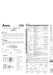
DELTA DVP04AD-H 模拟输入模块 安装说明
平均功能
有(CR#2~CR#5 可设定,范围 K1~K20)
自我诊断功能
上下极限侦测 / 通道
通信模式(RS-485)
包含 ASCII/RTU 模式,通讯速率可选(4800/9600/19200/38400/57600/115200),ASCII 模式数据格式固定为 7Bit、偶位、1 stop bit ( 7 E 1),RTU 模式数据格式固定为 8Bit、 偶位、1 stop bit ( 8 E 1)。当与 PLC 主机串接时,RS-485 通讯无法使用。
电压输入时:可设定范围 K-3200 ~K16000。 电流输入时:可设定范围 K-3200 ~K10400。
#27 H 401B ○ R/W CH4 微调 GAIN 值
#28~ #29
保留。
#30 H 401E ╳ R 错误状态
储存所有错误状态的数据寄存器,详细内容请参照错误信息表。
#31 H 401F ○ R/W 通讯地址设定
DVP04AD-H 模拟信号输入模块可经由 RS-485 通讯来更新韧体版本。
使用者可经由配线选择电压输入或电流输入。电压输入范围 ±10V DC (分辨率为 1.25 mV)。电流输入范围 ± 20 mA (分辨率为 5 μA)。
铭牌说明
P L C產 品 型 號 輸入電源規格 模擬輸 出入模塊規格
交流输入电源不可连接于输入/出信号端,否则可能造成严重的损坏,因此请在上电之前再次确认电源配线。
请勿在上电时触摸任何端子。输入电源切断后,一分钟之内,请勿触摸内部电路。
本体上之接地端子
务必正确的接地,可提高产品抗噪声能力。
2
產品簡介
2.1 型号说明及外围装置
谢谢您采用台达 DVP 系列产品。DVP04AD-H 模拟信号输入模块可接受外部 4 点模拟信号输入(电压或电流皆 可),将之转换成 14 位之数字信号。透过 DVP-EH 系列主机程序以指令 FROM / TO 来读写模块内之数据,模 块内具有 49 个 CR(Control Register)寄存器,每个寄存器有 16 bits。
- 1、下载文档前请自行甄别文档内容的完整性,平台不提供额外的编辑、内容补充、找答案等附加服务。
- 2、"仅部分预览"的文档,不可在线预览部分如存在完整性等问题,可反馈申请退款(可完整预览的文档不适用该条件!)。
- 3、如文档侵犯您的权益,请联系客服反馈,我们会尽快为您处理(人工客服工作时间:9:00-18:30)。
系列人机与各厂牌连线说明
Delta DVP PLC
人机默认值
通讯速率:9600, 7, Even, 1
控制器站号:1
控制区/状态区:D0 / D10
控制器接线的说明
a. RS-232(DOP-A/AE/AS, DOP-B系列适用)
b. RS-485(DOP-A/AE系列适用)
c. RS-485(DOP-AS57系列适用)
系列人机与各厂牌连线说明d. RS-485(DOP-AS35/AS38系列适用)
e. RS-485(DOP-B系列适用)
控制器Read/Write 地址的定义
a. 寄存器
符号格式
读写地址范围数据长度注寄存器种类
Word No.(n)
X_Data X n X0 – X360 Word 8进位, 1
Y_Data Y n Y0 – Y360 Word 8进位, 1
符号格式
读写地址范围数据长度注寄存器种类
Word No.(n)
M_Data M n M0 – M1520, M1536 – M4080Word 1
S_Data S n S0 – S1008 Word 1
T_Register T n T0 – T255 Word
C_Register C n C0 – C199 Word
D_Register D n D0 – D9999 Word
HC_Register C n C200 – C255 Word
系列人机与各厂牌连线说明
b. 接点
符号格式
接点种类
读写地址范围注
Bits No.(b)
X_Data X b X0 – X377
Y_Data Y b Y0 – Y377
M_Data M b M0 – M4080
S_Data S b S0 – S1023
T_Coil T b T0 – T255
C_Coil C b C0 – C255
注1元件地址必须是16的倍数。