M50026ERDK-R中文资料
PM50RSK060资料

MITSUBISHI INTELLIGENT POWER MODULES
PM50RSK060
FLAT-BASE TYPE INSULATED PACKAGE
A B J N U
123 4
N N
5678 9 11 13 15 17 19
10 12
14 16 18
D
Applications: Inverters UPS Motion/Servo Control Power Supplies Ordering Information: Example: Select the complete part number from the table below -i.e. PM50RSK060 is a 600V, 50 Ampere Intelligent Power Module.
Sep.1998
元器件交易网
MITSUBISHI INTELLIGENT POWER MODULES
PM50RSK060
FLAT-BASE TYPE INSULATED PACKAGE Electrical and Mechanical Characteristics, Tj = 25°C unless otherwise specified
Control Sector
Supply Voltage (Applied between VUP1-VUPC, VVP1-VVPC, VWP1-VWPC, VN1-VNC) Input Voltage (Applied between UP-VUPC, VP-VVPC, WP-VWPC, UN · VN · WN-VNC) Fault Output Supply Voltage (Applied between UFO-VUPC, VFO-VVPC, WFO-VWPC, FO-VNC) Fault Output Current (Sink Current of UFO, VFO, WFO and FO Terminal) VD VCIN VFO IFO 20 20 20 20 Volts Volts Volts mA
R550 R600 R650 R750 使用说明书

Imprint:Instruction Manual R550 / R600 / R650 / R750© ROTHENBERGER Werkzeuge GmbH, 2003We reserve the right to revise product specifications at any time without notice. Editorial/Typeset/DTP: ROTHENBERGER Werkzeuge GmbH • D-65779 Kelkheim Edition 09 / 2003Printed in the F.R. of GermanyPlease read the Instruction Manual carefully first! • Don't throw it away! If damages are caused by operating errors or misuse the warranty expires!Contents PageComments 121. Safety1.1 Use in accordance with the regulations 121.2 Applied safety symbols and their meaning 121.3 Indication to the safety of man and machine 122. Technical Data 143. Function of the Unit 1414Description3.1Design/summery14Equipment3.1.1description14Functional3.1.2Operation153.23.3 Removal of pipe blockages 163.4 Retrieval of the spirals from the pipe 16Toolchanging 163.53.6 Working using 8 mm or 10 mm spirals 1717Shut-down3.74. Troubleshooting 17Repair 185. Serviceand5.1Service 1818Repair5.2Maintenance,Recondition,5.2.1 Changing of the clamp-mounting system 186. Disposal 197. CE-Statement of Conformity 198. Warranty s. appendix 11. Safety Comments1.1Use in accordance with the regulationsThe drain cleaning machines are only to be used for pipe cleaning of the following pipe-diameters:R550 20-100mm / R600-650 20-150mm / R750 20-200mmThe drain cleaning machines may not be operated under load longer than 15 minutes.1.2Applied safety symbols and their meaningFailure to comply with these safety marks (WARNING) means danger to life and health ofindividuals.Failure to comply with these safety marks (CAUTION) means a possibly dangerous situation whichmay result in injuries or damage to property.This symbol (NOTE) points to important advice for the proper handling of the machine. Failure tocomply with these notes may cause malfunction of themachine or interference to the environment.1.3 Indication to the safety of man and machineKeep your working area in an orderly state. Disorder can cause accidents!Bear ambient factors of influences in mind. Do not expose electrical power tools to rain.Do not use electrical power tools in damp or wet environments. Ensure good lighting. Do not useelectrical power tools in the proximity of combustible liquids or gasesProtect yourself from electric shock. Avoid bodily contact with earthed parts, e.g. pipes,radiators, cookers, refrigerators!Keep children away. Do not allow other persons to touch the tool or flex. Keep other personsaway from your working area.Store your tools safely. Unused tools should be stored in a dry and locked room and in such away that they are not accessible to children.Do not overload your tool. You will work better and more safely if you stay within thespecified capacity range.Use the proper tool. Do not use tools or adapter devices which are too weak for heavy work.Do not use tools for purposes and work for which they were not intended, e.g. do not usehandheld circular saws to cut trees or branches.Wear suitable work clothing. Do not wear wide clothing or jewellery, both of which can becaught by moving parts. When working outdoors, rubber gloves and anti-slip shoes are advisable.If your hair is long, wear a hairnet.Wear protective goggles. Use an oxygen mask for work where a dusty atmosphere is likely tobe generated.Do not misuse the flex. Do not carry the tool by the flex and do not use the flex to pull the plug out of the socket outlet. Protect the flex from heat, oil and sharp edges.Secure the work piece. Use clamping mechanisms or a vise in order to secure the work piece. In that way, the work piece is held more securely than when held by your hand and allows you instead to operate the machine using both hands.Do not overextend your standing area. Avoid abnormal postures. Ensure that you are standing safely and have proper balance at all times.Take care of your tools meticulously. Keep your tools sharp and clean to enable you to workwell and safely. Adhere to the maintenance instructions and the instructions for tool changing. Check the plug and the flex regularly and, if they are damaged, have them upgraded by an approved professional. Check the extension cable regularly and replace it if damaged. Keep the handgrips dry and free from oil and grease.Pull out the mains plug when not using the tool, before performing maintenance work and when changing a part of the tool, such as e.g. saw blade, drill and machine tools of all kinds.Do not leave a tool wrench inserted. Before switching on the power, check that the wrenches and setting tools are removed.Avoid starting the tool unintentionally. Do not carry tools which are connected to thepower mains while holding your finger on the switch. When plugging the tool into the power mains, make sure that the switch is off.Extension cables outdoors. When working outdoors, only use extension cables which areapproved for this purpose and correspondingly labelledBe at all times attentive. Monitor your work. Proceed rationally. Do not use the tool if you are not able to concentrateCheck your appliance for damage. Before using the tool any further, check carefully that the protective mechanisms and any slightly damaged parts are functioning perfectly and in line with the regulations and with their intended purpose. Check that the moving parts are functioning properly, that they are not stuck and that no parts are damaged. All parts must be mounted properly and all conditions fulfilled in order to ensure the sound operation of the appliance. Where not otherwise stated in the operating manuals, damaged protective devices and parts should be properly repaired by a customer service workshop or replaced by same. Damaged switches must be replaced by a customer service workshop. Do not use tools on which the power switch cannot be switched on and off .Caution. For your own safety, only use accessories and auxiliary devices which are specified foruse in the operating manual or recommended or specified by the tool manufacturer. The use of tools or accessories other than those recommended in the operating manual or in the catalogue can entail a danger of personal injury to you.Have your electrical power tools repaired by a skilled electrical specialist. ROTHENBERGER electrical power tools are in accordance with the relevant safety regulations. Repairs are only permitted to be performed by a skilled electrical specialist. Otherwise, accidents can happen to the user.Data2. TechnicalR550 R600 Saniclean R650 Powerclean R750 Motor rating 250 Watt 400 Watt 800 Watt 900 Watt07.2655 07.2665 07.2670 07.2910Voltage 230 V; 50 Hz 230 V; 50 Hz 220-240 V; 50 Hz 220-240 V; 50 Hz07.291107.2863 07.2869110/115V; 50Hz 110/115V; 50Hz 110/115V; 50Hz Operating speed 575 U/min 460 U/min 620 U/min 460 U/minWeight 15 kg 20,9 kg 22,8 kg 29,5 kgSpirals Ø16 Ø16; Ø22 Ø16; Ø22 Ø16; Ø22; Ø32(Ø8;Ø 10with (Ø8;Ø 10with (Ø8;Ø 10with (Ø8;Ø 10withaccessories) accessories) accessories) accessories) max. working length 40m 60m 65m 80mdiameterPipeRange Ø20-Ø100mm Ø20-Ø150mm Ø20-Ø150mm Ø20-Ø200mmNoise level 75 dB (A) 75 dB (A) 80 dB (A) 80 dB (A)I I I IclassProtectionUnitthe3. Functionof3.1 Design/Description3.1.1 Equipment summeryEquipment summary/Controls (>see fold-out page)Abb.1 : A = Hand lever B = Main switch C = SpiralD = ToolE = Holder for spiralF = Power cableAbb.2 : (Access.) G = Spirals H = Guide hose I = Spray for spiralK = safety gloves L = Tools3.1.2 FunctionaldescriptionIn the model R550 / R600 / R650 / R750, you have purchased a highly efficient, portable and easy-to-usedrain-cleaning machine.The machine functions on the "Sectional Cable" principle, i.e., only as many spirals as are necessary arecoupled together.This makes it possible to design the machine with a speed of rotation which permits efficient pipe cleaning witha diverse range of tools.The machine is electrically driven. The power of the motor is transmitted to the spirals via the clamp-mountingsystem by exerting pressure on the hand-lever.If the hand-lever is an inoperative position, you can push up the lockpin and the hand-lever can be used as antransport handle. If you push down the hand-lever , the locking is released.By model R650 Powerclean , the hand-lever can be installed either as a centre-mounted or as a side-mountedlever.By model R750 the Handle can also be swung backwards through 180° and locked whenwheeling the machine.Lockpin of hand leverR 650 Powerclean R 750Forward movement towards the pipe blockage is sensitively generated via a so-called working arc on the spiralsbetween the machine and the pipe to be cleaned.The machine is designed for the following diameter spirals:R550 ∅ 16mmR600/650 ∅ 16, 22mmR750 ∅ 16, 22, 32mmAccessories make it possible to use 8 mm and 10 mm diameter spirals for tight bends in sanitary systems.Maximum working range is around the following spiral length :R55040mspirallengthR60060mspirallengthR650/75080mspirallength3.2 OperationWarning! The operation of the drain-cleaning machines shall only be carried outobserving all notes concerning the safety of man and machine.The machine should be positioned at a distance of 50 to 80 cm from the entry to the pipe to be cleaned; themains plug should be connected to the correct electrical supply.If 16 mm or 22 mm diameter spirals are to be used, the fixing element of the guide hose should be insertedinto the hole on the rear of the machine and correctly locked using the attached fixing element and catcher.The guide hose serves as a vibration-absorbing guide element for the spirals, as a dirt trap, and as a safetyelement for the operating staff.The spiral should now be inserted into the machine and coupled at the front by means of a suitable tool. Thetool should be selected to accord with the suspected type of fouling.Important! Put on safety gloves before any other actions are performed!CatcherThe spiral should now be inserted approx. 500 mm into the pipe to be cleaned and the drain-cleaning machinestarted in forward mode. The spirals should be moved manually toward the point of fouling. Once a slightresistance is felt (blockage), the spirals should again be withdrawn from the machine until an arc relative to thepipe occurs. This so-called working arc should be maintained with one hand (wear gloves!) while the hand-lever is pressed down using the other hand; the spirals will now start to rotate.3.3Removal of pipe blockagesThe working arc produced should be pressed downward by the operator, generating a pressure towards theblockage with the drain-cleaning machine remaining in its position. The working pressure resulting from thespirals intrinsic tension and manual pressure acts against the blockage in the pipe.Once the pre-tensioned working arc has penetrated into the pipe, the hand-lever should be released and thespirals again withdrawn from the machine in order to create a new working arc. This cycle of creation of aworking arc and pushing of the rotating spirals towards the blockage should be repeated until the blockagehas been eliminated.Practical experience indicates that the pipe should be finely "after-cleaned" using a chain flail once theblockage has been dislodged.Note:If a tool has become jammed in the pipe, the machine should be set to reverse and the spirals disengaged fromthe blockage by means of backward and forward movements. The machine should then be reset to forwardand the spirals moved up to the blockage again. The procedure for removal of the blockage should then becontinued as described above3.4 Retrieval of the spirals from the pipeUse one hand to draw the rotating spirals out of the pipe until a slight arc is formed. The hand-lever should bereleased and the motionless spirals then pushed back into the machine. The hand-lever should then be used toclamp and rotate the spirals again. As already described, the spirals should then be drawn further out of thepipe. Once a length of spiral has been returned to the guide tube, it should be uncoupled and drawn out of theguide hose. These sequences should be repeated until all the sections of spiral have been removed from thepipe.3.5 ToolchangingThe most efficient tool for the particular type of blockage should be selected.Tool-changing is performed as follows:the tool attachment key supplied with the machine should beinserted into the side boring of the coupling on the spiralsthe locking bolt of the 2nd half-coupling should be liftedthe coupling should be removed to the side out of the milled recessThe tool selected should be mounted from the side on the couplingworking arc3.6 Working using 8 mm or 10 mm spirals8 mm or 10 mm spirals should be used for narrow pipes and pipe bends. An adapter magazine available as an accessory is needed for this purpose; this contains an 8 mm or 10 mm spirals in a drum (for R750 clamp clips are needed).The adapter magazine should be installed in place of the guide tube.For R750, push the suit clamp clip over the spiral into the boring until the stop face.Work then continues in the same way as with a standard spiral.An adjustable brake is provided on the machine to prevent co-rotation of the adapter magazine. The braking action is achieved by lifting the hand-lever to its extreme end position. If there is no longer an adequatebraking action, the setscrew on the adapter should be slackened and the distance between the casting and the clamp corrected. The setscrew should then be re-tightened.3.7 Shut-down After use of the machine, the rotary switch should be returned to its "0" position and the mains plugdisconnected from the mains. The spirals should be recovered from the pipe as described in Section 3.4. and removed from the machine. The guide hose or the adapter magazine should then be detached from the machine.4. TroubleshootingTroublepossible cause Remedy Machine does not work - no power - check the power supply system - defect of main switch - Contact your service agent - defect of motor - Contact your service agent No rotation of spiral - abrasion of clamp clips - remove clamp clips by using the hand-lever - abrasion of cogged belt - remove cogged belt Adapter with setscrew Adapter magazine incl. spiraleClamp clip for R7505 Service and Repair5.1 ServiceThe machine must be carefully handled and must be cleaned at regular intervals. The spirals and tools must be cleaned and protected after every use. We recommend our special "ROWONAL" care product for this purpose. The machine has one lubricating point on the top exterior and internally for lubrication of the needle bearings. The outer lubricating point must be greased using a universal grease after every five hours of operation. The bearings inside the machine can be reached only by dismantling the right-hand side cover. Lubrication here is recommendable at intervals of one hundred hours of operation.5.2 Maintenance, Recondition, RepairImportant!All maintenance, recondition and repair work shall only be carried out by an introduced professional repairing person.The Rothenberger service locations or else the manufacturer with his repair department are available to help you. Needless to say, we will also send you spare parts at short notice. Please contact please your retailer or the manufacturer.Order your accessories and spare parts from your specialist retailer or using our after-sales hotline:Tel. +49 6195 99 52 14 Fax: +49 6195 99 52 155.2.1 Changing of the clamp-mounting systemWarning! Before changing the clamp-mounting system pull out the power cable of the plug connection!1. Dismantle the cover on the right-hand sideGrease nipple outside Needle bearing Grease nipple is being oppositeplug2. Remove the plug and slacken the locking nut.3. Turn the adjusting screw backwards until the clamp-mounting springs are detensioned and remove theclamp-mounting system.4. Insert the new clamp-mounting system and turn the adjusting screw until the correct functioning position forbraking of the adapter magazine has been reached5. Tighten the locking nut and re-install the plugModel R750 :1.Dismantle the cover on the right-hand side2. Remove the clutch jaws and replace with new oneClutch jaws6. DisposalComponents of the unit are recyclable material and should be put to recycling. For this purpose registered andcertified recycling companies are available. For an environmental-friendly disposal of the non-recyclable parts(e.g. electronic waste)please contact your local waste disposal authority.7. CE-Statement of ConformityWe hereby declare on our sole responsibility that this product is in accordance with the provisions of theDirective 98/37EWG; 73/23EWG; 89/336EWG.For additional information, please contact us at the following postal address or contact one of the subsidiarycompanies specified.Rothenberger Werkzeuge GmbHIndustriestrasse7KelkheimD-65779Germany。
艾利尔电子有限公司thermocouple类型J、K、T、E、N、R、S传感器传输器说明书

LAURELELECTRONICS, INC.Ethernet & 4-20 mA Output Transmitter for Thermocouple Types J, K, T, E, N, R, SFeatures• Ethernet Serial Data I/O, Modbus TCP or Laurel ASCII protocol• 4-20 mA or 0-10V transmitter output, 16 bits, jumper selectable, isolated • Dual 120 mA solid state relays for alarm or control, isolated• Factory calibrated for thermocouple types J, K, T, E, N, R, S each in one range • User selectable input span from entire thermocouple range down to 15.0° • Analog output resolution 0.0015% of span (16 bits), accuracy ±0.02% of span • Fast update rate to 50 or 60 per second• DIN rail mount housing only 22.5 mm wide, detachable screw-clamp connectors • Universal 85-264 Vac / 90-300 Vdc or 10-48 Vdc / 12-32 Vac power •Power over Ethernet (PoE) jumper selectable with 10-48 Vdc supplyDescriptionThe Laureate thermocouple transmitter provides a linearized, highly accurate, stable and repeatable transmitter output forthermocouple types J, K, T, E, N, R or S. The thermocouple type and temperature range, specified in °C or °F, are user-selectable. The temperature range can be as wide as the entire span of the thermocouple type, or as narrow as 150 counts (such as 15.0°), limited only by considerations of electrical noise and digital filtering time constants.All ranges for all thermocouple types are digitally calibrated at the factory, with calibration factors stored in EEPROM on the signal conditioner board. This allows temperatures sensors and signal conditioner boards to be changed in the field without re-calibrating the meter. A cold junction compensation (CJC) unit is calibrated as a system with the signal conditioner board. That unit encloses the thermocouple junctions and the junction tem-perature sensor in the same isothermal space so as to minimizecold junction compensation errors.Fast read rate at up to 50 or 60 conversions per second while integrating the signal over a full power line cycle is provided by Concurrent Slope (Pat 5,262,780) analog-to-digital conversion.High read rate is ideal for peak or valley capture and for real-time computer interface and control.Discovery and configuration of Laureate Ethernet Nodes is easily achieved with Laurel's Node Manager Software, and the discovered transmitters can then be programmed using Laurel's Instrument Setup Software. Both softwares run on a PC under MS Windows and can be downloaded at no charge. Standard features of Laureate LTE transmitters include:• Ethernet I/O, isolated. Supported protocols are ModbusRTU and ASCII (tunneled via Modbus TCP) and Laurel ASCII. The latter is simpler than the Modbus protocol and is recom-mended when all devices are Laureates. Note that RS232 or RS485 data I/O in lieu of Ethernet is provided by our LT Series transmitters.• 4-20 mA, 0-20 mA or 0-10V analog transmitter output,isolated, jumper-selectable and user scalable. All selections provide 16-bit (0.0015%) resolution of output span and 0.02% output accuracy of a reading from -99,999 to +99,999 counts that is also transmitted digitally. Output isolation from signal and power grounds eliminates potential ground loop problems. The supply can drive 20 mA into a 500 ohm (or lower) load for 10V compliance, or 10V into a 5K ohm (or higher) load for 2 mA compliance.• Dual solid state relays, isolated. Available for local alarm or control. Rated 120 mA at 130 Vac or 180 Vdc. • Universal 85-264 Vac power. Low-voltage 10-48 Vdc or12-32 Vac power is optional.SpecificationsTC Types Range Conformity Error J -210°C to +760°C (-347°F to +1400°F) ±0.09°C (±0.16°F)K -244°C to +1372°C (-408°F to +2501°F) ±0.1°C (±0.17°F)T0°C to +400°C (32°F to 752°F)-257°C to 0°C (-430°F to +32°F)±0.03°C (±0.05°F)±0.2°C (±0.36°F)E -240°C to +1000°C (-400°F to +1830°F) ±0.18°C (±0.32°F)N -245°C to +1300°C (-410°F to +2370°F) ±0.10°C (±0.17°F) R -45°C to +1768°C (-49°F to +3214°F) ±0.17°C (±0.31°F) S -46°C to +1768°C (-51°F to +3213°F) ±0.12°C (±0.22°F) Analog InputCalibrationInput Resistance & Current Max Lead Resistance Overall Error at 25°C Span TempcoRef Junction Tempco Over-Voltage Protection NMR at 50/60 HzCMR, DC-60 HzCMV, DC-60 HzOpen Sensor Indication NIST Monograph 125 (IPTS-68)1 GΩ, 100 pA1 kΩ max for rated accuracy±0.01 of full scale ±2 counts±0.003% of reading/°C±0.02 deg/deg125 Vac80 dB plus selectable filter from 80 ms to 9.6 s time constant 120 dB with 500Ω imbalance250 Vac from power and earth grounds0 mA or > 20 mA output, selectableAnalog Output (standard)Output Levels Compliance, 4-20 mA Compliance, 0-10V Output Resolution Output ErrorOutput IsolationStep response time 4-20 mA, 0-20 mA, 0-10 Vdc (jumper selectable) 10V ( 0-500Ω load )2 mA ( 5 kΩ load or higher)16 bits (65,536 steps)±0.02% of output span ± overall input error250V rms working, 2.3 kV rms per 1 minute test 50 msDual Relay Output (standard)Relay Type Load Rating Two solid state relays, SPST, normally open, Form A 120 mA at 140 Vac or 180 VdcSerial Communications (standard)TypeData RatesOutput Isolation Serial Protocols Modbus Compliance Digital Addresses 10/100Base-T Ethernet per IEEE 802.3300, 600, 1200, 2400, 4800, 9600, 19200 baud250V rms working, 2.3 kV rms per 1 min testModbus TCP, Modbus RTU, Modbus ASCII, Laurel ASCII Modbus over Serial Line Specification V1.0 (2002)247 for Modbus, 31 for Laurel ASCIIPower InputStandard Power Low Power Option Power Frequency Power Isolation Power Consumption 85-264 Vac or 90-300 Vdc10-48 Vdc or 12-32 VacDC or 47-63 Hz250V rms working, 2.3 kV rms per 1 min test 2W typicalMechanicalDimensions MountingElectrical Connections 129 x 104 x 22.5 mm case35 mm rail per DIN EN 50022 Plug-in screw-clamp connectorsEnvironmentalOperating Temperature Storage Temperature Relative Humidity Cooling Required 0°C to 55°C-40°C to 85°C95% at 40°C, non-condensingMount transmitters with ventilation holes at top and bottom. Leave 6 mm (1/4") between transmitters, or force air with a fan.PinoutMechanicalOperation as a Fast ON/OFF Controller or Supervisory MonitorWith the optional dual solid state relay output option, which has a typical response time of only 17 ms, Laureate temperature meters and transmitters can serve as extremely fast and accurate ON/OFF con-trollers for closed-loop temperature control. They can also serve as supervisory process monitors and provide alarms or shutoffs when processes exceed normal limits. Multiple setpoint operating modes are individually selectable for each relay. Relay duty cycles and chatter can be minimized with programmable hysteresis and time delays. A band deviation operating mode can be selected for each relay, where an alarm is generated whenever the reading is a selected number of counts above or below the setpoint. The relay modes are non-latching.Ordering GuideCreate a model a model number in this format: LTE20JCTransmitter Type LTE Laureate 4-20 mA & Ethernet TransmitterMain Board2 Standard Main BoardPower0 Isolated 85-264 Vac or 90-300 Vdc1 Isolated 12-32 Vac or 10-48 VdcThermocouple Input JC Thermocouple Type J, -210°C to 760°CJF Thermocouple Type J, -347°F to 1400°FKC Thermocouple Type K, -347°C to 1372°CKF Thermocouple Type K, -408°F to 2501°FTC Thermocouple Type T, -257°C to 400°CTF Thermocouple Type T, -430°F to 752°FEC Thermocouple Type E, -240°C to 1000°CEF Thermocouple Type E, -400°F to 1830°FNC Thermocouple Type N, -240°C to 1000°CNF Thermocouple Type N, -410°F to 2370°FSC Thermocouple Type S, -46°C to 1768°CSF Thermocouple Type S, -51°F to 3214°FR C Thermocouple Type R, -45°C to 1768°CRF Thermocouple Type R, -49°F to 3213°FNote: The same signal conditioner board can be user configured for all thermocouple types listed and °C or °F.。
广州致远电子有限公 RSM-4050 非隔离数字量输入输出模块 产品说明书
广州致远电子有限公司类别内容关键词 RSM-4050数字量输入输出数据采集摘要 RSM-4050使用指南修订历史版本日期原因VX1 2008/04/09 创建文档V1.00 2008/05/07 第一次发布V1.01 2008/07/10 特别注意,不允许热插拔接线端子V1.02 2008/12/17 I/O资源及通信协议说明销售与服务网络(一)广州周立功单片机发展有限公司地址:广州市天河北路689号光大银行大厦12楼F4 邮编:510630电话:(020)38730916 38730917 38730972 38730976 38730977传真:(020)38730925网址:广州专卖店地址:广州市天河区新赛格电子城203-204室电话:(020)87578634 87569917传真:(020)87578842 南京周立功地址:南京市珠江路280号珠江大厦2006室电话:(025)83613221 83613271 83603500 传真:(025)83613271北京周立功地址:北京市海淀区知春路113号银网中心A座1207-1208室(中发电子市场斜对面)电话:(010)62536178 62536179 82628073传真:(010)82614433 重庆周立功地址:重庆市石桥铺科园一路二号大西洋国际大厦(赛格电子市场)1611室电话:(023)68796438 68796439传真:(023)68796439杭州周立功地址:杭州市天目山路217号江南电子大厦502室电话:(0571) 28139611 28139612 28139613传真:(0571) 28139621 成都周立功地址:成都市一环路南二段1号数码同人港401室(磨子桥立交西北角)电话:(028)85439836 85437446传真:(028)85437896深圳周立功地址:深圳市深南中路 2070号电子科技大厦C座4楼D室电话:(0755)83781788(5线)传真:(0755)83793285 武汉周立功地址:武汉市洪山区广埠屯珞瑜路158号12128室(华中电脑数码市场)电话:(027)87168497 87168297 87168397传真:(027)87163755上海周立功地址:上海市北京东路668号科技京城东座7E室电话:(021)53083452 53083453 53083496传真:(021)53083491 西安办事处地址:西安市长安北路54号太平洋大厦1201室电话:(029)87881296 83063000 87881295传真:(029)87880865销售与服务网络(二)广州致远电子有限公司地址:广州市天河区车陂路黄洲工业区3栋2楼邮编:510660传真:(020)38601859网址:(嵌入式系统事业部)(工控网络事业部)(楼宇自动化事业部)技术支持:CAN-bus:电话:(020)22644381 22644382 22644253 邮箱:****************************iCAN及模块:电话:(020)28872344 22644373 邮箱:*********************MiniARM:电话:(020)28872684 28267813邮箱:******************************以太网及无线:电话:(020)22644380 22644385 22644386 邮箱:**********************************************************编程器:电话:(020)22644371邮箱:*************************分析仪器:电话:(020)22644375 28872624 28872345 邮箱:********************ARM嵌入式系统:电话:(020)28872347 28872377 22644383 22644384 邮箱:**********************楼宇自动化:电话:(020)22644376 22644389 28267806 邮箱:*************************************************销售:电话:(020)22644249 22644399 22644372 22644261 28872524 28872342 28872349 28872569 28872573 38601786维修:电话:(020)22644245目录1. RSM-4050功能简介 (1)1.1 主要技术指标 (2)1.1.1 数字量输入 (2)1.1.2 数字量输出 (2)1.1.3 系统参数 (2)1.2 原理框图 (3)1.3 端子信息 (4)1.3.1 端子排列 (4)1.3.2 端子描述 (4)1.4 电气参数 (5)1.5 通信参数设置 (5)1.6 信号指示灯 (5)1.6.1 固件升级状态 (6)1.6.2 正常运行状态 (6)1.7 电源和通讯线的连接 (6)1.8 机械规格 (7)1.8.1 机械尺寸 (7)1.8.2 安装方式 (7)2. RSM-4050的数字量输入输出功能 (9)2.1 数字量输入 (9)2.2 数字量输出 (9)2.2.1 输出原理 (9)2.2.2 输出接线方式 (10)2.2.3 数字量输出通道控制 (10)2.2.4 屏蔽同步输出 (10)2.2.5 输入匹配固定输出 (11)3. RSM-4050应用示例 (12)3.1 安装设备 (12)3.2 操作设备 (12)3.2.1 RS-485主机通信参数设置 (12)3.2.2 RSM系列模块通信参数的修改 (14)3.2.3 搜索设备 (14)3.2.4 模块信息配置 (15)3.2.5 功能操作 (16)3.2.6 固件升级 (18)3.2.7 串口终端测试 (19)4. RSM-4050资源地址及通信协议 (21)4.1 RSM系列模块资源地址 (21)4.1.1 RSM-4050的I/O端口资源 (21)4.1.2 配置资源 (22)4.2 通信协议 (22)4.2.1 MODBUS协议 (22)4.2.2 自定义ASCII协议命令简析 (23)5. 免责声明 (28)1. RSM-4050功能简介RSM-4050是数字量非隔离输入输出模块,可以同时采样8路数字量信号,支持开关触点信号和电平信号,同时具有8路数字量开漏输出。
VNQ5E050MKTR-E;VNQ5E050MK-E;中文规格书,Datasheet资料

October 2009Doc ID 16374 Rev 11/36VNQ5E050MK-EQuad channel high-side driver with analog current sensefor automotive applicationsFeatures■General–Inrush current active management by power limitation–Very low standby current– 3.0V CMOS compatible inputs–Optimized electromagnetic emissions –Very low electromagnetic susceptibility –In compliance with the 2002/95/EC european directive–Very low current sense leakage ■Diagnostic functions–Proportional load current sense–High current sense precision for wide currents range–Current sense disable–Overload and short to ground (power limitation) indication–Thermal shutdown indication■Protections–Undervoltage shutdown –Overvoltage clamp –Load current limitation–Self limiting of fast thermal transients–Protection against loss of ground and loss of V CC–Overtemperature shutdown with auto restart (thermal shutdown)–Reverse battery protected (see Figure 29: Application schematic )–Electrostatic discharge protectionApplications■All types of resistive, inductive and capacitive loads■Suitable as LED driverDescriptionThe VNQ5E050MK-E is a quad channel high-side driver manufactured in the ST proprietaryVIPower M0-5 technology and housed in the tiny PowerSSO-24 package. The VNQ5E050MK-E is designed to drive 12V automotive grounded loads delivering protection, diagnostics and easy 3V and 5V CMOS compatible interface with any microcontroller.The device integrates advanced protectivefunctions such as load current limitation, inrush and overload active management by power limitation, overtemperature shut-off with auto-restart and over-voltage active clamp.A dedicated analog current sense pin isassociated with every output channel in order to provide Enhanced diagnostic functions including fast detection of overload and short-circuit to ground through power limitation indication and overtemperature indication.The current sensing and diagnostic feedback of the whole device can be disabled by pulling the CS_DIS pin high to allow sharing of the external sense resistor with other similar devices.Max supply voltage V CC41VOperating voltage range V CC 4.5 to 28V Max on-state resistance (per ch.)R ON 50 m ΩCurrent limitation (typ)I LIMH 27 A Off-state supply currentI S2 µA (1)1.Typical value with all loads connected.PowerSSO-24Contents VNQ5E050MK-EContents1Block diagram and pin configuration . . . . . . . . . . . . . . . . . . . . . . . . . . . 52Electrical specifications . . . . . . . . . . . . . . . . . . . . . . . . . . . . . . . . . . . . . . 72.1Absolute maximum ratings . . . . . . . . . . . . . . . . . . . . . . . . . . . . . . . . . . . . . 72.2Thermal data . . . . . . . . . . . . . . . . . . . . . . . . . . . . . . . . . . . . . . . . . . . . . . . 82.3Electrical characteristics . . . . . . . . . . . . . . . . . . . . . . . . . . . . . . . . . . . . . . . 92.4Waveforms . . . . . . . . . . . . . . . . . . . . . . . . . . . . . . . . . . . . . . . . . . . . . . . . 182.5Electrical characteristics curves . . . . . . . . . . . . . . . . . . . . . . . . . . . . . . . . 203Application information . . . . . . . . . . . . . . . . . . . . . . . . . . . . . . . . . . . . . 233.1GND protection network against reverse battery . . . . . . . . . . . . . . . . . . . 233.1.1Solution 1: resistor in the ground line (RGND only) . . . . . . . . . . . . . . . . 233.1.2Solution 2: diode (DGND) in the ground line . . . . . . . . . . . . . . . . . . . . . 243.2Load dump protection . . . . . . . . . . . . . . . . . . . . . . . . . . . . . . . . . . . . . . . . 243.3MCU I/Os protection . . . . . . . . . . . . . . . . . . . . . . . . . . . . . . . . . . . . . . . . . 243.4Current sense and diagnostic . . . . . . . . . . . . . . . . . . . . . . . . . . . . . . . . . . 253.5Maximum demagnetization energy (VCC=13.5V) . . . . . . . . . . . . . . . . . . 274Package and PC board thermal data . . . . . . . . . . . . . . . . . . . . . . . . . . . 284.1PowerSSO-24 thermal data . . . . . . . . . . . . . . . . . . . . . . . . . . . . . . . . . . . 285Package and packing information . . . . . . . . . . . . . . . . . . . . . . . . . . . . . 315.1ECOP ACK® packages . . . . . . . . . . . . . . . . . . . . . . . . . . . . . . . . . . . . . . . 315.2PowerSSO-24 mechanical data . . . . . . . . . . . . . . . . . . . . . . . . . . . . . . . . 315.3Packing information . . . . . . . . . . . . . . . . . . . . . . . . . . . . . . . . . . . . . . . . . 33 6Order codes . . . . . . . . . . . . . . . . . . . . . . . . . . . . . . . . . . . . . . . . . . . . . . . 34 7Revision history . . . . . . . . . . . . . . . . . . . . . . . . . . . . . . . . . . . . . . . . . . . 352/36Doc ID 16374 Rev 1VNQ5E050MK-E List of tables List of tablesTable 1.Pin functions. . . . . . . . . . . . . . . . . . . . . . . . . . . . . . . . . . . . . . . . . . . . . . . . . . . . . . . . . . . . . 5 Table 2.Suggested connections for unused and not connected pins . . . . . . . . . . . . . . . . . . . . . . . . 6 Table 3.Absolute maximum ratings. . . . . . . . . . . . . . . . . . . . . . . . . . . . . . . . . . . . . . . . . . . . . . . . . . 7 Table 4.Thermal data. . . . . . . . . . . . . . . . . . . . . . . . . . . . . . . . . . . . . . . . . . . . . . . . . . . . . . . . . . . . . 8 Table 5.Power section. . . . . . . . . . . . . . . . . . . . . . . . . . . . . . . . . . . . . . . . . . . . . . . . . . . . . . . . . . . . 9 Table 6.Switching (V CC=13V; T j= 25°C) . . . . . . . . . . . . . . . . . . . . . . . . . . . . . . . . . . . . . . . . . . . . . . 9 Table 7.Logic inputs. . . . . . . . . . . . . . . . . . . . . . . . . . . . . . . . . . . . . . . . . . . . . . . . . . . . . . . . . . . . . 10 Table 8.Protections and diagnostics . . . . . . . . . . . . . . . . . . . . . . . . . . . . . . . . . . . . . . . . . . . . . . . . 10 Table 9.Current sense (8V<V CC<18V) . . . . . . . . . . . . . . . . . . . . . . . . . . . . . . . . . . . . . . . . . . . . . . 11 Table 10.Truth table. . . . . . . . . . . . . . . . . . . . . . . . . . . . . . . . . . . . . . . . . . . . . . . . . . . . . . . . . . . . . . 16 Table 11.Electrical transient requirements (part 1/3). . . . . . . . . . . . . . . . . . . . . . . . . . . . . . . . . . . . . 17 Table 12.Electrical transient requirements (part 2/3). . . . . . . . . . . . . . . . . . . . . . . . . . . . . . . . . . . . . 17 Table 13.Electrical transient requirements (part 3/3). . . . . . . . . . . . . . . . . . . . . . . . . . . . . . . . . . . . . 17 Table 14.Thermal parameters. . . . . . . . . . . . . . . . . . . . . . . . . . . . . . . . . . . . . . . . . . . . . . . . . . . . . . 30 Table 15.PowerSSO-24 mechanical data . . . . . . . . . . . . . . . . . . . . . . . . . . . . . . . . . . . . . . . . . . . . . 32 Table 16.Device summary. . . . . . . . . . . . . . . . . . . . . . . . . . . . . . . . . . . . . . . . . . . . . . . . . . . . . . . . . 34 Table 17.Document revision history . . . . . . . . . . . . . . . . . . . . . . . . . . . . . . . . . . . . . . . . . . . . . . . . . 35Doc ID 16374 Rev 13/36List of figures VNQ5E050MK-E List of figuresFigure 1.Block diagram. . . . . . . . . . . . . . . . . . . . . . . . . . . . . . . . . . . . . . . . . . . . . . . . . . . . . . . . . . . . 5 Figure 2.Configuration diagram (top view) . . . . . . . . . . . . . . . . . . . . . . . . . . . . . . . . . . . . . . . . . . . . . 6 Figure 3.Current and voltage conventions . . . . . . . . . . . . . . . . . . . . . . . . . . . . . . . . . . . . . . . . . . . . . 7 Figure 4.Current sense delay characteristics . . . . . . . . . . . . . . . . . . . . . . . . . . . . . . . . . . . . . . . . . . 13 Figure 5.Switching characteristics . . . . . . . . . . . . . . . . . . . . . . . . . . . . . . . . . . . . . . . . . . . . . . . . . . 13 Figure 6.Output voltage drop limitation. . . . . . . . . . . . . . . . . . . . . . . . . . . . . . . . . . . . . . . . . . . . . . . 13 Figure 7.Delay response time between rising edge of output current and rising edge of current sense (CS enabled). . . . . . . . . . . . . . . . . . . . . . . . . . . . . . . . . . . . . . . . . . . . . . . . . . . . . . . . . . . . 14 Figure 8.I OUT/I SENSE vs I OUT. . . . . . . . . . . . . . . . . . . . . . . . . . . . . . . . . . . . . . . . . . . . . . . . . . . . . . 15 Figure 9.Maximum current sense ratio drift vs load current . . . . . . . . . . . . . . . . . . . . . . . . . . . . . . . 15 Figure 10.Normal operation . . . . . . . . . . . . . . . . . . . . . . . . . . . . . . . . . . . . . . . . . . . . . . . . . . . . . . . . 18 Figure 11.Overload or Short to GND . . . . . . . . . . . . . . . . . . . . . . . . . . . . . . . . . . . . . . . . . . . . . . . . . 18 Figure 12.Intermittent overload. . . . . . . . . . . . . . . . . . . . . . . . . . . . . . . . . . . . . . . . . . . . . . . . . . . . . . 19 Figure 13.T J evolution in overload or short to GND . . . . . . . . . . . . . . . . . . . . . . . . . . . . . . . . . . . . . . 19 Figure 14.Off-state output current. . . . . . . . . . . . . . . . . . . . . . . . . . . . . . . . . . . . . . . . . . . . . . . . . . . . 20 Figure 15.High level input current. . . . . . . . . . . . . . . . . . . . . . . . . . . . . . . . . . . . . . . . . . . . . . . . . . . . 20 Figure 16.Input clamp voltage. . . . . . . . . . . . . . . . . . . . . . . . . . . . . . . . . . . . . . . . . . . . . . . . . . . . . . . 20 Figure 17.Input low level. . . . . . . . . . . . . . . . . . . . . . . . . . . . . . . . . . . . . . . . . . . . . . . . . . . . . . . . . . . 20 Figure 18.Input high level . . . . . . . . . . . . . . . . . . . . . . . . . . . . . . . . . . . . . . . . . . . . . . . . . . . . . . . . . . 20 Figure 19.Input hysteresis voltage . . . . . . . . . . . . . . . . . . . . . . . . . . . . . . . . . . . . . . . . . . . . . . . . . . . 20 Figure 20.On-state resistance vs T case. . . . . . . . . . . . . . . . . . . . . . . . . . . . . . . . . . . . . . . . . . . . . . . . 21 Figure 21.On-state resistance vs V CC. . . . . . . . . . . . . . . . . . . . . . . . . . . . . . . . . . . . . . . . . . . . . . . . . 21 Figure 22.Undervoltage shutdown . . . . . . . . . . . . . . . . . . . . . . . . . . . . . . . . . . . . . . . . . . . . . . . . . . . 21 Figure 23.Turn-on voltage slope. . . . . . . . . . . . . . . . . . . . . . . . . . . . . . . . . . . . . . . . . . . . . . . . . . . . . 21 Figure 24.I LIMH vs T case . . . . . . . . . . . . . . . . . . . . . . . . . . . . . . . . . . . . . . . . . . . . . . . . . . . . . . . . . . . 21 Figure 25.Turn-off voltage slope. . . . . . . . . . . . . . . . . . . . . . . . . . . . . . . . . . . . . . . . . . . . . . . . . . . . . 21 Figure 26.CS_DIS high level voltage . . . . . . . . . . . . . . . . . . . . . . . . . . . . . . . . . . . . . . . . . . . . . . . . . 22 Figure 27.CS_DIS clamp voltage . . . . . . . . . . . . . . . . . . . . . . . . . . . . . . . . . . . . . . . . . . . . . . . . . . . . 22 Figure 28.CS_DIS low level voltage. . . . . . . . . . . . . . . . . . . . . . . . . . . . . . . . . . . . . . . . . . . . . . . . . . 22 Figure 29.Application schematic. . . . . . . . . . . . . . . . . . . . . . . . . . . . . . . . . . . . . . . . . . . . . . . . . . . . . 23 Figure 30.Current sense and diagnostic. . . . . . . . . . . . . . . . . . . . . . . . . . . . . . . . . . . . . . . . . . . . . . . 26 Figure 31.Maximum turn-off current versus inductance (for each channel) . . . . . . . . . . . . . . . . . . . . 27 Figure 32.PowerSSO-24 PC board. . . . . . . . . . . . . . . . . . . . . . . . . . . . . . . . . . . . . . . . . . . . . . . . . . . 28 Figure 33.Rthj-amb vs. PCB copper area in open box free air condition (one channel ON). . . . . . . . 28 Figure 34.PowerSSO-24 thermal impedance junction ambient single pulse (one channel ON). . . . . 29 Figure 35.Thermal fitting model of a double channel HSD in PowerSSO-24(1) . . . . . . . . . . . . . . . . . 29 Figure 36.PowerSSO-24 package dimensions. . . . . . . . . . . . . . . . . . . . . . . . . . . . . . . . . . . . . . . . . . 31 Figure 37.PowerSSO-24 tube shipment (no suffix) . . . . . . . . . . . . . . . . . . . . . . . . . . . . . . . . . . . . . . 33 Figure 38.PowerSSO-24 tape and reel shipment (suffix “TR”). . . . . . . . . . . . . . . . . . . . . . . . . . . . . . 33 4/36Doc ID 16374 Rev 1VNQ5E050MK-E Block diagram and pin configurationDoc ID 16374 Rev 15/361 Block diagram and pin configurationTable 1.Pin functionsName FunctionV CCBattery connection.OUTPUT n Power output.GND Ground connection. Must be reverse battery protected by an external diode/resistor network.INPUT n Voltage controlled input pin with hysteresis, CMOS compatible. Controls output switch state.CURRENT SENSE n Analog current sense pin, delivers a current proportional to the load current.CS_DISActive high CMOS compatible pin, to disable the current sense pin.Block diagram and pin configurationVNQ5E050MK-E6/36Doc ID 16374 Rev 1Table 2.Suggested connections for unused and not connected pinsConnection / pinCurrent sense N.C.Output Input CS_DIS Floating Not allowed X X X X T o groundThrough 1 k Ω resistorXThrough 22 k ΩresistorThrough 10 k ΩresistorThrough 10 k ΩresistorVNQ5E050MK-E Electrical specificationsDoc ID 16374 Rev 17/362 Electrical specificationsFigure 3.Current and voltage conventionsNote:V Fn = V OUTn - V CC during reverse battery condition.2.1 Absolute maximum ratingsStressing the device above the ratings listed in the “Absolute maximum ratings” tables may cause permanent damage to the device. These are stress ratings only and operation of the device at these or any other conditions above those indicated in the Operating sections of this specification is not implied. Exposure to the conditions reported in this section for extended periods may affect device reliability. Refer also to the STMicroelectronics SURE Program and other relevant quality documents.V FnI SI GNDV CCV CCOUTPUTnINPUTnV INnV SENSEnGNDCS_DISI CSDV CSDI INnCURRENTS ENSEnV OUTnI OUTnI SENSEnTable 3.Absolute maximum ratingsSymbol ParameterValue Unit V CC DC supply voltage 41V -V CC Reverse DC supply voltage 0.3V - I GND DC reverse ground pin current 200mA I OUT DC output currentInternally limitedA - I OUT Reverse DC output current 20A I IN DC input current-1 to 10mA I CSD DC current sense disable input current -1 to 10mA -I CSENSE DC reverse CS pin current 200mA V CSENSE Current sense maximum voltageV CC - 41 to +V CCV E MAXMaximum switching energy (single pulse)(L= 3mH; R L =0Ω; V bat =13.5V; T jstart =150ºC; I OUT = I limL (T yp.))104mJElectrical specificationsVNQ5E050MK-E8/36Doc ID 16374 Rev 12.2 Thermal dataV ESDElectrostatic discharge(Human Body Model: R=1.5K Ω; C=100pF)–INPUT–CURRENT SENSE –CS_DIS –OUTPUT –V CC40002000400050005000V V V V V V ESD Charge device model (CDM-AEC-Q100-011)750V T j Junction operating temperature -40 to 150°C T stgStorage temperature-55 to 150°CTable 3.Absolute maximum ratings (continued)SymbolParameterValueUnitTable 4.Thermal dataSymbol ParameterMax. valueUnit R thj-case Thermal resistance junction-case (with one channel ON) 2.8°C/W R thj-ambThermal resistance junction-ambientSee Figure 33°C/WVNQ5E050MK-E Electrical specificationsDoc ID 16374 Rev 19/362.3 Electrical characteristicsValues specified in this section are for 8V<V CC <28V , -40°C< T j <150°C, unless otherwisestated.Table 5.Power sectionSymbol ParameterTest conditions Min.Typ.Max.Unit V CC Operating supply voltage 4.51328V V USD Undervoltage shutdown 3.5 4.5V V USDhystUndervoltage shutdown hysteresis0.5VR ON On-state resistance (1)1.For each channel.I OUT = 2A; T j = 25°C I OUT = 2A; T j = 150°CI OUT = 2A; V CC = 5V; T j = 25°C 5010065m Ωm Ωm ΩV clampClamp voltageI S = 20 mA414652VI SSupply currentOff-state; V CC =13V; T j =25°C; V IN =V OUT =V SENSE =V CSD =0V On-state; V CC =13V; V IN =5V; I OUT =0A2(2)82.PowerMOS leakage included.5(2)14µA mAI L(off)Off-state output current (1)V IN =V OUT =0V; V CC =13V; T j =25°CV IN =V OUT =0V; V CC =13V;T j =125°C 000.0135µAV FOutput - V CC diode voltage (1)-I OUT =2A; T j =150°C0.7VTable 6.Switching (V CC =13V; T j = 25°C)Symbol Parameter Test conditions Min.Typ.Max.Unit t d(on)Turn-on delay time R L = 6.5Ω (see Figure 5)20µs t d(off)Turn-off delay timeR L = 6.5Ω (see Figure 5)35µs (dV OUT /dt)on Turn-on voltage slope R L = 6.5ΩSee Figure 23V /µs (dV OUT /dt)off Turn-off voltage slope R L = 6.5ΩSee Figure 25V /µs W ON Switching energy losses during t won R L = 6.5Ω (see Figure 5)0.15mJ W OFFSwitching energy losses during t woffR L = 6.5Ω (see Figure 5)0.25mJElectrical specificationsVNQ5E050MK-E10/36Doc ID 16374 Rev 1Table 7.Logic inputsSymbol ParameterTest conditionsMin.Typ.Max.Unit V IL Input low level voltage 0.9V I IL Low level input current V IN = 0.9V1µA V IH Input high level voltage 2.1V I IH High level input current V IN = 2.1V10µA V I(hyst)Input hysteresis voltage 0.25V V ICL Input clamp voltage I IN = 1mA I IN = -1mA 5.5-0.77V V V CSDL CS_DIS low level voltage 0.9V I CSDL Low level CS_DIS current V CSD = 0.9V1µA V CSDH CS_DIS high level voltage 2.1V I CSDHHigh level CS_DIS currentV CSD = 2.1V10µA V CSD(hyst)CS_DIS hysteresis voltage 0.25V V CSCLCS_DIS clamp voltageI CSD = 1mA I CSD = -1mA5.5-0.77V VTable 8.Protections and diagnostics (1)1.To ensure long term reliability under heavy overload or short circuit conditions, protection and relateddiagnostic signals must be used together with a proper software strategy. If the device is subjected to abnormal conditions, this software must limit the duration and number of activation cycles.Symbol Parameter Test conditions Min.Typ.Max.Unit I limH DC short circuit currentV CC =13V 5V<V CC <28V19273838A A I limL Short circuit currentduring thermal cycling V CC = 13V; T R <T j <T TSD7AT TSD Shutdown temperature 150175200°C T R Reset temperature T RS + 1T RS + 5°C T RS Thermal reset of STA TUS135°CT HYST Thermal hysteresis (T TSD -T R )7°C V DEMAGTurn-off output voltageclampI OUT = 2A; V IN = 0; L= 6mHV CC -41V CC -46V CC -52VV ONOutput voltage drop limitationI OUT = 0.1A;T j = -40°C...150°C (see Figure 6)25mV分销商库存信息:STMVNQ5E050MKTR-E VNQ5E050MK-E。
1SVR405666R2000中文资料

Packing unit = 10 pieces. Relays and sockets see separate data sheets.
Position of connection terminals
2CDC 291 050 F0004 2CDC 291 051 F0004 2CDC 291 052 F0004 2CDC 291 053 F0004 2CDC 291 057 F0004
Publication No. 2CDC 117 008 D0203 Printed in the Federal Republik of Germany - Issue 8.2004
CM-U 21
CM-U 41 CM-U 41V
CM-U 51B
CM-U 51C
2CDC 291 054 F0004
2CDC 291 055 F0004
CM-U 61 CM-U 61V
CM-U 91 CM-U 91V
CM-U 61C CM-U 61CV
2CDC 291 056 F0004
CM-U 91C CM-U 91CV
2CDC 291 060 F0004
元器件交易网
ABB STOTZ-KONTAKT GmbH Eppelheimer Straße 82 69123 Heidelberg, Germany Postfach 10 16 80 69006 Heidelberg, Germany Internet www.abb.de/epr E-Mail epr-support@stotzkontakt.de
2CDC 291 038 F0004
Approvals , Marks
CR-U xx
Ordering data
蜂鸟工业自动化-蜂鸟Herculine 2000系列电动阀门驱动器规格表说明书
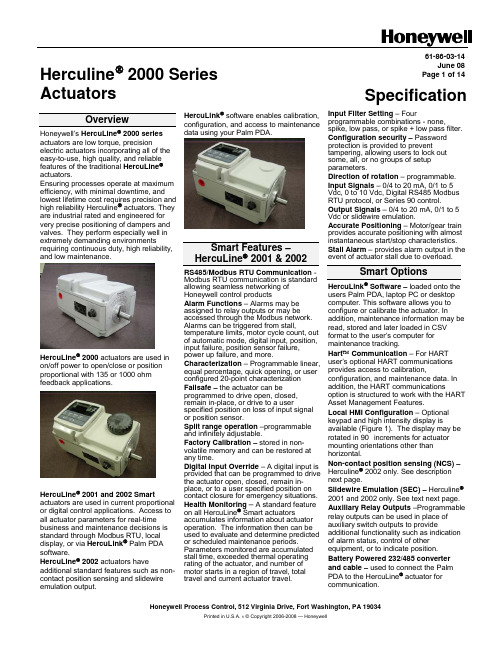
Honeywell Process Control, 512 Virginia Drive, Fort Washington, PA 19034Printed in U.S.A. ν © Copyright 2006-2008 — HoneywellHerculine ® 2000 Series Actuators61-86-03-14June 08Page 1 of 14SpecificationOverviewHoneywell’s HercuLine ® 2000 seriesactuators are low torque, precision electric actuators incorporating all of the easy-to-use, high quality, and reliable features of the traditional HercuLine ® actuators. Ensuring processes operate at maximum efficiency, with minimal downtime, and lowest lifetime cost requires precision and high reliability Herculine ®actuators. They are industrial rated and engineered for very precise positioning of dampers and valves. They perform especially well in extremely demanding environmentsrequiring continuous duty, high reliability, and low maintenance. HercuLine ® 2000 actuators are used inon/off power to open/close or positionproportional with 135 or 1000 ohmfeedback applications.HercuLine ® 2001 and 2002 Smart actuators are used in current proportional or digital control applications. Access to all actuator parameters for real-time business and maintenance decisions isstandard through Modbus RTU, localdisplay, or via HercuLink ® Palm PDAsoftware.HercuLine ® 2002 actuators have additional standard features such as non-contact position sensing and slidewire emulation output. HercuLink ® software enables calibration, configuration, and access to maintenance data using your Palm PDA.Smart Features – HercuLine ® 2001 & 2002 RS485/Modbus RTU Communication -Modbus RTU communication is standard allowing seamless networking of Honeywell control productsAlarm Functions – Alarms may be assigned to relay outputs or may be accessed through the Modbus network. Alarms can be triggered from stall,temperature limits, motor cycle count, out of automatic mode, digital input, position, input failure, position sensor failure,power up failure, and more. Characterization – Programmable linear, equal percentage, quick opening, or user configured 20-point characterizationFailsafe – the actuator can beprogrammed to drive open, closed, remain in-place, or drive to a userspecified position on loss of input signal or position sensor.Split range operation –programmable and infinitely adjustable.Factory Calibration – stored in non-volatile memory and can be restored at any time.Digital Input Override – A digital input is provided that can be programmed to drive the actuator open, closed, remain in-place, or to a user specified position oncontact closure for emergency situations. Health Monitoring – A standard feature on all HercuLine ® Smart actuators accumulates information about actuatoroperation. The information then can be used to evaluate and determine predicted or scheduled maintenance periods. Parameters monitored are accumulated stall time, exceeded thermal operatingrating of the actuator, and number of motor starts in a region of travel, total travel and current actuator travel.Input Filter Setting – Fourprogrammable combinations - none,spike, low pass, or spike + low pass filter.Configuration security – Passwordprotection is provided to prevent tampering, allowing users to lock out some, all, or no groups of setup parameters. Direction of rotation – programmable. Input Signals – 0/4 to 20 mA, 0/1 to 5 Vdc, 0 to 10 Vdc, Digital RS485 Modbus RTU protocol, or Series 90 control. Output Signals – 0/4 to 20 mA, 0/1 to 5 Vdc or slidewire emulation. Accurate Positioning – Motor/gear train provides accurate positioning with almost instantaneous start/stop characteristics. Stall Alarm – provides alarm output in theevent of actuator stall due to overload. Smart OptionsHercuLink ® Software – loaded onto theusers Palm PDA, laptop PC or desktop computer. This software allows you to configure or calibrate the actuator. Inaddition, maintenance information may be read, stored and later loaded in CSV format to the user’s computer for maintenance tracking.Hart ™ Communication – For HART user’s optional HART communications provides access to calibration,configuration, and maintenance data. In addition, the HART communicationsoption is structured to work with the HART Asset Management Features.Local HMI Configuration – Optional keypad and high intensity display isavailable (Figure 1). The display may be rotated in 90° increments for actuator mounting orientations other than horizontal.Non-contact position sensing (NCS) – Herculine ® 2002 only. See description next page.Slidewire Emulation (SEC) – Herculine ®2001 and 2002 only. See text next page.Auxiliary Relay Outputs –Programmable relay outputs can be used in place of auxiliary switch outputs to provideadditional functionality such as indication of alarm status, control of other equipment, or to indicate position. Battery Powered 232/485 converter and cable – used to connect the Palm PDA to the HercuLine ® actuator for communication.61-86-03-14 Page 2Non-Contact Position SensingAvailable in the HercuLine ®2002actuator. The technology is a variableinductance, non-contact position sensor mounted directly to the actuator outputshaft providing precision position sensing from 0 to 150 degrees (Figure 3). Thistechnology eliminates maintenance item such as wipers, bearings, as well asstatic friction, hysteresis and electricalnoise over a wide range of demandingenvironmental conditions. Typically use in very demanding applicati s dons wheredowntime is not an option.Slidewire EmulationAvailable in the HercuLine ® 2001/2002 actuator. The Slidewire EmulationCircuit (SEC) emulates the proportiona voltage output of a typical slidewire through a high impedance circuit. Th voltage output is proportional to the supply voltage and shaft position. If ordered on the 2002 model, a non-contact position sensor is used todetermine shaft position in place o slidewire. Typically used in very demanding applications wher l e f the e downtime is not an option.Potentiometer SensingAn advanced high cycle filmpotentiometer for position sensing for true position feedback is available as option on the Herculine an ndard on Herculine ®2001 EEU model.® 2000 BMUmodel and sta Self-locking/releasingGear TrainThe worm gear output combination is self-locking and self-releasing and maintains position upon loss of power. It is designed to hold greater than two times the rated output torque in a back-driving condition. This design provides superior reliability without themaintenance associated with other self-locking and brake mechanisms. General Features • e thout • ycle – Continuous duty•y out degrading •Hz, single phase <Motor - no burn out motor can b stalled up to 100 hours wi damage to the actuator.Duty C cycle Any position mounting – the actuator may be mounted in an orientation with performance.Power Requirements – Low power consumption 120/240 Vac, 50/60 0.6/0.3 Amp.•X industrial •-•culine ® 2000 series •ification – CSA (pending), UL, CE Enclosure – Rugged, Die cast aluminum NEMA 4grade enclosure.Low Maintenance – Simple proven design means high reliability/low maintenance. Limit Switches – Two end-of-travel electric limit switches are supplied as standard equipment with all Her actuators.• Warranty – Exceptional warranty CertGeneral Options•r PDT switches are •tuator when power is • vailable •s to r ndis & Staefa) •or valve or damper connection.Auxiliary Switches – up to fou additional S available.Manual Operation – a manual hand wheel is optional and used to operate the ac not available.Auto-Manual – electric hand switch with auxiliary contacts indicating an "Out-of-Auto" position is a for local electric control.Competitive Mounting Plates – to adapt the HercuLine ® actuator Invensys (Barber-Colman) o Siemens (La mountings.Linkage assemblies – Pushrod assemblies f61-86-03-14Page 3Optional Local Display and Keypad for HercuLine ® 2001 and 2002A local display and keypad is optional for configuration and set-up (Figure 2). A high intensity 10-character LED display and simple push buttons provide quick access for actuator set up and status information. If relay outputs are specified, all configuration can be done through either the local HMI interface or the HercuLink ® configurator. HercuLink ® Palm PDA software or HART ™ communications is available for those ordering units without the display and keypad.Lower Control Arm RotationPushbuttons (Fou (Six Cha to Access Set Up, Status Calibration Para meters.Figure 1 Local HMI (Display and Keypad)61-86-03-14 Page 4Non-Contact Sensor NCS Spoiler (shown at full150 degree travel CCW)NCS PWA NCS setscrewRelay PWA card guides (relay PWAs removed)Figure 2 Non-Contact Sensor Assembly (HercuLine® 2002)61-86-03-14Page 5HercuLink® Computer InterfaceHercuLink® Computer software enables access to programming and communication functions available as standard with the HercuLine® 2001 and 2002 actuators without the added expense of the keypad & display HMI. Using a Palm™ PDA, laptop PC or desktop computer, HercuLink® software, and a RS232/485 converter users may configure, calibrate, and access maintenance information locally or remotely to the actuator.Using HercuLink® software the computer may be used as a master device over a Modbus network to access information to/from the actuators and to control the device. Set-up configurations may also be stored on the computer for download to other HercuLine®devices. Information may be stored on the users PC in CSV format for use in preventative maintenance programs.•Certified on Palm™ m125, m130, and m505.•Compatible with Palm OS3.5 or higher.•Compatible with Windows 2000 or XP operating systems•Minimum system requirements:•Windows 2000 (w/service pack 2), Windows NT (w/service pack 5), Windows ME, Windows XP•200 MHz Pentium with 64 Megs RamPalm™ is a trademark of Palm, Inc.HotSync® is a registered trademark of Palm Computing, Inc.HercuLink® is a trademark of HoneywellFigure 3 PDA connection61-86-03-14Page 6Set Up/Configuration Parameters for Keypad & Display or HercuLink® SoftwareConfiguration parameters are logically grouped and accessed using the local HMI. Actuator calibration is also accomplished through a simple procedure using the keypad. By pressing the SETUP button on the HMI, you can step through the set up groups that contain all of the configuration parameters. The table below summarizes the configuration parameters available within the various set up groups. Full details of all configuration parameters are found in the HercuLine® 2000 Series Actuator Installation, Operation and Maintenance Manual, document number 62-86-25-10.Set Up Group Configuration Parameter Selections/SettingsSET INPUT⎯Selects various parameters that define actuator operation.IN TYP – Input Actuation TypeINP HI – Input High Range ValueINP LO – Input Low Range ValueFILTYP – Input Filter TypeLPFILT – Low Pass Filter Time ConstantDirect – Actuator RotationDband – Input DeadbandFSFTYPH – FailsafeHI TypeFsFVALH – FailsafeHI ValueFSFTYPL – FailsafeLO TypeFsFVALL – FailsafeLO ValueCHAR – Input Characterization TypeCUST – Custom Characterization TypeSET RELAY⎯When the actuator is equipped with optional relays, this set up group allows you to set relay action for various actuator operating conditions. Contact closure can be wired to external annunciators or alarm points to indicate conditions for any of the Relay Types. RTYPnn – Relay TypeInput RangePosition RangeDeviationUpper or Lower Limit TravelTemperature High or LowCycle CountMotor StalledManual ModePower Up Test FailureInput Signal FailurePosition Sensor Signal FailureDigital Input ClosureTotal Degrees TraveledRnnVAL – Relay ValueRnn HL – Relay High/LowRLYnHY – Relay HysteresisSET CUROUT⎯Selects the current (or voltage) output range of the actuator.CUROUT - Output Signal Range4 – 20 mA 0 – 20 mA1 – 5 V 0 – 5 VOr SWESET COMM⎯Actuator can be defined as a master or slave device on a Modbus RTU RS-485 loop. Operating setpoint can be transmitted to the actuator and operating status can be read when connected to supervisory control M – Communications Parameters ADDRES – Device AddressBAUD – Baud RateXmtDLY – Response DelayDBLBYT – Floating Point Data FormatSET DIGINP⎯Selects digital input action upon contact closure. DIGINP – Digital Input State Endpos – End Position ValueSET DISPLA⎯Selects desired decimal places and engineering units for local display DECMAL – Decimal Point Location EUNITS – Units DisplayUNITS – Display UnitsCAL INPUT, MTR, CURENT⎯If needed, field calibration of the actuator input, motor position and actuator output can be performed using the local keypad and display.61-86-03-14Page 7 Set Up Group Configuration Parameter Selections/SettingsSET LOCK⎯Enables lock out or access to selected set up group parameters and calibration values.LOCKID – Set Security Password LOCK – Lock OutMAENAB – Mode button lockoutREAD STATUS⎯Displays failsafe condition and the results of various diagnostics performed during power up.FAILSF – FailsafeRAMTST – RAM Test DiagnosticSEETST – Serial EEPROM TestDiagnosticCFGTST – Configuration Test DiagnosticCALTST – Calibration Test DiagnosticSET DRVINF⎯Allows access to actuator device information.VERSON – Firmware VersionSPEED – Stroke SpeedPOWER – Power Input Voltage and LineFrequencyTAG – Tag NameDMFG – Manufacturing DateLREP – Date of Last RepairLCAL – Date of Last Field CalibrationREPTYP – Repair TypeSET MAINT⎯Allows access to parameters that monitor operating conditions.TEMP – Actuator TemperatureTEMPHI – High Temperature LimitTEMPLO – Low Temperature LimitACSTA – Accumulated Stall TimeSTARTS – Accumulated Motor StartsRLnCNTS – Relay Cycle CountsREGNn – Accumulated Motor StartsTOTDEG – Total degrees traveledMANRST – Reset Maintenance StatisticsLD CAL – Restore CalibrationLD CFG – Restore ConfigurationSYSRST – System RestartSpecifications – GeneralPhysicalWeight 2000: 25 lb. (11.36 kg)2001,2002: 27 lbs. (12.27 kg)Enclosure Precision-machined die cast aluminum housing, finished in light gray powder coat epoxy. Gear Train Alloy steel, high efficiency steel spur gear primary train. Precision ground, self-locking/selfreleasing worm gear final mesh.Mechanical Stops Factory set at 90° or 150° (+/-5°).Storage Temperature –40 °C to +93 °C (–40 °C to +200 °F)Relative Humidity 0 % to 99 % R.H. non-condensing over the full operating temperature range.Scale 0 % to 100 % corresponding to full crank arm travel.Crank Arm Adjustable radii 1.0 in (25.4mm) to a maximum of 2.8 in (71.1mm). Position adjustablethrough 360° rotation.Output Shaft 0.625+/-.005 in (15.88 +/-.13mm) diameter (round)Rotation 90° or 150° degrees between 0 % and 100 % on scale, limited by mechanical stops. Manual Hand wheel(option)Provides a means of positioning the actuator in the event of a power failure or set-up. Lubrication Texaco Starplex 2 EP GreaseOutput Torque/Full Travel Stroking Time Torque lb-in (N M)50 / (6.0)100 / (11.5)200 / (22.5)400 / (45.0)400 / (45.0)50 Hz (90°/150°)4.5 / 7.59 / 1518 / 3036 / 6054 / 9060 Hz (90°/150°)4 / 67 / 1215/2530/5045/7561-86-03-14Page 8ElectricalMains Supply 100-130 Vac single phase, 50 Hz or 60 Hz200-240 Vac single phase, 50 Hz or 60 HzMotor Instant start/stop, non-coasting, non-burnout, continuous duty, permanent magnet,synchronous induction motor. Can be stalled up to 100 hours without damage.Motor Current = No load = full load = locked rotor = 0.4 amp for 120Vac, 0.2 amp for 240 VacLoss of Power Stays in place on loss of powerLocal Auto/Manual Switch Optional – Allows local and automatic operation of the actuator.End of travel Limit Switches Standard – adjustable to limit actuator travel to less than 90 or 150 degrees respectively Auxiliary Switches/Relays Optional – Up to 4 additional SPDT switches rated at (10 A at 125 Vac, 5 A at 250 Vac). CertificationsApprovals CSA/UL (Standard)CE Compliant (optional)Enclosure Rating Type 4 (NEMA 4), IP66 (standard)Torque Settings of Crank Arm BoltsClamp Bolt 88 lb-in (10 N-m)Electrical and Performance SpecificationsHercuLine® 2000 SeriesHercuLine® 2002 HercuLine® 2001 Herculine® 2000Input Signals Analog:•0/4 to 20 mA (With CPUPWA jumper in currentposition)•0/1 to 5 Vdc•0 to 10 VdcDigital:•Modbus RTU (RS485) Analog:•0/4 to 20 mA (With CPUPWA jumper in currentposition)•0/1 to 5 Vdc•0 to 10 Vdc•Series 90 controlDigital:•Modbus RTU (RS485)120 Vac drive open/120 Vacdrive close240 Vac drive open/240 Vacdrive closeIsolation Input signal, output signal and power are isolated from eachother.NA Load Requirement (4-20) Current Out — 0 to 1000 ohms NAInput Impedance 0/4 to 20 mA0/1 to 5 Vdc0-10 Vdc 250 ohms10 K ohmsNA0 to 20 mA, 4 to 20 mA0 to 5 Vdc & 1 to 5 Vdc with 250 ohm resistor, (0 to 16 Vdc with 800 ohm resistor) Dual output 1000 ohms over 90 degrees (135 ohms with 158 resistor)Dual output 1000 ohms over 150 degrees (135 ohms with 158 resistor)FeedbackSlidewire emulation - Provides output voltage ratiometric toshaft position and potentiometric to supply voltage(1 Vdc to 18 Vdc) without a slidewire. Emulates a 100 ohm to1000 ohm slidewire. 10 mA output maximum.61-86-03-14Page 9HercuLine® 2002 HercuLine® 2001 Herculine® 2000 Communications Modbus RTU or optional HART™NAOperating Temperature –40°C to +75 °C (–40°F to +170 °F) -40°C to +85 °C (-40°F to+185 °F)Position sensing Non-contact position sensor 1000 ohm film potentiometer Optional dual 1000 ohm filmpotentiometersSensitivity 0.2 % to 5 % of 90° span, proportional to deadband NAHysteresis Less than 0.4 % of full scale NADeadband 0.2 % to 5 % of 90° span, programmable. Shipped at 0.5 %NARepeatability 0.2 % of 90° span NARepositions(minimum @ 90 or 150degree stroke)Table 1 option –050- Table 1 option –100- Table 1 option –200- Table 1 option –400- Table 1 option –600- 160290450700900120250400400400500Voltage/ SupplyStability0.25 % of span with +10/–15 % voltage change NATemperature Coefficient Less than ± 0.030 % of span per degree C for 0 °C to 50 °CLess than ± 0.05 % of span per degree C for –40 °C to 75 °CNAZero Suppression 90 % of span.NA Input Filters Selectable spike and low pass filters.NASolid State Motor Control Two triac switches for clockwise or anti-clockwise motoroperation. Transient voltage protection provided.NAFailsafe operation If input signal exceeds configured input range. Selectable andadjustable.NA Direction of Rotation Field programmable Wire swap Duty Cycle ContinuousProgrammableFunctionsSelectable and configurable operating parameters:NA• Inputrange• Inputfiltering• Inputcharacterization• Security•Digital Input action• Deadband•Failsafe on loss of input signal•Failsafe on loss of position sensor•Direction of rotation•Relay closure action• Communicationparameters•Split range operation• Outputrange• Alarms61-86-03-14Page 10Actuator Crank ArmThe HercuLine® 2000 Series Actuators come standard with a 2.8 inch (71.12mm) crank arm (Figure 4). The crank arm uses linkage kits (above). Adjustable radius (1.0 in (25.4mm) to 2.80 in (71.12mm)). Position adjustable through 360° rotation.Figure 4 Standard 2.8” (71.12mm) Crank ArmFigure 5 Crank Arm with optional ball joint and push rodModel Selection GuidecontinuedOutline Dimension DrawingsmminchesActionator M640A, M740A, and M940A replacementSee Honeywell SalesNet at /salesnet/supporting_docs/sales_tools/actionator_to_hl_xover.xlsWarranty/RemedyHoneywell warrants goods of its manufacture as being free of defective materials and faulty workmanship. Contact your local sales office for warranty information. If warranted goods are returned to Honeywell during the period ofcoverage, Honeywell will repair or replace without charge those items it finds defective. The foregoing is Buyer's sole remedy and is in lieu of all other warranties, expressed or implied, including those of merchantability andfitness for a particular purpose. Specifications may change without notice. The information we supply is believed to be accurate and reliable as of this printing. However, we assume no responsibility for its use.While we provide application assistance personally, through our literature and the Honeywell web site, it is up to the customer to determine the suitability of the product in the application.For more information, contact Honeywell sales at (800) 343-0228.Honeywell Process ControlHoneywell512 Virginia DriveFort Washington, PA 1903461-86-03-14 June 08 Printed in USA /ps。
KA5H0265RC中文资料

Operating Junction Temperature. Operating Ambient Temperature. Storage Temperature Range.
Symbol
VDGR VGS IDM
ID ID EAS VCC,MAX VFB PD Darting TJ TA TSTG
21 -
28 nS
77 -
24 -
- 60
15
-
nC
20 -
Note: 1. Pulse test: Pulse width ≤ 300µS, duty cycle ≤ 2% 2. S = -1--
R
3
元器件交易网
KA5X02XX-SERIES
Electrical Characteristics (Control Part) (Continued)
(MOSFET switching time is -
essentially independent of -
operating temperature)
-
VGS=10V, ID=1.0A, VDS=0.5B VDSS (MOSFET
-
switching time is essentially independent of operating
Features
• Precision Fixed Operating Frequency (100/67/50kHz) • Low Start-up Current (Typ. 100uA) • Pulse by Pulse Current Limiting • Over Load Protection • Over Voltage Protection (Min. 25V) • Internal Thermal Shutdown Function • Under Voltage Lockout • Internal High Voltage Sense FET • Auto-Restart Mode