格林威尔 GPN710开通配置指导
陕西联通分组传送网承载大客户专线业务典型设计(格林威尔)--9.5改图-1_59

陕西联通分组传送网承载大客户专线业务典型场景设计手册格林威尔分组接入设备2016年08月目录一、联通IPRAN承载政企客户专线背景 (3)二、陕西联通IPRAN承载政企客户专线实施中的问题及建议解决方案 (5)2.1IPRAN承载政企客户专线实施中的问题 (5)2.2建议解决方案(基站汇聚上行) (6)三、IPRAN承载大客户专线业务需求速查表(格林威尔) (8)四、IPRAN承载大客户专线业务方案模型 (9)4.1点对点方案模型-1(终端直挂) (9)4.1.1业务需求情况 (9)4.1.2业务模型示意图 (10)4.1.3业务开通描述: (10)4.1.4设备配置模型 (10)4.2点对点方案模型-2(基站汇聚) (10)4.2.1业务需求情况 (10)4.2.2业务模型示意图 (11)4.2.3组网模型描述 (11)4.2.4设备配置模型 (11)4.3点对点方案模型-3(基站汇聚) (12)4.3.1业务需求情况 (12)4.3.2业务模型示意图 (12)4.3.3组网模型描述 (12)4.3.4设备配置模型 (13)4.4点对多点方案模型-1(终端直挂) (13)4.4.1业务需求 (13)4.4.2业务模型示意图 (13)4.4.3组网模型描述 (13)4.4.4设备配置模型 (14)4.5点对多点方案模型-2(基站汇聚) (14)4.5.1业务需求 (14)4.5.2业务模型示意图 (15)4.5.3组网模型描述 (15)4.5.4设备配置模型 (15)4.6点对多点方案模型-3(基站汇聚) (16)4.6.1业务需求 (16)4.6.2业务模型示意图 (16)4.6.3组网模型描述 (16)4.6.4设备配置模型 (17)4.7自组网模型 (17)4.7.1业务需求 (17)4.7.2业务模型示意图 (18)4.7.3组网模型描述 (18)4.7.4设备配置模型 (19)五、格林威尔分组产品介绍 (19)一、联通IPRAN承载政企客户专线背景集团客户业务收益高,相对于一般用户,通常具有业务量大、业务安全性要求高等特点,随着信息技术的发展,集团客户业务呈现宽带化和IP化的发展趋势。
格林威尔调试

格林威尔PCM局端开局(E1 8:8模式)今后很多地方都要用格林威尔的PCM了,没搞过的好好看看啊,我把网管里需要改动的配置贴出来,大家好好研究研究~1,端口设置在工具--端口里面加入port0 类型UDP 参数161,162port1 类型UDPRedirect 参数3161port2 类型UDP 参数3166,3167,添加局端设备IP(南通局是192.168.0.11)以上3个端口全部激活,局端网络选中Port0,厂站网络选中port22,创建网元,地址先设为默认的地址192.168.6.120 访问串都设为private,通过Ethernet口连接电脑即可管理到设备3,双击PCM,可以设置系统的一些信息,把IP地址改为规划好的,Trap配置里网号及站号和Trap IP设成主站的参数,团体字设为private 。
用来传递告警等信息到局端设备4,路由表设置,网号站号为对端的PCM,对于B120B设备协议选2,E1端口是指本端设备用第几个端口连接的。
若不设则管不到对端设备5,双击E1图标,设置2M板的一些参数,需要注意的是要把HDLC通道设成“时隙0”,否则代理不到对端设备6,用户板设置,在12:4模式下,默认配置是第1个E1对应第1和2个用户板,第2个E1对应第3和4个用户板,第3个E1对应第5和6个用户板,第4个E 1对应第7和8个用户板,只能用4个E1,达不到用户的要求。
现在通过手动配置把第1,2,3,4个E1对应第1,3,5,7个用户板,第5,6,7,8个E1对应第2,4,6,8个用户板,如下所示双击Slot2即用户板2,把起始时隙从原来的(E1-13 :17)--(E 1-13 :31)改成(E1-9 :1)--(E1-9 :15)双击Slot4即用户板4,把起始时隙从原来的(E1-14 :17)--(E 1-14 :31)改成(E1-10 :1)--(E1-10 :15)双击Slot4即用户板6,把起始时隙从原来的(E1-15:17)--(E1 -15 :31)改成(E1-11 :1)--(E1-11 :15)双击Slot4即用户板8,把起始时隙从原来的(E1-16 :17)--(E 1-16 :31)改成(E1-12 :1)--(E1-12 :15)7,DXC设置,单击初始化设置,勾选“同时初始化数据与信令DXC”的选项,工作模式选择8:88,第6和第7的步骤是局端需要一台PCM对应8个E1的时候才要的,变电所侧不需要配置没碰过网管肯定看不懂,把这个文档放在电脑里以备不时只需,附带的图片仅作参考~附件:格林威尔.rar (227.05KB)回复引用2#作者姓名:李栋2011-01-11 21:55:15写的很详细,很不错回复引用3#作者姓名:周跃2011-01-13 00:05:34第一步先用串口线连接CONSOLE口,波特率为19200----进去后输入setip输入I P地址进入网管回复引用4#作者姓名:赵耀2011-01-23 15:29:02周跃的是老方法,不方便,后来周旭发过ETH连接的新办法,就是这个192.168.6.120回复引用5#作者姓名:王亚春2011-01-24 19:06:12大家一定要学会使用网管,特备是本地网管和远程网管是如何设置。
格林威尔GPN710-B-4FE4E1常规配置(小型PTN)
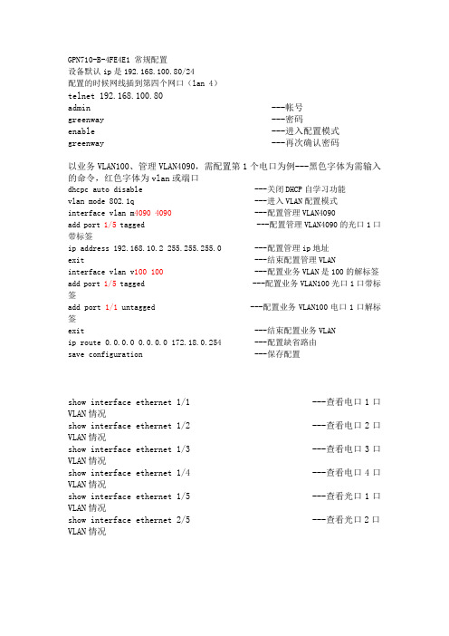
GPN710-B-4FE4E1 常规配置设备默认ip是192.168.100.80/24配置的时候网线插到第四个网口(lan 4)telnet 192.168.100.80admin ---帐号greenway ---密码enable ---进入配置模式greenway ---再次确认密码以业务VLAN100、管理VLAN4090,需配置第1个电口为例---黑色字体为需输入的命令,红色字体为vlan或端口dhcpc auto disable ---关闭DHCP自学习功能vlan mode 802.1q ---进入VLAN配置模式interface vlan m4090 4090 ---配置管理VLAN4090add port 1/5 tagged ---配置管理VLAN4090的光口1口带标签ip address 192.168.10.2 255.255.255.0 ---配置管理ip地址exit ---结束配置管理VLANinterface vlan v100 100 ---配置业务VLAN是100的解标签add port 1/5 tagged ---配置业务VLAN100光口1口带标签add port 1/1 untagged ---配置业务VLAN100电口1口解标签exit ---结束配置业务VLANip route 0.0.0.0 0.0.0.0 172.18.0.254 ---配置缺省路由save configuration ---保存配置show interface ethernet 1/1 ---查看电口1口VLAN情况show interface ethernet 1/2 ---查看电口2口VLAN情况show interface ethernet 1/3 ---查看电口3口VLAN情况show interface ethernet 1/4 ---查看电口4口VLAN情况show interface ethernet 1/5 ---查看光口1口VLAN情况show interface ethernet 2/5 ---查看光口2口VLAN情况。
医学格林威尔DA网管系统操作指南课件

返回目录
4.2 添加E3300、E3600系列
在网管客户端软件的界面上,如下图所示选择创建对象,
返回目录在路径创建页面中点击宿选项后的浏览进入宿节点配臵首先在槽位中选择maspe6300主交叉板然后选择端口1stm1物理端口再次vc4中选择1也就是vc41最后选择时隙号此时的时隙号为155m光口上给这个业务分配的时隙号需要向传输工程师询问此时隙号
格林威尔DA网管系统操 作指南
目录
目录 1.网管软件的安装 1.1安装网管软件的硬件需求 1.2安装网管软件所需的文件系统(平台、网元全套) 1.3安装网管软件 1.4网管模块的安装 1.5网元信息的查询与更改 2.启动服务器和客户端 3.网管软件的权限设置(用户名,密码。分权分域) 4.网管系统上网元的添加 4.1添加E6300、E6100、E6080系列 4.2添加E3600、E3300系列 4.3添加GFT2000系列 5.网管上数据的配置 5.1数据配置举例 5.2远端设备配置 6告警
1
备注 选配 必配
返回目录
1.2安装网管软件的软件需求
安装DA网管平台: 文件名称:UniView DA V3.0 安装DA网管网元模块: E 6300,E6100,E 6080系列: UV_DA_MSTP V3.0 E3600,E3300系列:UV_DA_MSAP V3.0 GFT2000系列: UV_DA_GFT2000 V3.0
• 在路径创建页面中,点击宿选项后的浏览,进入宿节点配置,首先在槽位中选择 “MASP-E6300主交叉板”,然后选择端口“1#STM-1物理端口”,最后选择时隙号(此 时的时隙号为155M光口上给这个业务分配的时隙号,需要向传输工程师询问此时隙号);
710相关配置指导书
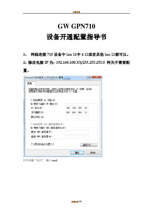
GW GPN710设备开通配置指导书1:网线连接710设备中lan口中4口或者其他lan口都可以。
2:修改电脑IP为:192.168.100.XX/255.255.255.0 网关不需要配置。
打开电脑“运行”输入cmd进入之后输入“telnet 192.168.100.80”所有新出厂710设备都是这个IPLogin:admin Password:greenway输入en Password:greenway 进入config模式然后直接把脚本黏贴进去,复制之后,黏贴进去。
如需创建上联端口链路聚合保护组请略过此步骤。
然后回车出现此打印信息表示保存成功。
输入show running-config 命令可以查看配置信息端口号分配解释:1/1为电口一,1/2为电口二,1/3为电口三,1/4为电口四。
1/5为光口一,1/6为光口二。
※步骤解释※单光口上联GPN710-B-4FE4E1-V1>enPassword:greenway(输入密码时显示为密语,看不到自己的输入信息)GPN710-B-4FE4E1-V1(config)#dhcpc auto disable (dhcp功能关闭)GPN710-B-4FE4E1-V1(config)#vlan mode 802.1q (vlan功能使能)GPN710-B-4FE4E1-V1(config)#interface vlan guanlivlan 105(105为管理vlan ,guanlivlan为vlan名称,这两项可根据实际需求更改)GPN710-B-4FE4E1-V1(vlan-guanlivlan)#ip address 172.168.6.33 255.255.255.0(172.168.6.33 255.255.255.0为管理IP/掩码根据实际情况改)GPN710-B-4FE4E1-V1(vlan-guanlivlan)#add port 1/5 taggedGPN710-B-4FE4E1-V1(vlan-guanlivlan)#exitGPN710-B-4FE4E1-V1(config)#ip route 0.0.0.0 0.0.0.0 192.168.230.1(192.168.230.1为管理网管根据实际更改)GPN710-B-4FE4E1-V1(config)#config snmp trapreceiver add 192.168.194.254 version v2c public (192.168.194.254为格林威尔网管服务器的IP地址,根据实际情况更改。
格林威尔开通维护指导书

格林威尔开通维护指导书(总37页)-CAL-FENGHAI.-(YICAI)-Company One1-CAL-本页仅作为文档封面,使用请直接删除格林威尔产品开通指导书800-810-92921一局端汇聚设备MSAP-E6300P设备简介E6300P整机如图所示,其采用19英寸(宽)4U(高)插卡式结构,最多可以插19张盘。
电源盘,主控盘,上联盘为固定槽位,12个槽位可混插各种业务接口盘。
前面板示意图:图1-1 E6300P前面板示意图E6300P机框主体分为19个槽位,编号从左到右依次编为1到18。
其中7和7A槽位插入GE上联盘。
□1~6号槽位是业务盘槽位,支持业务盘混插;□多块EC63板卡安装时,可提前联系工程师,由工程师根据情况确定槽位号□7和7A号槽位是千兆以太网上联盘,固定槽位;□8号槽位是主控盘,固定槽位;□9、10号槽位是上联盘,固定槽位;□11~16号槽位是业务盘槽位,支持业务盘混插;□17、18号槽位是电源盘,固定槽位。
□E6300P机框还包括风扇盘,在机框的顶部,每块盘有三个风扇,并且有相应的告警指示灯。
1告警输出告警输入保护地-48V 电源1-48V 电源2图1-2 E6300P 后面板示意图网管2:以太网网管接口,连接设备网管时使用□输入电压范围:-36V~-72V(直流)、130V~250V(交流)□整机功率(满配,包括2块OMU,2块电源板,1块NMU和12块A120,风扇):小于55W(25℃);NMU功率:<;OMU功率:<5W业务盘介绍电源盘E3US-PWUPWUAC220V+5VAC220V IN图1-3 -48V电源盘面板图图1-4 220V电源盘面板图E3US-PWU-48指示灯说明:□-48V灯亮,表示-48V电源正常。
□5V绿灯亮,表示该电源盘的5V输出正常;5V红灯亮,表示该电源盘的5V 输出出现故障;5V灯灭,表示整个设备的5V输出出现故障。
E3US-PWU-220指示灯说明:□220V灯亮,表示220V电源正常。
格林威尔网管功能业务开通培训讲义.pptx
在建立完网管,并 能正确连接到网元 时,为了了解网元 侧的已有信息,需 要先对网元侧数据 做上载。网元图标 上右键<维护>---< 数据库表上下载>: 进入数据库表上 下载界面:
基础信息配置
数据库上载并校 验匹配性:
在建立完网管,并 能正确连接到网元 时,为了了解网元 侧的已有信息,需 要先对网元侧数据 做上载。网元图标 上右键<维护>---< 数据库表上下载>:
基础信息配置
网元信息配置: 选择<登录信息>页面,设置是否自动登录,修改网元登录密码,点击< 应用>按钮,使修改生效。
基础信息配置
网元信息配置: 选择<IP地址设置>页面,修改IP地址。
基础信息配置
网元信息配置: 选择<网关网元设置>页面,设置网元是否为网关网元,如果是网关网 元,需要设置网元的通信级别;支持查询网元的实际网关网元。
3、删除区域管理:在拓扑图中选择管理对象,在菜单<拓扑>中选择 <删除设备>,将对象删除。注意区域下有局站和设备时,需要按层删 除,先网元,再局站,最后区域。
基础信息配置
局站管理:
1、选中要添加局站的区域。 2、在菜单<拓扑>中选择<创建对 象> ,填写局站名称,在种类中选择 局站 图示(第三个),点击<下一步>, 完成 局站管理的添加。 3、修改局站管理:在拓扑图中 选择 管理对象,在菜单<拓扑>中选择 <被 管对象属性>,修改局站的属性 信息。 4、删除局站管理:在拓扑图中 选择 管理对象,<拓扑>中选择<删除 设备 >,将对象删除。注意局站下有 网元
Power 710 (9123-710) 快速入门指南说明书
Quick start guide for OpenPower710(9123-710)1Before you beginThis Quick start guide contains an abbreviated set of setup instructions designed to help you quicklyunpack and set up a standard ers unfamiliar with this IBM hardware should use the fullydetailed,setup instructions that you can find in the IBM Systems Hardware Information Center.For details about how to access the information center,see task 9.Finish your system setup The exclamation mark surrounded by a gray triangle denotes caution.A CAUTION notice indicates the presence of a hazard that has the potential of causingmoderate or minor personal injury .Before doing a step that contains a caution icon,read and understand the caution statement that accompanies it.Use safe practices when lifting.Rack-mounted devices are not to be used as a shelf or workspace.Do notplace any object on top of rack-mounted devices.®CAUTION:The weight for this part or unit is between 18 and 32 kg (39.7 and70.5 lbs).It takes two persons to safely lift this part or unit.(C009)Inventory 22.1Complete an inventory of the external parts.Locate the kitting report (inventory list) in the bag that contains the informationcenter CD (SK3T -8159).Make sure you received all of the parts that you ordered.Y our order information should be located in an envelope adhered to the outsideof your system box.Y ou can also obtain order information from your marketingrepresentative or IBM Business Partner.If you have incorrect,missing,or damaged parts,consult any of the followingresources:Y our IBM resellerIBM Rochester manufacturing automated informationline at 1-800-300-8751(United States only)Directory of worldwide contacts at /planetwide.Select your location to view the service and support contact information.2.2Y ou will need the following parts:Cable-management arm Rack-mounting hardware kitScrews233.1 3.2 3.3If you are installing your server into a new rack,ensure that you have completed the unpacking instructions that were provided with the rack.If your s is already installed in a rack,skip to task 7Place the rack in the location of the installation.Use the wrench that was provided with your rack to level the rack by raising or lowering the front and back leveling feet.Install the stabilizer bracket on the front of the rack.If necessary,remove any trim kit pieces that were previously installed on the rack.Removing the trim kit pieces allows you to read the EIA units on the rack..ABTip:erver Cable the HMC and the server3.4Prepare the rack for installationAB4.1Determine where in the rack to place the server.This server occupies two EIA units.Remove any filler panels necessary to allow adequate access to the location whereyou will install your server.If you do not have enough space around your rack to open the front and back doors completely,remove the doors before starting this task to allow adequate access.Install the slide rail assemblies 44.2Install the slide rail assemblies.Pull the front and back blue latch-assembly release tabs and use the bluetabs to push the latch assembly into the retracted position.Make sure bothB C A 1.Front viewNote:Install units into the lower part of the rack first.Place larger and heavier unitsin the lower part of the rack.4.3 4.4()Optional Finger-tighten the system-retaining screws into the backslide-rail bracket holes on the back of the rack.ABFrom the back of the rack,place the front rack flange between the front slide-rail flange and the retracted front-alignment pins.Press the release tab to extend the pins into the holes.Align the back alignment pins with the correct holes in the back rack-flange and press the latch assembly release tab to extend the pins into the back of the rack.Ensure that the pins are in the correct holes and that the slide rail assemblyEF DA DEAD2.3.4.Front view55.6Use a screwdriver to tighten the system-retaining screws that you may haveinstalled in step 4.3.alignInstall the server onto the slide rail assembly Before you begin:Read this entire task before completing any individual steps.Before installing the server onto the slide rail assembly,ensure that the leveling feet are extended and that the stabilizer bracket is correctly installed to prevent the rack from falling forward.6.1Locate the cable-management arm and the two pins .E A 6Install the cable-management arm6.3From the back of the rack,use the pin to affix the cable-management arm to the left slide rail management arm flange that is attached to the rack frame .A E D --6.2Use the second pin to affix the other end of the cable-management arm to the flange that is attached to the sliding portion of the left slide rail assembly .A CB E Tip:If space is limited inside the rack,slide the server out part of the way to installthe cable-management arm.7.17.27.3Route the power cords through the rings or clamps,if available,andconnect to the server,monitor,and HMC.Do not connect the powercords to a power source until instructed to do so.7.4Attach the monitor cable to the monitor connector on the HMCand tighten the screws.Tip:If you are using the rack-mounted LCD monitor and keyboard (7316-TF3),use the C2T -to-KVM adapter breakout cable to attach to the HMC.A Hardware Management Console (HMC) is a system that connects to the server and manages it through a network.If you are using a rack-mounted HMC,these steps assume that it is already installed in the rack.If you need to install the HMC into the rack,follow the instructions in the IBM Systems Hardware Information Center,and return to this guide when you are ready to begin cabling your HMC.For details about how to access the information center ,see task 9If you are not using an HMC to manage your server,you can use the IntegratedVirtualization Manager (IVM),a graphics terminal,or an ASCII terminal.If you plan to use IVM,which allows you to create and manage partitions,skip to task 8.For information about the other console options,go to the IBM Systems Hardware Information Center.For details about how to access the information center,see task 9.Cable the server and access the Integrated Virtualization Manager Finish your system setup Finish your system setup.If you are using any optional adapters for the HMC,connect the cables to the appropriate adapter connectors in the PCI slots of your server and HMC.Cable the HMC and the server7Connect the mouse and keyboard cables to the appropriate ports on the back of the HMC.If your mouse and keyboard use Universal Serial Bus (USB) cables,you can connect these to the ports on the front of the HMC.Important:Ensure that if there is a voltage switch next to the powerconnector on the monitor,it is in the appropriate position for the voltageused in your geography.7.57.6If you are not using a modem,skip to step 7.6.If you are using the integrated HMC modem,connect the telephone cable to the modem and to the analog jack on the wall.If you are using an external modem,connect the modem data cable to the external modem and to a serial port on the HMC.Then connect the telephone cable to the external modem and to the analog jack on the wall.Connect the Ethernet cable to the Ethernet port on the HMC and tothe Ethernet port labeled HMC1on the server.For a stand-alone HMC,use the integrated Ethernet port.For the 7310-CR2rack-mounted HMC,use the bottom-right Ethernet port.For the 7310-CR3 rack-mounted HMC,use the left port of the two planar board Ethernet ports.7.77.87.9If using an external modem,plug the power cord into the modem.CAUTION:This product is equipped with a 3-wire (two conductors and a ground) power cable and e this power cable with a properly grounded electrical outlet to avoid electrical shock.(C018)Y ou have completed the basic setup.Go to task 9Route the cables through the cable-management arm on the server,and secure the cables with the straps provided.Start and configure the HMC,which includes the Guided Setup Wizard.Y ou canfind the instructions for configuring the HMC in the IBM Systems Hardware Information Center.For details about how to access the information center,see task 9Finish your system setup.7.10Connect the s to a power source and wait for the control panel on the front of the server to display .This might take several minutes.erver ,017.11Press the white Power On button on the control panel.Plug the power cords for the monitor,HMC,and external modem into a power source.Do not connect the server to a power source until instructed to do so.7.128.1Connect one end of a serial cable to the system port on your server,and the otherend to a serial port on a PC that has Microsoft Internet Explorer 6.0,Netscape 7.1,orOpera 7.23 installed.8Connect an Ethernet cable from the PC to the port labeled HMC1on the back ofthe server.If HMC1is occupied,use the port labeled HMC2.If you are using any optional adapters,connect the cables to the appropriateadapter connectors in the PCI slots of your server and PC.Cable the server and access the Integrated Virtualization Manager CAUTION:This product is equipped with a 3-wire (two conductors and aground) power cable and e this power cable with a properlyon the back of the8.38.48.88.6At the login promopt,enter the following default user ID and password:In the navigation area,expand .Click .Select in the Boot to system server firmware field.Click .Power/Restart Control Power On/Off System Standby Save settings and power on User IDadmin Password admin Configure the Ethernet interface on the PC to an IP address and subnet maskwithin the same subnet as the server.This is the IP address for the serviceprocessor.Server connectorHMC1HMC2Subnet mask 255.255.255.0255.255.255.0IP address 192.168.2.147192.168.3.147For example,if you connected your PC to HMC1,the IP address for your serviceprocessor might be 192.168.2.1and the subnet mask would be 255.255.255.0.Setthe gateway IP address to the same IP address as that of the PC.Using a Web browser,enter the IP address into the field that correspondsto the port to which your PC is connected.For example,enter https://192.168.2.147.Address Possible values:Note :If you do not know how to do this,see the instructions in the IBM SystemsHardware Information Center.For details about how to access the informationcenter,see task 9Finish your system setup.When you are prompted,change the default password.8.78.108.91.2.3.4.Change the state of the system server firmware.8.5Route the cables through the cable-management arm and secure the cables to the cable-management arm.8.12Open a terminal session on the PC,using an application such asHyperT erminal.Be sure the line speed is set to 19,200 bits per second to communicate with the system.8.15Change the partition mode.Insert the Virtual I/O Server CD into the optical drive of the system.1.2.3.4.5.In the navigation area,expand .Click .Select in the AIX/Linux partition mode boot field.Select in the Boot to system server firmware field.Click .Power/Restart Control Power On/Off System Boot to SMS menu Running Save settings and continue system server firmware boot 8.13 1.2.3.4.In the ASMI navigation area,expand .Click .Select in the AIX/Linux partition mode boot field.Click .Power/Restart Control Power On/Off System Continue to operating system Save settings 8.14Change the partition mode back so that the server continues to load the operating system during startup.8.11After the system has reached the firmware standby state,enter the activationcode for the Virtualization Engine technologies.TM In the navigation area,expand .Click .Enter the activation key into the field.This key was included with the printedmaterial inside your system box.Click .The Advanced POWER Virtualization feature is enabled.On Demand Utilities CoD Activation Continue 1.2.3.4.1.2.3.4.Select the console,and press Enter.Select a language for the BOS menus,and press Enter.Select .Select .The managed system restarts after theinstallation is complete,and the login prompt is displayed on the ASCIIterminal.Start Install Now with Default Settings Continue with Install 8.17Install the Virtual I/O Server.8.16When the system management services (SMS) menu is displayed in theterminal session over the connection that you set up in step 8.1,chooseand follow the menu options to set the optical drive asthe initial boot device.Select Boot Options Tip:Additional Information about the Virtual I/O Server,such as how to check forupdates,configure network connections,and configure partitions,is located in theIBM Systems Hardware Information Center.Y ou have completed the basic setup.Continue to task 9Finish your system setup.Finish your system setup9Using a Web browser,go to /systems/infocenter/hardware or go tothe preinstalled version on the HMC.Answer the questions in the interactive interview,and follow the procedures in theresulting checklist.From the navigation bar,click Systems Hardware information OpenPowerinformation Initial server setup Create a customized initial server setup checklist.>>>Y ou have completed the basic tasks to set up your server.Y ou can access the .Follow these steps to create a customized checklist that helps you configure your server and console,install software,apply fixes,and establish connections with your service provider:now IBM Systems Hardware Information Center If you cannot access the online version of the information center,it is also provided on a CD with your system (SK3T -8159).9.19.29.3International Business Machines Corporation 2005,2007Printed in USASeptember 2007All Rights ReservedMail comments to:IBM CorporationAttention Department DDR3605 Highway 52 NorthRochester,MN U.S.A.55901-7829Fax comments to:1-800-937-3430 (U.S.or Canada)1-507-253-5192 (outside the U.S.or Canada)Internet URL: http://www /systems/infocenter/hardware References in this publication to IBM products or services do not imply that IBM intends to make them available in every country or region.,IBM,the IBM logo,andOpenPower are trademarks of International Business Machines Corporation in the United States,othercountries or both.Other company ,product,and service names may be trademarks or service marks of others.e (logo) server,eServer Microsoft,Windows,Windows NT ,and the Windows logo are trademarks of Microsoft Corporation in the United States,other countries,or both.SA41-5159-0629R1708。
FDD-LTE LN7.0开通手册
BTS为基站硬件数据 TRS为基站传输数据
选择所需的脚本进展配置
按实际硬件配置填写
按规划信息填写
主用备用OMS 根据现网OMS承载来定 按地市所提供的ip地址填写
传输端口模式强制千兆
管理面IP 依据传输规划填写
业务面IP 依据传输规划填写
IP 要正确填写
时钟同步设置
路由信息 按规划填写网关地址
按规无线划填写
通道组按规无线划
按无线规划填写
按运营商要求填写
按无线规划填写
按无线规划填写所有参数
按无线规划填写
下发数据
FDD-LTE LN7.0开通手册
1. 需要使用软件 BTS Site Manager (ltesdkroot)_LN7.0_BTSSM_1407_107_00 LN7.0_ENB_1407_581_42_release_BTSSM_downloadable
2. 电脑IP设置 IP地址:子网掩码 :
本地电脑直连BBU,选择Local 后台网管连接BBU,输入基站网管IP地址
ห้องสมุดไป่ตู้登入用户名:Nemuadmin 登入密码:nemuuser
可选择已安装的版本,点击 Create用于离线制作
可选已保存的基站快照,进 展数据核对等
选择升级软件选项
选择所需的软件包升级 点击Update,升级完大约12分钟左右
新格林耐特配置命令
第一部分:TiNetS2000EI系列配置命令及说明(红色标识为一些常用命令)Username(1-32chars):adminPassword(1-16chars):******/登陆交换机,默认密码123456/TiNet>enable/进入特权模式/TiNet#configureterminal/进入全局模式/TiNet(config)#1.TINET#terminallanguage/改变语言模式/例如:TINET#terminallanguageChinese/改成中文模式/2.TiNet#clearstartup-config/清除配置,恢复出厂默设置/3.4.5./6.7.8.9./ 10.11.12./端口为trunk模式,允许所有VLAN通过/13.TiNet(config-if-ethernet-0/2)#switchportaccessvlan1001/改变端口PVID/14.TiNet(config)#port-isolationethernet?STRING<3-4>端口号为槽端口号<0-2>/端口号<1-24>TiNet(config)#port-isolationethernet0/2toe0/16添加端口隔离下行端口成功./一步隔离,一条命令隔离除上行口以外所有端口/15.TiNet(config)#interfacerangeethernet0/2toethernet0/16/批量端口处理命令/16.TiNet(config-if-range)#bandwidth-control?egress出口带宽控制ingress入口带宽控制/端口限速命令/17.TiNet(config)#showutilizationinterface/实时查看端口流量占比/LinkUtilizationAveragesThuJan100:43:201970portlinkReceivePeakRxTransmitPeakTxStatuspkts/secpkts/secpkts/secpkts/sec==================================================================e0/1down0000e0/2down0000e0/3down0000e0/4down0000e0/5down0000e0/6down000018.简要流程/配置ip地址/ConfigIPsuccessfully.TiNet(config)#showipSwitchconfigurationipobtained:MANUALnetmask:ManageVLAN:1MACaddress:00:0a:5a:11:ba:b8/查看交换机ip地址/TiNet(config)#exTiNet#terminallanguagechinese/更改语言模式为中文/TiNet(config)#vlan3901/建立vlan3901/TiNet(config-if-vlan)#switchportall/在vlan3901下添加端口/添加VLAN端口成功!TiNet(config)#ipaddressvlan3901/定义交换机管理vlan/配置管理VLAN成功!TiNet(config)#showip交换机的配置信息IP地址获得方式:MANUAL管理VLAN:13901/此时管理vlan为1和3901/MAC地址:00:0a:5a:11:ba:b8IP管理MAC添加显示添加TiNet(config-if-vlan)#showvlan1015显示VLAN信息VLANID:1015VLANstatus:staticVLANmember:e0/1,e0/16.Statictaggedports:StaticuntaggedPorts:e0/1,e0/16.Dynamictaggedports:TiNet(config)#port-isolationethernet0/2toe0/16/端口2-16进行隔离,1口为上行口,未隔离/添加端口隔离下行端口成功.TiNet(config-if-ethernet-0/1)#switchport?accessaccess端口backup配置备份端口mode端口模式trunktrunk端口TiNet(config-if-ethernet-0/1)#switchportmodetrunk/更改端口1模式为trunk/ TiNet(config-if-ethernet-0/1)#switchporttrunkallowedvlanall/允许所有vlan通过1口/ TiNet(config-if-ethernet-0/1)#switchporttrunknativevlan3901/更改1口pvid为3901/请输入您的登录密码:******请输入用户名(4--15位):admin请输入新口令(1--15位):******输入确认口令(1--15位):******/用户admin密码修改成功/ TiNet#copyrunning-configstartup-config/保存配置命令/第二部分:交换机实现telnet管理配置步骤第一步:配置规划好的交换机ip地址例:/配置ip地址/ConfigIPsuccessfully.TiNet(config)#showipSwitchconfigurationipobtained:MANUALManageVLAN:1MACaddress:00:0a:5a:11:ba:b8/查看交换机ip地址/第二步:建立规划好的管理vlan,把上行口加入到管理vlan中,然后删除默认的管理vlan1 例:TiNet(config)#vlan3901/建立vlan3901/TiNet(config-if-vlan)#switchporte0/1/在vlan3901中添加端口1/添加VLAN端口成功!IP管理MAC例:。
- 1、下载文档前请自行甄别文档内容的完整性,平台不提供额外的编辑、内容补充、找答案等附加服务。
- 2、"仅部分预览"的文档,不可在线预览部分如存在完整性等问题,可反馈申请退款(可完整预览的文档不适用该条件!)。
- 3、如文档侵犯您的权益,请联系客服反馈,我们会尽快为您处理(人工客服工作时间:9:00-18:30)。
GW GPN710设备开通配置指导书1:网线连接 710 设备中 lan 口中 4 口或者其他lan 口都可以。
2:修改电脑 IP 为:192.168.100.XX/255.255.255.0 网关不需要配置。
打开电脑“运行”输入 cmd进入之后输入“telnet 192.168.100.80”所有新出厂 710 设备都是这个 IPLogin :admin Password:greenway输入 enPassword:greenway 进入 config 模式然后直接把脚本黏贴进去,复制之后,黏贴进去。
如需创建上联端口链路聚合保护组请略过此步骤。
然后回车出现此打印信息表示保存成功。
输入show running‐config 命令可以查看配置信息端口号分配解释:1/1 为电口一,1/2 为电口二,1/3 为电口三,1/4 为电口四。
1/5 为光口一,1/6 为光口二。
※步骤解释※单光口上联GPN710‐B‐4FE4E1‐V1>en Password:greenway(输入密码时显示为密语,看不到自己的输入信息)GPN710‐B‐4FE4E1‐V1(config)#dhcpc auto disable (dhcp 功能关闭) GPN710‐B‐4FE4E1‐V1(config)#vlan mode 802.1q (vlan 功能使能)GPN710‐B‐4FE4E1‐V1(config)#interface vlanguanlivlan 105 (105 为管理 vlan ,guanlivlan 为 vlan 名称,这两项可根据实际需求更改)GPN710‐B‐4FE4E1‐V1(vlan‐guanlivlan)#ip address 172.168.6.33 255.255.255.0(172.168.6.33 255.255.255.0 为管理 IP/掩码根据实际情况改)GPN710‐B‐4FE4E1‐V1(vlan‐guanlivlan)#add port 1/5 tagged GPN710‐B‐4FE4E1‐V1(vlan‐guanlivlan)#exit GPN710‐B‐4FE4E1‐V1(config)#ip route 0.0.0.00.0.0.0192.168.230.1(192.168.230.1 为管理网管根据实际更改) GPN710‐B‐4FE4E1‐V1(config)#config snmp trapreceiveradd192.168.194.254 version v2c public(192.168.194.254 为格林威尔网管服务器的 IP 地址,根据实际情况更改。
) GPN710‐B‐4FE4E1‐V1(config)#save以上为单光口上联配置管理 vlan 和管理 IP 掩码和网关以及服务器 IP 的相关步骤,如需配置业务vlan,请再次执行继续以下步骤。
①:上行光口带 vlan;下行对接用户的第一个电口去掉相应的业务vlan GPN710‐B‐4FE4E1‐V1(config)#Interface vlan yewuvlanX (X 为业务vlan,此值按需更改)GPN710‐B‐4FE4E1‐V1((vlan‐yewuvlan)#add port 1/1 untag (第一个以太网电口去掉之前配置的 X 业务 vlan 对接用户,相当于 access 口,可以直接对接 PC)GPN710‐B‐4FE4E1‐V1((vlan‐yewuvlan)#add port 1/5 tagged (第一个以太网光口加上之前配置的 X 业务 vlan 后上行到传输,相当于 trunk 口) GPN710‐B‐4FE4E1‐V1((vlan‐yewuvlan)#exit GPN710‐B‐4FE4E1‐V1(config)#save②:上行光口带 vlan,下行电口也带同一个 vlan 给用户,用户自行处理业务 vlan 信息;也就是相当于将用户的 vlan 直接透传给用户。
GPN710‐B‐4FE4E1‐V1(config)#Interface vlan yewuvlanX (X 为业务 vlan,此值按需更改)GPN710‐B‐4FE4E1‐V1((vlan‐yewuvlan)#add port 1/1 tagged (第一个以太网电口之前配置的 X 业务 vlan 直接透传给用户,用户自行处理相应的vlan 信息)GPN710‐B‐4FE4E1‐V1((vlan‐yewuvlan)#add port 1/5 tagged (第一个以太网光口加上之前配置的 X 业务 vlan 后上行到传输,相当于 trunk 口)GPN710‐B‐4FE4E1‐V1((vlan‐yewuvlan)#exit GPN710‐B‐4FE4E1‐V1(config)#save③:如若用户需求 vlan 在我方未知晓而且需要将vlan 信息透传给用户的情况下;需要在配置完管理vlan 后在执行以下步骤GPN710‐B‐4FE4E1‐V1(config)#vlan mode transparent GPN710‐B‐4FE4E1‐V1(config)#save上联光路双路由(光口1+1 链路保护聚合组)GPN710‐B‐4FE4E1‐V1>en Password:greenway(输入密码时显示为密语,看不到自己的输入信息)GPN710‐B‐4FE4E1‐V1(config)#dhcpc auto disable (dhcp 功能关闭) GPN710‐B‐4FE4E1‐V1(config)#vlan mode 802.1q (vlan 功能使能)GPN710‐B‐4FE4E1‐V1(config)#interface trunk baohuzu(保护组的名称,按照需求个人定义即可)GPN710‐B‐4FE4E1‐V1(trunk‐trunk1)#grouping 1/5‐6 (即上行 1/5 和 1/6 添加到同一个链路聚合组中,1/5‐6 也可用 1/5,1/6 代替。
) GPN710‐B‐4FE4E1‐V1(config)#interface vlan guanlivlan X(vlan 的名称,按照需求个人定义 X 为管理 vlan 的 ID,按照需求配置) GPN710‐B‐4FE4E1‐V1(vlan‐guanlivlan)#ip addressX.X.X.XX.X.X.X(前面为 IP,后面为掩码,中间一个空格。
将管理 IP 地址和掩码信息添加到该管理vlan 下)GPN710‐B‐4FE4E1‐V1(vlan‐guanlivlan)#add trunk baohuzu tagged(将之前创建的链路聚合保护组配置为上行 TAG 的模式添加到该 vlan 下)3、其次操作为之前操作一致GPN710‐B‐4FE4E1‐V1(vlan‐guanlivlan)#exit GPN710‐B‐4FE4E1‐V1(config)#ip route 0.0.0.0 0.0.0.0192.168.192.1(192.168.194.254 为管理网关根据实际更改)GPN710‐B‐4FE4E1‐V1(config)#config snmp trapreceiveradd192.168.194.254 version v2c public(192.168.194.254 为格林威尔网管服务器的 IP地址,根据实际情况更改。
)GPN710‐B‐4FE4E1‐V1(config)#save以上为双路由上联配置管理 vlan 和管理 IP 掩码和网关以及服务器 IP 的相关步骤。
如需配置业务vlan,请再次执行继续以下步骤。
①:上行保护组带 vlan;下行对接用户的第一个电口去掉相应的业务 vlanGPN710‐B‐4FE4E1‐V1(config)#Interface vlan yewuvlan X (yewuvlan 为 vlan 名称,X 为 VLAN 数值,该两项按需更改) GPN710‐B‐4FE4E1‐V1((vlan‐yewuvlan)#add trunk baohuzu tagged (上行光口1/5和1/6 TAG 上行,配置的 X 业务vlan 后上行到传输,相当于 trunk 口)GPN710‐B‐4FE4E1‐V1((vlan‐yewuvlan)#add port 1/1 untag (电口 1 为 ACCESS 端口,去掉了标签,可以直接对接 PC) GPN710‐B‐4FE4E1‐V1((vlan‐yewuvlan)#exit GPN710‐B‐4FE4E1‐V1(config)#save③:上行保护组带 vlan;下行对接用户的第一个电口透传对应 vlan GPN710‐B‐4FE4E1‐V1(config)#Interface vlan yewuvlan X (yewuvlan 为 vlan 名称,X 为 VLAN 数值,该两项按需更改)GPN710‐B‐4FE4E1‐V1((vlan‐yewuvlan)#add trunk baohuzu tagged(上行光口1/5~6 TAG 上行,配置的 X 业务 vlan 后上行到传输,相当于 trunk 口)GPN710‐B‐4FE4E1‐V1((vlan‐yewuvlan)#add port /11 tag (电口 1 带 TAG 下行,不能对接 PC) GPN710‐B‐4FE4E1‐V1((vlan‐yewuvlan)#exit GPN710‐B‐4FE4E1‐V1(config)#save※脚本文档※现场配置设备时,需要先登录到设备的 config 节点下,只需将脚本中的相应数值和名称更改,并将相关括号解释删除,复制黏贴即可。
单光口上联脚本以下步骤为上行光口(1/5)tag 标签上行,下行电口 1 去掉标签 untag 对接用户,如需其他端口模式,请参考第 7 页相关配置说明 dhcpc auto disable vlan mode 802.1q interface languanlivlan X (guanlivlan 为 vlan 名称,X 为管理 vlan 数值,这两项按需更改) ip addressX.X.X.X X.X.X.X (IP 和掩码按需更改,前面是 IP,后面是掩码,中间一个空格。
)add port 1/5 tagged exit ip route 0.0.0.00.0.0.X0.X.X.X (X.X.X.X 是管理的网关 IP)config snmp trapreceiver addX.X.X.X version v2c public (X.X.X.X 为格林威尔网管服务器的 IP 地址,根据实际情况更改。