BAS520-02V-GS08中文资料
电伴热中文样本2008

■
■
DEPU
电子式完全解决方案
ERE
温控器(本安型)
■
EBE
温限器(本安型)
DPC
数字式可编程温控器
■
■
■
DPCex DPCfront DTL II Ex
数字式可编程温控器(本安型)
■
■
数字式可编程温控器(面板安装) ■ ■
■
数字式温度限制器
DEC
数字式能量控制器
■
■
■
MPC
8通道多功能温控器
■
■
■
我们的设计理念 融合BARTEC一贯倡导的高效、可靠、节能的设计理念,提供多种选择方案,体现产品的适用灵活性。采用国际通用标准,满 足世界各地客户先进技术和创新构思,与行业领导地位相一致。
我们的服务 高素质的技术售后服务队伍提供强大的技术支持基地,让客户得到额外的价值。
我们的质量和环境方针 环境保护是我们优先考虑的事项之一,环境保护意识贯穿我们公司的整个运作。通过了ISO等认证
Safe.t Technology olutions Safe.t Components Safe.t System
t Syastem Safe.t Technology Safe.t Seminars Safe.t Solutions Safe.t Components
电伴热系统及工程 Heating System And Engineering
7 伴热带 8 终端(热缩管)
7
M PSBL 系统 PSBL伴热带
自限温伴热带 PSBL
1. 导线: 镀镍铜绞母线 1.2 mm2
2 . 自限温 聚合发热体
3 . 内层聚烯烃绝缘层 4 . 外层聚烯烃绝缘层
消防电气控制装置-北元电子
参数 GB16806《消防联动控制系统》
消防泵控制设备
BV-XFB-I
BV-X002 AC380V 50Hz
功率可定制 故障自动互投
落地安装 800mm( 宽 )×2200mm(高)×600mm(厚)(尺寸可定制)
IP30(可定制,最高 IP55) 温度 : 0℃ -42℃,相对湿度 : ≤ 95%
一、概述
BV 系列消防电气控制装置产品是我公司根据消防行 业多年经验开发的智能型消防电气控制装置,产品包含 消防泵自动巡检控制设备、消防泵控制设备和双电源控 制设备(为消防电气控制装置提供可靠电源)。这三种 产品组成了消防水泵的控制系统。三种产品均由我公司 具备多年消防水泵控制类产品开发经验的工程师独立设 计开发。产品完全满足 GB16806《消防联动控制系统》 中的技术要求。
BV-XJ-I (a) 型双电源控制设备采用具有可编程、自 动化测量、LCD 显示、数字通讯功能的智能型控制器,可 精确检测两路三相电压,对出现的电压异常 ( 过压、欠压、 缺相、高频、低频 ) 做出准确判断,保证在消防信号到达时 消防设备能够顺利启动从而避免或减少生命和财产的损失。
6
BV 系列消防电气控制装置
5
四、双电源控制设备
1、型号定义 BV-XJ-I (a)
功能说明(配套电源)
产品版本( I 代表第一代产品)
产品类型 ( 消防泵自动巡检控制设备 ) 企业代号(BV 代表北元安达电子)
2、产品概述 一级负荷中的消防电源尤其重要,如果在消防信号到来
时,常用电源突然停电,消防泵就不能立即启动,无法完 成灭火目的。双电源控制设备在常用电源突然停电时,启 动切换到备用电源供电保证系统可靠运行,在消防设备运 行时为其提供可靠电源。
北京博瀚安易科技有限公司产品使用说明书 AE520-TC 无线型温度变送器
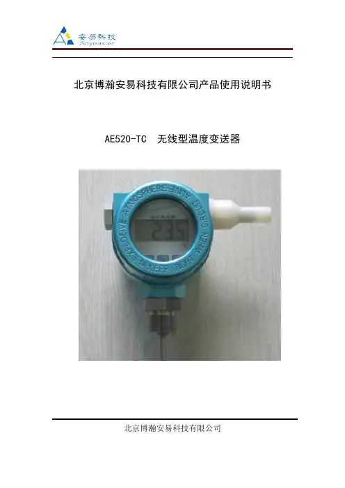
北京博瀚安易科技有限公司产品使用说明书AE520-TC无线型温度变送器北京博瀚安易科技有限公司一、概述本公司生产的AE520-T型无线温度变送器是一种超小型、性能优良、高精度的测温仪表。
它具有体积小,重量轻、使用安装方便的特点,将控制对象的温度参数变成电信号,传递给显示/调节面板,并对接收终端发送无线信号,对系统实行检测、调节和控制。
可直接安装在一般工业热电阻、热电偶的接线盒内,与现场传感元件构成一体化结构。
这样不仅节省了补偿导线和电缆,而且减少了信号传递失真和干扰,从而获的了高精度的测量结果。
通常和无线中继、接收终端、通信串口、电子计算机等配套使用,输出无线信号。
直接测量各种生产过程中的-100℃-800℃范围内液体、蒸汽和气体介质以及固体表面温度。
无线型温度变送器无线收发数据,通常和无线中继、接收终端、通信串口、电子计算机等配套使用,输出无线信号。
该产品的问世大大节省了现场安装布线成本,且使用极为方便。
二、特点�技术咨询QQ:583367295�带显示,电池供电,输出无线信号。
�精度高、抗干扰、免维护。
�带两键操作,可现场标定,数据由单片机处理,稳定性高。
�冷端温度自动补偿,非线性校正电路。
�具有防震、防潮、防热、防有害气体的功能。
�适用范围广,可应用于化工、冶金、石油、电力、水处理、制药、食品等自动化行业。
三、技术指标�传感器:PT100传感器�供电电压:电池供电,1-1.5年寿命�输出:无线数据传输�显示极限环境温度:-40℃~+85℃�环境湿度:5%-95%,无结露�振动:≤10g,f≤55Hz,振幅≤0.5mm�测量范围:-100℃~+500℃�精度:±0.5%�线性:±0.5%�外壳等级:IP65�发射频率:433MHz�自身增益:0-20db�通信距离:100米�连接螺纹:M20×1.5(可定做)四、安装结构一般规定变送器采用现场安装式结构,具有一定的防潮、防尘密封功能。
江森BAS技术方案
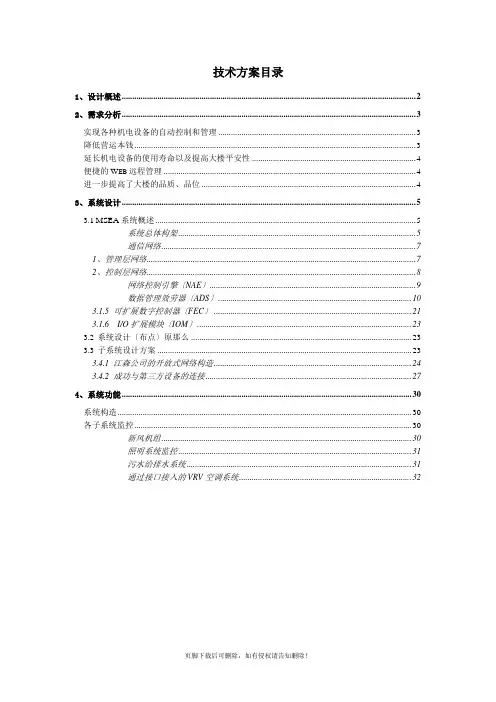
技术方案目录1、设计概述 (2)2、需求分析 (3)实现各种机电设备的自动控制和管理 (3)降低营运本钱 (3)延长机电设备的使用寿命以及提高大楼平安性 (4)便捷的W EB远程管理 (4)进一步提高了大楼的品质、品位 (4)3、系统设计 (5)3.1MSEA系统概述 (5)系统总体构架 (5)通信网络 (7)1、管理层网络 (7)2、控制层网络 (8)网络控制引擎〔NAE〕 (9)数据管理效劳器〔ADS〕 (10)3.1.5 可扩展数字控制器〔FEC〕 (21)3.1.6 I/O扩展模块〔IOM〕 (23)3.2系统设计〔布点〕原那么 (23)3.3子系统设计方案 (23)3.4.1 江森公司的开放式网络构造 (24)3.4.2 成功与第三方设备的连接 (27)4、系统功能 (30)系统构造 (30)各子系统监控 (30)新风机组 (30)照明系统监控 (31)污水给排水系统 (31)通过接口接入的VRV空调系统 (32)建筑设备管理系统〔BAS〕技术方案1、设计概述本工程楼宇设备监控系统是采用计算机及其网络技术、自动控制技术和通信技术组成的高度自动化的综合管理系统,它确保本工程成为具有最正确工作与生活环境、设备高效运行、整体节能效果最正确,而且平安的场所。
根据工程要求及特点,本工程设置一套完整的BAS系统,其中BAS中央工作站设置于消控中心内。
楼宇设备监控系统通过数据管理效劳器〔ADS〕、网络控制引擎〔NAE〕、现场型直接数字控制器〔DDC〕、对相关机电设备进展监控。
本工程BAS系统监控的内容主要包括:1、新风空调系统监控〔DDC〕2、照明系统3、给排水系统4、VRV空调集成系统BAS通过优化控制提高管理水平,到达节约能源和运行本钱,并能方便地实现物业管理自动化。
整个工程楼宇设备监控系统设计成一套完整的分布式集散控制系统,它采用标准化局域网技术和众多子系统集成技术实施对楼内所有实时监控系统的集成监控、联动和管理,系统既可相对独立运转,又可联合成为一个有机整体,对不同工作站及现场控制器的控制权限的设定,由网络管理效劳器完成。
BAS40-05中文资料
.30 (7.5) .12 (3)
.04 (1)
.08 (2) .04 (1) .08 (2)
.59 (15) .47 (12)
.03 (0.8)
0.2 (5)
.06 (1.5) .20 (5.1)
Dimensions in inches (millimeters)
Layout for RthJA test Thickness: Fiberglass 0.059 in (1.5 mm) Copper leads 0.012 in (0.3 mm)
1)
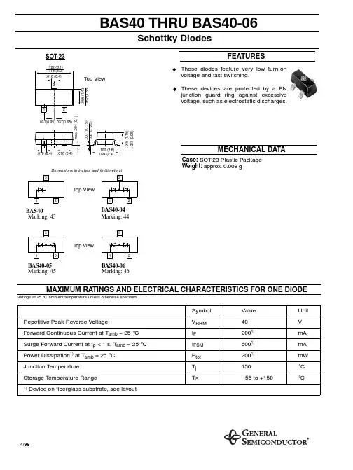
Value 40 2001) 6001) 2001) 150 –55 to +150
Unit V mA mA mW °C °C
VRRM IF IFSM Ptot Tj TS
Device on fiberglass substrate, see layout
4/98
元器件交易网
元器件交易网
BAS40 THRU BAS40-06
Schottky Diodes
SOT-23
.122 (3.1) .118 (3.0) .016 (0.4) 3
FEATURES ♦ These diodes feature very low turn-on
Top View
BAS40 THRU BAS40-06
ELECTRICAL CHARACTERISTICS
Ratings for one diode at 25 °C ambient temperature unless otherwise specified
Symbol Reverse Breakdown Voltage Tested with 10 µA Pulses Leakage Current Pulse Test tp < 300 µs at VR = 30 V Forward Voltage Pulse Test tp < 300 µs at IF = 1 mA at IF = 40 mA Capacitance at VR = 0 V, f = 1 MHz Reverse Recovery Time from IF = 10 mA through IR = 10 mA to IR = 1 mA Thermal Resistance Junction to Ambient Air
深川变频S280系列防爆变频器机芯说明书
S280系列防爆变频器机芯使用说明书资料版本 V1.1归档日期 2022-08-30企业标准: Q/913703SSC002-2019山东深川变频科技股份有限公司为客户提供全方位的技术支持,用户可与就近的山东深川变频科技股份有限公司办事处或客户服中心联系,也可直接与制造商联系。
版权所有,保留一切权利。
内容如有改动,恕不另行通知。
总部:山东深川变频科技股份有限公司客户热线:400-812-8821技术支持:400-812-6621质量反馈:400-812-0778投 诉:400-812-6125网 址:目录S280系列防爆变频器机芯说明书目 录第1章 安全及注意事项 (1)1.1 安全事项 (1)1.2 注意事项 (1)第2章 技术指标及选型 (2)2.1 命名规则 (2)2.2 铭牌 (2)2.3 型号与技术参数 (2)2.4 技术规范 (3)2.5 S280‐FB系列厂用防爆变频器通用机芯产品外形图、安装孔位尺寸 (4)2.6 S280‐RG系列中压防爆变频器热管机芯产品外形图、安装孔位尺寸 (11)2.7 键盘的外形尺寸 (12)2.8 制动组件选型推荐 (13)第3章 电气安装 (14)3.1 外围电气元件选型指导 (14)3.2 主回路端子及接线 (15)第4章 键盘操作与显示 (18)第5章 功能参数简表 (20)第6章 重点功能参数详解 (40)第7章 通讯协议 (48)第8章 故障检查与排除 (51)8.1 故障信息与排除方法 (51)8.2 常见故障及其处理方法 (53)S280系列防爆变频器机芯说明书第1章安全及注意事项第1章 安全及注意事项1.1 安全事项1、应由电气专业技术人员安装、调试变频器,否则有触电危险!2、接线前请确认电源处于关断状态,否则有触电危险!3、接地端子必须可靠接地,接地电阻应小于0.1Ω!4、不能将输入电源连到输出端U、V、W,否则引起变频器损坏!5、确保配线导线线径符合技术标准,否则可能发生事故!6、变频器无须进行耐压测试,出厂时产品此项已做过测试,否则可能引起事故!7、上电后不要触摸变频器端子(含控制端子),否则有触电危险!8、若要进行参数自学习,请注意电机旋转中伤人的危险,否则可能引起事故!9、不要采用接触器通断的方式来控制变频器的启停,否则引起设备损坏!10、断开电源后因滤波电容上仍然有高压,所以不能马上对变频器进行维修或保养,必须等待5分钟以上后用万用表测母线电压((+)和(-)之间的电压)不超过36V才可进行。
BASF Naphthamax II 催化剂
安全技术说明书页: 1/10 巴斯夫安全技术说明书日期 / 修订: 20.12.2011版本: 3.0产品: BASF NAPHTHAMAX II(30502802/SDS_GEN_CN/ZH)印刷日期 21.12.20111. 物质/制剂及公司信息BASF NAPHTHAMAX II推荐用途和限制用途: 化学品公司:巴斯夫应用化工有限公司中国 上海浦东江心沙路300号邮政编码 200137电话: +86 21 38655265传真号: +86 21 38655268E-mail地址: ximei.long@紧急联络信息:巴斯夫紧急热线中心(中国)电话: +86 21 5861-1199Company:BASF Auxiliary Chemicals Co., Ltd 300 Jiang Xin Sha RoadPu Dong Shanghai 200137, CHINA Telephone: +86 21 38655265 Telefax number: +86 21 38655268E-mail address: ximei.long@ Emergency information:Emergency Call Center (China): Telephone: +86 21 5861-11992. 危险性识别纯物质和混合物的分类:根据 GHS 标准,该产品不需要进行分类。
标签要素和警示性说明:根据GHS标准,该产品不需要添加危险警示标签其它危害但是不至于归入分类:注意有关存储和操作的规定或注解,无已知特殊危害。
巴斯夫安全技术说明书日期 / 修订: 20.12.2011版本: 3.0产品: BASF NAPHTHAMAX II(30502802/SDS_GEN_CN/ZH)印刷日期 21.12.20113. 成分/组分信息化学性质: 混合物催化剂制备基于:金属氧化物, 无机金属盐危险组分Cerium oxide (CeO2)含量 (W/W): >=0% - <7%CAS No.: 1306-38-3Acute Tox.: 分类5 (皮肤接触)magnesium oxide含量 (W/W): >=0.3% - <7%CAS No.: 1309-48-4Acute Tox.: 分类5 (口服)Praseodymium oxide (Pr6O11)含量 (W/W): >=0% - <7% CAS No.: 12037-29-5Aquatic Acute: 分类1 Aquatic Chronic: 分类1 M-系数 急性: 1M-系数 慢性: 1Samarium oxide (Sm2O3)含量 (W/W): >=0.3% - <1% CAS No.: 12060-58-1Aquatic Acute: 分类1 Aquatic Chronic: 分类1 M-系数 急性: 10M-系数 慢性: 10Gadolinium oxide (Gd2O3)含量 (W/W): >=0% - <7% CAS No.: 12064-62-9Aquatic Acute: 分类1 Aquatic Chronic: 分类1 M-系数 急性: 1M-系数 慢性: 1Neodymium oxide (Nd2O3)巴斯夫安全技术说明书日期 / 修订: 20.12.2011版本: 3.0产品: BASF NAPHTHAMAX II(30502802/SDS_GEN_CN/ZH)印刷日期 21.12.2011含量 (W/W): >=0% - <7% CAS No.: 1313-97-9Aquatic Acute: 分类1 Aquatic Chronic: 分类1 M-系数 急性: 10M-系数 慢性: 10Lanthanum (III) oxide (calcined)含量 (W/W): >=3% - <7%CAS No.: 1312-81-8Aquatic Chronic: 分类44. 急救措施一般建议:脱掉受污染的衣物。
Giant520称重模块用户手册
-6-
N,8,1(9600bps,无校验,8 个数据位,一个停止位)。 · 第 9 位,第 10 位处于其他状态时为运行模式。此时如果拨码开关的第 1-8 位全部=OFF,模块的 Modbus
地址由内部寄存器决定。如果拨码开关的第 1-8 位有任意一个不为 OFF,模块的 Modbus 地址由内拨码 开关决定。通信参数(波特率,校验位,停止位,通信协议等)在运行模式时均由内部寄存器设置决 定。
拨码开关 (1) 拨码开关 SW2
拨码开关 SW2 是一个 10 位的拨码开关。第 1-8 位用于设置模块的 modbus 地址;第 9,10 位用于设置 模块的状态。 · 第 9 位=OFF,第 10 位=ON 时为设置模式。此时模块的 Modbus 地址为固定为 0,通信参数固定为:9600,
大连哲勤科技有限公司 联系电话: 0411-66831953 13795113856 传真: 0411-39855398 网址: 邮件: infwin@ QQ:617165508
Giant520称重模块用户手册
大连哲勤科技有限公司 联系电话: 0411-66831953 13795113856 传真: 0411-39855398 网址: 邮件: infwin@ QQ:617165508
7
BIT1 OFF OFF ON ON …… ON OFF OFF …… ON ON
8
BIT0 OFF ON OFF ON …… ON OFF ON …… OFF ON
第 9,10 位用于设置模块的运行状态。具体如下: 拨码开关序号
0 1 2 3
9 OFF OFF ON ON
10 OFF ON OFF ON
大连哲勤科技有限公司 联系电话: 0411-66831953 13795113856 传真: 0411-39855398 网址: 邮件: infwin@ QQ:617165508
火灾报警联动控制系统产品手册
尊敬的用户:西安西核彩桥实业科技有限公司地处西安市高新技术开发区,是专业生产火灾报警联动控制系统的高新技术企业,是中美合资西安盛赛尔电子有限公司(systemsensor)的紧密型合作伙伴。
公司自主研发的CH8000系列智能火灾报警控制系统,全面采用美国盛赛尔公司(systemsensor)的设计理念、先进技术、通讯协议、制造工艺,与国际火警行业的先进技术同步,该系统全面兼容盛赛尔公司生产的智能型、常规型、特殊型产品,具有工作稳定、扩展性强、容量大、网络化等特点。
公司拥有优秀的团队、先进的设备、超前的理念,遍及全国的销售服务网络,产品广泛应用于石油、化工、电信、移动、钢铁等国家重点行业和大型楼宇场馆,以可靠的产品,优质的服务,诚信的文化赢得用户的满意。
公司将和全体销售服务商一起为用户竭诚服务,以我卓越科技,护航您美好未来。
目录1、JTY-LZ-ZM991智能离子感烟火灾探测器2、JTY-GD-ZM992智能光电感烟火灾探测器3、JTW-BD-ZM995智能感温火灾探测器4、JTY-GD-882光电感烟火灾探测器5、JTW-BD-885感温火灾探测器6、JTYJ-GD-2630/B 独立式感烟火灾探测报警器7、JTYJ-GD-2690/B 独立式感烟火灾探测报警器8、BAEM1224S型红外光束感烟火灾探测器9、AEC2361a 可燃气体探测报警器10、AEC2371a 可燃气体探测报警器11、J-SAP-M-SB8304 编址手动火灾报警按钮12、J-SAP-M-SB8304/H 编址消火栓报警按钮13、SM8301 输入模块14、KM8302 输入/输出模块15、KM8302B 切换模块16、DB8307 总线短路保护器17、M902M 探测器接口模块18、SG8306A 编址声光警报器19、ZH8310A 现场转换盒20、SSM24-6 警铃21、SG8306 声光警报器22、CH8504 放气指示灯23、CH8505 紧急启停按钮24、CH8507 手/自动转换盒25、CH8316/20/48/72 路接线端子箱26、CH8907/6/12/20模块箱27、FS-100 火灾显示盘28、CH8605 多线联动控制盘29、CH8601 总线手动控制盘30、JB-QB-CH8000 火灾报警控制器(联动型)31、JB-QB-CH8800 火灾报警控制器(联动型)32、JB-QB-CH8000/S 火灾报警控制器33、JB-MH-CH8500 气体灭火控制器34、JB-QB-CH8800 气体灭火控制器35、CH8909 CRT火灾彩色平面图形显示系统36、GB9242 消防广播主机37、DH9251 多线火警电话主机38、DH9261 总线制火警电话主机39、CH9200 壁挂广播通讯柜1、JTY-LZ-ZM991智能离子感烟火灾探测器功能描述及技术指标◆适用于发生火灾后产生大量的烟和少量热的场所,如宾馆、饭店、办公楼、机房、医院、学校等各种室内场所。
KBSGZY移变说明书
目 录前言 (III)1.概述 (1)2.技术数据 (2)3.结构特征 (11)4.安装与调试 (14)5.移动变电站操作 (15)6.故障分析与排除 (17)7.维修与防护 (17)8.运输与贮存 (18)9.订货须知 (18)附1:电气原理图附2:产品质量信息反馈单前 言本说明书按照GB 9969.1-1998工业产品使用说明书 总则 进行编制。
KBSGZY系列矿用隔爆型移动变电站(以下简称移动变电站)系列产品性能参数符合国家标准GB 3836.1~3-2000爆炸性气体环境电气设备和GB 8286-2005矿用隔爆型移动变电站的要求,符合电光防爆电气(宿州)有限公司企业标准Q/DG 02-2007矿用隔爆型移动变电站的要求。
警告:本产品属于高压设备,危险!用户在使用时必须按说明书要求操作,严禁带电开盖,严禁损伤隔爆面!使用前请认真阅读使用说明书!1.概述1.1产品性能和适用范围:KBSGZY系列矿用隔爆型移动变电站采用高品质的美国杜邦NOMEX®绝缘材料包封技术。
高、低压线圈经VPI特殊真空压力浸渍H级无溶剂漆,再经高温烘焙固化,保证了线圈的电气绝缘强度和机械强度。
铁心采用优质高导磁冷扎硅钢片,45℃全斜接缝、无冲孔,极大的提高了整个变压器的性能。
本系列产品适用于有甲烷混合气体和煤尘,且有爆炸危险的矿井中,将一次电压6kV、10kV电源转换成400(380)V、693(660)V、1200(1140)V、3450(3300)V煤矿井下所需的低压电源,专供井下电力输送和做综合机械化采煤电源之用。
1.2使用条件:a)海拔不超过1000m;b)环境温度:最高气温40℃,最热月平均温度30℃,最高年平均温度20℃,最低气温-5℃;c)空气相对湿度:不大于95﹪(﹢25℃时);d)在有甲烷混合气体和煤尘,且有爆炸危险的矿井中;e)无强烈颠簸、震动和与垂直面的斜度不超过15°的环境;f)无足以腐蚀金属和破坏绝缘的气体和蒸汽;g)无滴水的场所;h)电源电压的波形近似于正弦波;i)三相电源电压近似对称。
- 1、下载文档前请自行甄别文档内容的完整性,平台不提供额外的编辑、内容补充、找答案等附加服务。
- 2、"仅部分预览"的文档,不可在线预览部分如存在完整性等问题,可反馈申请退款(可完整预览的文档不适用该条件!)。
- 3、如文档侵犯您的权益,请联系客服反馈,我们会尽快为您处理(人工客服工作时间:9:00-18:30)。
BAS520-02VDocument Number 85846Rev. 1.2, 29-Jun-05Vishay Semiconductors1Small Signal Schottky DiodeFeatures•These diodes feature very low turn-on voltage and fast switching.•These devices are protected by a PN junction guard ring against excessive voltage, such as electrostatic discharges. •Space saving SOD-523 package •Lead (Pb)-free component •Component in accordance toRoHS 2002/95/EC and WEEE 2002/96/ECMechanical DataCase: SOD-523 Plastic caseMolding Compound Flammability Rating: UL 94 V-0Terminals: High temperature soldering guaranteed: 260°C/10 sec. at terminals Weight: approx. 1.6 mgPackaging Codes/Options:GS18 / 10 k per 13" reel (8 mm tape), 10 k/box GS08 / 3 k per 7" reel (8 mm tape), 15 k/boxParts TableAbsolute Maximum RatingsT amb = 25°C, unless otherwise specifiedThermal CharacteristicsT amb = 25°C, unless otherwise specifiedPartOrdering codeMarkingRemarksBAS520-02VBAS520-02V-GS18 or BAS520-02V-GS08TTape and ReelParameterT est conditionSymbol Value Unit Repetitive peak reverse voltage V RRM 30V Forward continuous current T amb = 25°C I F 200mA Power dissipationT amb = 25°CP tot200mWParameterT est conditionSymbol Value Unit Junction soldering point R thJS 100K/W Junction temperature T j 125°C Storage temperature rangeT S- 55 to +125°C 2Document Number 85846Rev. 1.2, 29-Jun-05BAS520-02VVishay Semiconductors Electrical CharacteristicsT amb = 25°C, unless otherwise specifiedTypical Characteristics (Tamb = 25 °C unless otherwise specified)ParameterTest conditionSymbol Min Typ.MaxUnit Reverse breakdown voltage I R = 1 µA (pulsed)V (BR)30V Leakage current Pulse test V R = 30 V , t p < 300 µs I R 0.51µA Forward voltagePulse test t p < 300 µs, I F = 1.0 mAV F 320mV Pulse test t p < 300 µs, I F = 200 mA,V F 600mV Diode capacitance V R = 0 V , f = 1 MHz C tot 2530pF Reverse recovery timeI F = 10 mA, I R = 10 mA, I rr = 1 mA, R L = 100 Ωt rr10nsFigure 1. Typical Capacitance vs. Reverse Voltage 0510*******481216202428323618960V R -Reverse V oltage (V)C -D i o d e C a p a c i t a n c e (p F )D18961100100.10.0110001F I -F o r w a r d C u r r e n t (m A )Figure 3. Typical Reverse Voltage vs. Reverse Current18962I R -Reverse Current (µA )BAS520-02VDocument Number 85846Rev. 1.2, 29-Jun-05Vishay Semiconductors3Package Dimensions in mm (Inches) 4Document Number 85846Rev. 1.2, 29-Jun-05BAS520-02VVishay SemiconductorsOzone Depleting Substances Policy StatementIt is the policy of Vishay Semiconductor GmbH to1.Meet all present and future national and international statutory requirements.2.Regularly and continuously improve the performance of our products, processes, distribution and operatingsystems with respect to their impact on the health and safety of our employees and the public, as well as their impact on the environment.It is particular concern to control or eliminate releases of those substances into the atmosphere which are known as ozone depleting substances (ODSs).The Montreal Protocol (1987) and its London Amendments (1990) intend to severely restrict the use of ODSs and forbid their use within the next ten years. Various national and international initiatives are pressing for an earlier ban on these substances.Vishay Semiconductor GmbH has been able to use its policy of continuous improvements to eliminate the use of ODSs listed in the following documents.1.Annex A, B and list of transitional substances of the Montreal Protocol and the London Amendmentsrespectively2.Class I and II ozone depleting substances in the Clean Air Act Amendments of 1990 by the EnvironmentalProtection Agency (EPA) in the USA3.Council Decision 88/540/EEC and 91/690/EEC Annex A, B and C (transitional substances) respectively. Vishay Semiconductor GmbH can certify that our semiconductors are not manufactured with ozone depleting substances and do not contain such substances.We reserve the right to make changes to improve technical designand may do so without further notice.Parameters can vary in different applications. All operating parameters must be validated for each customer application by the customer. Should the buyer use Vishay Semiconductors products for any unintended or unauthorized application, the buyer shall indemnify Vishay Semiconductors against all claims, costs, damages, and expenses, arising out of, directly or indirectly, any claim of personal damage, injury or death associated with such unintended or unauthorized use.Vishay Semiconductor GmbH, P.O.B. 3535, D-74025 Heilbronn, GermanyDocument Number: 91000Revision: 18-Jul-081DisclaimerLegal Disclaimer NoticeVishayAll product specifications and data are subject to change without notice.Vishay Intertechnology, Inc., its affiliates, agents, and employees, and all persons acting on its or their behalf (collectively, “Vishay”), disclaim any and all liability for any errors, inaccuracies or incompleteness contained herein or in any other disclosure relating to any product.Vishay disclaims any and all liability arising out of the use or application of any product described herein or of any information provided herein to the maximum extent permitted by law. The product specifications do not expand or otherwise modify Vishay’s terms and conditions of purchase, including but not limited to the warranty expressed therein, which apply to these products.No license, express or implied, by estoppel or otherwise, to any intellectual property rights is granted by this document or by any conduct of Vishay.The products shown herein are not designed for use in medical, life-saving, or life-sustaining applications unless otherwise expressly indicated. Customers using or selling Vishay products not expressly indicated for use in such applications do so entirely at their own risk and agree to fully indemnify Vishay for any damages arising or resulting from such use or sale. Please contact authorized Vishay personnel to obtain written terms and conditions regarding products designed for such applications.Product names and markings noted herein may be trademarks of their respective owners.元器件交易网。