Numerical simulation on the impacting and comminuting of coal based on LS-DYNA
numerical analysis method

numerical analysis methodNumerical analysis methods are techniques used to approximate the solutions of mathematical problems that cannot be solved analytically. These methods involve the use of numerical algorithms and computers to obtain approximate solutions. Here are some common numerical analysis methods:1.Interpolation:Interpolation is a method used to estimate the value of a function at a point based on the known values of the function at other points. There are various types of interpolation, such as linear interpolation, polynomial interpolation, and spline interpolation.2.Integration:Integration is the process of calculating the area under a curve. Numerical integration methodsapproximate the integral by dividing the region into small subintervals and calculating the area of each subinterval.3 Differentiation:Differentiation is the process of calculating the slope ofa curve at a point. Numerical differentiation methodsapproximate the derivative by calculating the slope of the line connecting two points on the curve.4.ODEs and PDEs:Ordinary differential equations (ODEs) and partial differential equations (PDEs) are equations that describe the evolution of a system over time or in multiple dimensions. Numerical methods are used to solve these equations, such as Euler's method, Runge-Kutta method, and finite element method.5.Simulation:Simulation is a technique used to model the behavior of a system or process. Numerical simulation methods use mathematical models and numerical algorithms to simulate the behavior of the system and predict its output.6Optimization:Optimization is the process of finding the best solution to a problem. Numerical optimization methods use algorithms such as gradient descent, Newton's method, and genetic algorithms to find the最优 solution.These are just some examples of numerical analysis methods. Numerical analysis is a broad field that encompasses many other techniques and applications. The choice of numerical method depends on the specific problem being solved and the desiredaccuracy and efficiency of the solution.。
海上作战体系仿真建模技术
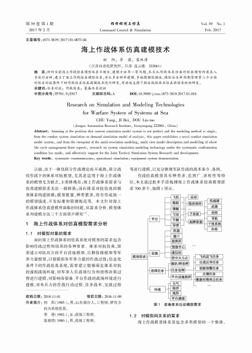
第39卷第1期2017年2月指輝控制与仿真C o m m a n d C o n tro l &S im u la tio nYol. 39 No. 1Feb.2017文章编号:1673-3819( 2017) 01-0073-04海上作战体系仿真建模技术初阳,季蓓,窦林涛(江苏自动化研究所,江苏连云港222061)摘要:针对当前海上作战仿真模型体系不健全、建模方法单一等问题,本文从作战体系仿真对仿真模型的需求入 手进行分析,建立了海上作战仿真模型体系,并从多分辨率建模、多视图模型描述、模型全生命周期管理等三个方面 对体系对抗条件下的作战体系仿真建模技术进行研究,有效地支持了联合战役战术仿真推演系统的研发。
关键词:体系对抗;作战仿真;装备体系论证中图分类号:T P391. 9;E917 文献标志码:A D0I:10.3969/j.issn.1673-3819.2017.01.016Research on Simulation and Modeling Technologiesfor Warfare System of Systems at SeaCHU Yang,JI B e i,DOU Lin-tao(Jiangsu A utom ation Research In s titu te,Lianyungang 222061,C h in a)A b s t r a c t:A im m in g at the problem that cu rre n t sim u la tio n m odel system is not perfect and the m odeling m ethod is s in g le,fro m the com bat system s im u la tio n on dem and sim u la tio n m odel of a n a lysis,th is paper establishes a naval com bat sim u la tio n m odel system,and fro m the view po int of the m u lti-re s o lu tio n m o d e lin g,m u lti view m odel d e scrip tio n and m o d e llin g of whole life cycle management three aspects,research on system s im u la tio n m odeling technology u n der the system atic confrontation co n d itio n has m a d e,and e ffe ctive ly support fo r the Jo in t T a ctica l S im ulatio n System Research and developm ent.K e y w o r d s:system atic counterm easure;op erational s im u la tio n;equipm ent system dem onstration目前,由于一体化联合作战理论尚不成熟,联合战役作战下的体系对抗模型,尤其是适用于海上作战体系的模型尤为缺乏,主要体现在:海上作战体系需求与仿真建模需求无法一致转换;面向体系对抗仿真的模型体系构建困难;模型数量、种类繁多,没有形成统一的模型描述、开发标准和管理规范等。
impact造句

impact造句1、air impact moulding machine.2、Brinell impact hardness tester.3、impact (evaluation) report.4、impact cell mill.5、4.2.3.1 impact identification.6、Impact heat distortion temperature and low; temperature impact strength.7、That should lessen its impact.8、His impact reflected anonymous dedication.9、Cases having great impact nationwide.10、The impact has been lethal.11、Might they impact worker morale?12、The impact of "Griffinization" is twofold.13、Will implementing reliability negatively impact performance?14、Measuring impact in philanthropy is not easy.15、The word "Ilousy" has lost its impact.16、The impact on Indian society is grim.17、Equivalent Static Force of Ship Impact to Bridge Based on impact Numeric Simulati on-Fundamental Formula.18、It can impact on the relationship and that will impact on your children.19、Eco-tax Impact on Economic Life: A dynamic CGE analysis of the impact of Eco-tax.20、The effects of impact Angle, particle velocity, erodent size and impact time were de monstrated.21、Among the five steps the impact identification, impact prediction and impact evalu ation are most important. For each step there are different methods and considerations.22、Impact detecting resistors (141), (143) of an impact detecting circuit (104) detectac ounter electromotive force of a step motor (105) generated due to an impact.23、The effects of impact energy and impact times on the green density, the maximal impact force and the withdraw force of specimen were investigated.24、Don't try to quantify the impact of each individual kaizen.25、Where should we look for the impact of kaizen?26、Every kind of life style can impact on our body.27、DOI and CrossRef and their impact on scientific periodical publishing.。
翻译原文
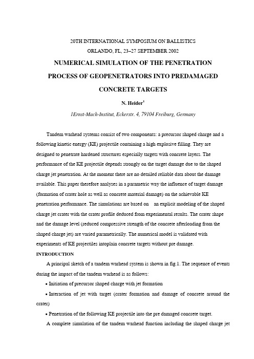
20TH INTERNATIONAL SYMPOSIUM ON BALLISTICSORLANDO, FL, 23–27 SEPTEMBER 2002NUMERICAL SIMULATION OF THE PENETRATIONPROCESS OF GEOPENETRATORS INTO PREDAMAGEDCONCRETE TARGETSN. Heider11Ernst-Mach-Institut, Eckerstr. 4, 79104 Freiburg, GermanyTandem warhead systems consist of two components: a precursor shaped charge and a following kinetic energy (KE) projectile containing a high explosive filling. They are designed to penetrate hardened structures especially targets with concrete layers. The performance of the KE projectile depends strongly on the target damage due to the shaped charge jet penetration. At the moment there are no detailed reliable data about the damage available. This paper therefore analyses in a parametric way the influence of target damage (formation of crater hole as well as concrete material damage) on the achievable KE penetration performance. The simulations are based on an explicit modeling of the shaped charge jet crater with the crater profile deduced from experimental results. The crater shape and the damage level (reduced compressive strength of the concrete afterloading from the shaped charge jet) are varied parametrically. The numerical model is validated with experiments of KE projectiles intoplain concrete targets without pre damage. INTRODUCTIONA principal sketch of a tandem warhead system is shown in fig.1. The sequence of events during the impact of the tandem warhead is as follows:∙ Initiation of precursor shaped charge with jet formation∙ Interaction of jet with target (crater formation and damage of concrete around the crater)∙ Penetration of the following KE projectile into the pre damaged concrete target.A complete simulation of the tandem warhead function including the shaped charge jetpenetration is given in [1]. The theoretical description of the performance of the two tandem warhead components as a single weapon is already very good (within numerical as well as analytical modeling). Some uncertainties still exist for the tandem system especially concerning the interaction of the KE projectile with the damaged target. The analytical and empirical modeling of the tandem system therefore requires some better understanding of the target damage and its influence on the time history of the KE projectile penetration process. Due to the lack of detailed experimental and theoretical data on the damage distribution within the target it seems a reasonable approach to analyze the penetration process with the help of parametric variations of the relevant parameters describing the crater and the degree of damage in the concrete target material. This method allows the separate investigation of the influence of these physical parameters on the penetration depth of the KE projectile and a detailed understanding of the involved processes.Fig.1 Components of tandem warhead system Fig.2 Parameterization of carter ProfileEXPERIMENTAL BASISThe simulation model is based on experimental results of concrete penetration with shaped charge jets and KE projectiles.The explicit modeling of the damaged concrete target requires information about typical crater profiles created by the impact of the shaped charge jet. The crater profiles are taken from experiments where shaped charges were fired against concrete targets at a stand off of 3 calibers. The crater profiles are not very sensitive to stand off as soon as the maximum penetration depth as a function of stand off is reached. Even at high stand off values of 20calibers the crater profiles are still similar to the corresponding ones at 3 calibers. The tests have been performed with 80 mm caliber charges with aluminum liners and point initiation. Typical crater profiles have the following characteristics:Biconical profile (see fig.2)Spall crater at shaped charge jet impact surfaceErosion crater reaching to the final depth.The explicitly modeled crater profiles are derived from these data.The KE projectile penetration into undamaged concrete targets was used as avalidation case for the simulation model including the concrete material description.The following penetrator design was used:Caliber 60mmLength 508mmMass 6039gThe target consisted of two concrete blocks of diameter 96cm, length 1m and a steel casing. The concrete compressive strength was 35N/mm2 . The experimental results were (see [2] and [3] for experimental details and interpretation of penetration depth within cavity expansion theory):Impactvelocity 509m/secPenetration depth 114.5cmFig.3 shows the front and rear side of the target after impact of the KE projectile.Fig.3 KE projectile impact test: front and rear side of concrete target The corresponding results from the simulation are shown in fig.4 with the configurationat the time of impact and after the penetrator came to rest. The calculated penetration depth is 119 cm and agrees very well the experimental value of 114.5cm.Fig.4 Simulation: KE penetrator at impact and at end of penetrationSIMULATION MODELThe simulation model consists of the damaged target and the KE penetrator. Theperformance of the shaped charge jet is not explicitly modeled. Instead the crater profile andthe damage area around the crater are modeled explicitly. The simulation model used forthis application is based on the erosion crater because the radius of the spall crater issignificantly bigger than the radius of the KE projectile and thus has no influence on the KEprojectile penetration. The crater used in the simulations is thus characterized by twodiameters corresponding to target surface and the final penetration depth. These twoparameters can be varied to study the influence of crater diameter on the penetration process.As no date are available about the damage produced in the concrete target due to thepenetration of the shaped charge jet, the damaged region around the crater and the amount ofstrength reduction are additional variation parameters. The damaged area was assumedcylindrical with a certain depth and radius and a constant degree of damage within this area.These are three further variation parameters.The presented model parameters are deduced from experiments if possible and in theother cases are varied in a range that seems to be reasonable and interesting for he physicalunderstanding.The simulation contains the three materials: original concrete target, damaged concretetarget and the high strength steel penetrator case. The high strength steel is described with aJohnson Cook model for the deviatoric strength behavior. Very important is the material description of concrete. For this purpose the RHT model, developed at EMI is used .Concrete has the following experimental material properties:∙ Tensile strength is 1/10 of compressive strength∙ Shear strength is pressure dependent∙ Damage development (failure surface depends on damage due to preloading)∙ Porosity and existence of micro cracks between mortar and aggregatesThe description of these phenomena requires a complex model for the characterization of concrete. The EMI RHT model includes the static as well as the dynamic range and thus can be used for the penetration processes of KE penetrators.The following gives a short summary of the main properties of the model:∙ Porous equation of state∙ Limit surfaces pressure dependent (elastic, failure and residual strength)∙ Limit surfaces depend on all 3 invariants of stress tensor∙ Strain rate effectsFig.5 shows the schematic location of the different limit surfaces in the stress space especially the change of the failure surface due to damage development. Damage occurs as soon as the failure surface in the stress space is reached during a loading process. In the uniaxial compression test damage occurs in the stress strain diagram in the region following the maximum compression stress. The material behavior is then characterized by macroscopic crack development. The following phenomena have to be described:∙ Reduction of the failure surface with increasing damage (material with a complete damage can not sustain any tensile stresses any more)∙ Reduction of elastic constantsIn the following the presented modeling parameters are varied and their influence on the KE penetration depth is analyzed.SIMULATION RESULTSThe simulation variants analyzed are shown in fig.6. The reference case is simulation 1 with the original undamaged concrete target. Varied is the crater profile (simulation 2 and 7)and the damaged area around the crater (spatial extend and damage level, simulations 3 to 6 and 8 to 12). In addition a simulation 13 was performed with a semi infinite target to get information about the influence of the target size on the penetration performance.Influence of the crater diameter: fig.7 shows the penetration depth of the KE projectile as a function of the crater radius on the impact surface. The penetration depth from the simulation in the undamaged target is 1198mm (the corresponding experimental value is 1145mm). Modeling of the eroded crater profile (without damage in the region around the crater) gives an increase to 1251mm (crater radius 11.2mm) or 1404mm (crater radius22.4mm). Small hole diameters (compared with the projectile diameter) lead only to a small increase of the performance of the penetrator. Only hole diameters approaching half of the penetrator caliber significantly increase the penetration depth.Influence of strength reduction: fig.8 shows the penetration depth as a function of time for several simulations. Here the reference configuration 1 is compared with the simulation 6 where the model shows only a strength reduction (from 35MPa for the original concrete to10MPa for damaged concrete) but no crater hole in the target. The penetration depth increases from 1198mm to 1377mm. The increase is nearly as high as for simulation 2 with the crater profile modeled (penetration depth for simulation 2 is 1404mm). The strength reduction with a spatial extension of 2 penetrator calibers around the impacting projectile thus leads already to a significant performance increase.Combination of crater profile and strength reduction: fig.8 contains the simulations 1,3 and 4. This corresponds to the situation where crater profile and strength reduction occur together. The penetration depth increases from 1198mm (reference case) to 1458mm (simulation 3 with small damage area) and finally to 1467mm (simulation 4 with bigger damage area). Comparison with the former results shows that the combined effect leads to a relatively small additional increase of penetration.Material damage or crater hole alone give already most of the achievable performance gain. The combination shows an overmatch for the simulated configuration. Variation of the damage level from 10MPa to 5MPa gives an additional penetration depth increase (simulation 4 - 1467mm compared with simulation 5 - 1490mm). It is important to note that there is no linear addition of the contributions fromdamage and crater hole to the total penetration. The whole target damage in front of the penetrator determines the performance independent by which effect it is caused. If there is already a significant damage due to eroded material an additional material damage has only minor influence. On the other hand material damage alone is sufficient to increase the penetration depth significantly.Fig.6 Simulated crater profiles and damaged target areasInfluence of spatial extension of damage zone: the radial as well as the axial extension of the damage zone is varied. For the axial extension the two values of 637mm and 1000mm were selected. The crater hole profile itself was not changed. The dependence of the penetration on the radial extension of the damaged area is shown in fig.9. There is a sort of plateau formation at a radial distance of around 2 projectile calibers with a penetration increase of around 250mm. The 2 significantly lower values at the radial distance at 50mm correspond to the axial damage extension of 637mm.This shows the importance of the radial as well as the axial extension of the damaged target regions on the penetration.Fig.5 Schematic representation of Fig.7 KE projectile penetration aslimit surfaces of concrete a function of crater radiusFig.8 Time history of KE Fig.9 KE projectile penetration asprojectile penetration a function of damage radius Influence of target dimension: a final simulation 13 was done which modeled a target with semi infinite extension (simulated with corresponding boundary conditions). The penetration is 1104mm and has to be compared with the value of 1198mm from the reference simulation 1. It gives an impression of the expected variation of performance of KE projectiles in real targets where different impact conditions are found. The decrease of penetration is due to the higher confinement and the reduced effects from the target boundaries.SUMMARYThe performance of the precursor shaped charge in a tandem warhead systems leads to a weakening of target (formation of crater hole and material damage). The development of engineering codes for the description of the tandem system requires a detailed understandingof the separated effects. Therefore a finite element model was developed that is based on experimental results and includes an explicit modeling of the crater profile and damaged region around the crater. The model allows the parametric analysis of the target weakening on the penetration of the KE projectile.Following conclusions can be drawn:∙ The penetration depth increase of the penetrator is not a linear combination of eroded crater and damage around the crater. In the analyzed parameter range both effects alone lead nearly to the final penetration depth.∙ Penetration increases slowly with crater diameter and reaches significant contributions at crater diameter larger than half of the penetrator caliber.∙ The damage area (radial and axial extend) influences the penetration depth with the effects being strongly pronounced when the damage area is significantly larger than the penetrator caliber.REFERENCES1. N. Heider, S. Hiermaier, Numerical Simulation of the Performance of Tandem Warheads,Proceedings of the 19th International Symposium on Ballistics, 807-815, 20012.N. Heider, U. Günther, Modern Geopenetrators and Relevant Revision of Concrete Penetration Models, Proceedings of the 5th International Symposium on Structures Under Shock and Impact (SUSI), 807-815, 19983.K. Kleinschnitger, C. Mayrhofer, E, Schmolinske, Modellversuche mitKE-Penetratoren gegen Betonziele, Internal EMI Report E 8/94, 19944.W. Riedel, Beton unter dynamischen Lasten Meso-und makromechanische Modelle und ihre Parameter, Dissertation Universität der Bundeswehr, 143-166, 2000。
平头弹撞击角度对2A12-T4铝合金板失效特性影响的数值模拟

平头弹撞击角度对2A12-T4铝合金板失效特性影响的数值模拟胡静;邓云飞;崔亚男;张银波【摘要】利用有限元软件ABAQUS建立模拟模型,开展38CrSi钢弹体撞击2A12-T4铝合金板数值模拟研究,分析撞击过程中弹体撞击角度对弹道姿态及靶体失效特性的影响.基于数值仿真和实验结果,分析靶体的失效特性,确立不同撞击条件下靶体主要失效模式的转变规律,以及由此对靶体抗撞击性能的影响.研究结果表明:弹体的弹道极限速度随其撞击角度的增大先减小后增大,弹道极限速度在撞击角度约为15°时达到最小值;弹体撞击角度对靶体失效模式存在很大影响,随着弹体撞击角度的增大,靶体主要失效模式由剪切破坏逐渐过渡到撕裂破坏,靶体的撕裂程度不断加剧;弹体初始撞击角度和速度对其在撞击过程中的弹道姿态存在影响,在弹道极限速度附近表现尤为显著.%A simulation model was established using finite element software ABAQUS,and the numerical simulations of 38CrSi steel projectile impacting 2A12-T4 aluminum alloy plates were conducted, then the influences of impact angles of projectile on the failure characteristics of target and ballistic attitude of projectile were analyzed.Based on numerical simulation and experimental results,the failure characteristics of the target were analyzed,the change laws of the dominant failure modes under different impact conditions,as well as the influences on the impact resistance of target because of that were established.The results show that with the increases of impact angles the ballistic limit velocity decreases,and then increases,and the ballistic limit reaches the minimum when the impact angle is about 15 degrees. In addition,the impact angle ofprojectile impacting greatly influences the failure mode of target,with the projectile angle increases,the dominant failure mode of target changes from shearing to tearing,and also increasing the degree of tearing the target.The initial impact angle and velocity of projectile have great influences on the trajectory attitude of the projectile during the impacts,especially in the vicinity of the ballistic limit velocity.【期刊名称】《中国机械工程》【年(卷),期】2018(029)009【总页数】6页(P1050-1054,1062)【关键词】撞击;2A12-T4铝合金板;平头弹体;失效模式【作者】胡静;邓云飞;崔亚男;张银波【作者单位】中国民航大学航空工程学院,天津,300300;中国民航大学航空工程学院,天津,300300;中国民航大学航空工程学院,天津,300300;中国民航大学航空工程学院,天津,300300【正文语种】中文【中图分类】O385;O3470 引言弹靶撞击属于经典的冲击动力学问题,撞击结果受到多种因素的影响,如弹靶材料力学性能、靶体结构、弹体几何形状、弹体撞击角度与速度等。
Experimental and numerical investigations on the influence o

can occur, e.g. either occasionally paired with an overload (mixed mode overload) or permanently in terms of a mixed mode block loading as a combination of normal and shear stresses. By means of this change, the lifetime is influenced as well. Only few investigations of such mixed mode loading change effects on the lifetime are described in the literature [e.g. 3–6]. Within the scope of this paper, firstly the influence of mixed mode loading changes in terms of mixed mode (Mode ICMode II) overloads and block loadings, which are interspersed into a Mode I baseline level loading, is experimentally investigated. Secondly, a detailed elastic– plastic finite element analysis of the fatigue crack growth after mixed mode overloads, which are interspersed into a Mode I baseline level loading, is presented in order to understand the mechanisms of the load interaction effects.
船舶结构碰撞试验及简化数值计算方法

本文网址:/cn/article/doi/10.19693/j.issn.1673-3185.03193期刊网址:引用格式:卢安格, 王子棠, 孔祥韶, 等. 船舶结构碰撞试验及简化数值计算方法[J]. 中国舰船研究, 2024, 19(2): 128–139.LU A G, WANG Z T, KONG X S, et al. Ship structure collision experiments and simplified numerical calculation meth-od[J]. Chinese Journal of Ship Research, 2024, 19(2): 128–139 (in Chinese).船舶结构碰撞试验及简化数值计算方法扫码阅读全文卢安格1,王子棠1,孔祥韶*1,李樱2,陈三桂2,吴卫国31 武汉理工大学 船海与能源动力工程学院,湖北 武汉 4300632 中国舰船研究设计中心,湖北 武汉 4300643 武汉理工大学 绿色智能江海直达船舶与邮轮游艇研究中心,湖北 武汉 430063摘 要:[目的]采用流固耦合计算方法虽能较好地模拟船舶碰撞过程,但计算时间较长,为此,提出一种简化的数值计算方法。
[方法]以某船的局部舱段为对象,开展多工况水上碰撞试验。
采用力传感器和基于高速摄影技术非接触测量的方法获得到碰撞力及碰撞船的运动时程数据,通过对碰撞接触力和加速度响应等数据进行分析,并针对试验过程开展任意拉格朗日−欧拉(ALE )流固耦合数值计算分析,提出将碰撞过程中水域对撞击船的影响简化为等效质量,将对被撞船的影响简化为等效阻力,以面力的形式作用于被撞船非撞击侧用以阻碍被撞船运动的简化方法,然后基于此简化方法开展不涉及水域与结构耦合过程的数值计算。
[结果]结果显示,采用简化计算方法得到的各工况的碰撞力峰值与试验值间的误差均在5%以内,且该方法所需要的计算时长远小于ALE 流固耦合算法。
包钢长材厂蓄热式加热炉数值模拟

包钢长材厂蓄热式加热炉数值模拟!刘中兴1冯猛1伍永福1张鹏1!2戈春刚2(1.内蒙古科技大学内蒙古自治区白云鄂博矿多金属资源综合利用重点实验室,2.包钢长材厂)摘要以包钢长材厂蓄热式加热炉为研究对象,利用A n sy s软件采用湍流模型、P- 1辐射模型等,模拟了采用交错燃烧组织方式加热炉内各物理场分布情况。
发现该种燃烧方式下,炉内流动涡流运动明显加强,有利于燃烧的混合和组织。
但出口附近的回流造成燃烧短路,高温烟气不易达到炉膛中心,易造成炉内温度不均匀,氧气浓度相对较高不利于钢坯生产,因此该平顶、平底炉型采用交错换向燃烧有待于进一步实践验证。
关键词蓄热式加热炉数值模拟物理场高温空气燃烧技术Numerical simulation on the long materitil factoryof Baogangd regenerative furnaceLiu Zhongxing1Feng Meng1Wu Yongfu1Zhang Peng1,2Ge Chungang2(1. Inner Mongolia University of Science and Technology,2.Long Material Factory of Baogang)Abstract The regenerative heating furnace of tlie long material factory was taken as the research obje c t,used the m odel of '- $ turbulence model and P -1radiation model using Ansys software,andsimulated the distribution of the physical field in the furnace with staggered combust is found that the flow vortex motion in the furnace is obviously enhanced under And it is also conducive to the mixing and organization of the combustion. But the reflow caused bycombustion short circuit near the exit. High temperature f lue gas is not easy to reach the center of thefurnace and cause t he furnace t uneven temperature distribution. Oxygen concentration is relativelyhigh,which is unfavorable to billet production. Therefore,the flat roof and flat hearth type adoptedstaggered reversing combustion need to be further verified.Keywords regenerative furnace numerical simulation physical field high temperature air combustion加热炉是工业加热的关键设备,广泛应用于 国民经济的各行各业。