涡流技术在球墨铸铁硬度检测中的应用
涡流探伤和硬度深度检测

17th World Conference on Nondestructive Testing, 25-28 Oct 2008, Shanghai, China Eddy Current Measurement of Case Hardened Depth of SteelComponentsJohn CUFFE 1, Haiyan SUN 2, Yuri PLOTNIKOV 2, Shridhar NATH 2,Aparna SHEILA-VADDE 31 GE Inspection Technologies, Lewistown, PA, USA, john.cuffe@2 GE Global Research, Niskayuna, NY, USA, sun@,plotnikov@, nath@3 GE John F Welch Technology Centre, Bangalore, India, aparna.vadde@ AbstractSteel components are often subjected to a hardening process in which the surface gets hardened in order to improve resistance to wear. This introduces a casehardened layer. Various steel components have different requirements for the case depth. It is necessary to develop a nondestructive tool to monitor case depth for quality control. The case hardening process produces changes in the microstructure. As a result, the electrical conductivity and magnetic permeability in the casehardened region are different from those in the substrate. This makes it possible to determine case depth using eddy current method. In this paper, multi-frequency eddy current and pulsed eddy current methods will be investigated to measure case hardened steel components. Results and recommendations will be provided showing comparison between measured and actual case depths.Keywords: case hardened steel, case depth, multi-frequency eddy current, pulsed eddy current1. IntroductionInduction hardening of steel components improves the resistance to wear by changing and microstructure of the surface region. The required depth of the casehardened layer varies depending on the purpose for which the component is needed. Monitoring case depth in steel components is critical for quality control of both new and remanufactured products. Usually, case depth is determined by measuring micro hardness profile in randomly selected samples. Sample preparation includes cutting and polishing in the areas of measurements. This method is time consuming and expensive. As a result it can be used on a small fraction of samples. A reliable non-destructive method is desired to improve efficiency of the measurements and monitor all the parts ran through the case hardening process. Different nondestructive methods have been investigated to measure hardness and case depth, such as ultrasonic wave[1], Barkhausen noise measurement[2] and eddy current [3].The case hardening procedure produces changes in the electrical conductivity and magnetic permeability of the steel in the case hardened region[4]. As the eddy current method is sensitive to these material properties, it is an expected candidate for the case depth estimation. An encircling coil was used to obtain the case depth of induction-hardened cylindrical rods using model-based approach, with case depths varying from 0.5mm – 2mm [2]. In this work, eddy current systems using pencil probe were developedto conduct measurements on induction hardened cylindrical samples with case depth varying from 1mm to 6mm. Localized measurement at different locations of the sample will be shown. Comparison between estimated and actual case depths will be provided.2. Samples and Systems2.1 Cylindrical induction hardened samplesTo investigate applicability of the eddy current technique, a set of samples with different case hardening depths was fabricated. All the samples are cylindrical rods, which are 100 mm long and 30 mm in diameter. There are 3 sets of samples (A, B and C), which are induction hardened with nominal case depth from 1 mm to 6 mm.2.2 Eddy current systemsA multi-frequency eddy current (MFEC) system and pulsed eddy current (PEC) system were developed for the experimental study. The MFEC system includes a function generator to generate the drive current in the eddy current probe, a lock-in amplifier to measure the probe response and a preamplifier to amplify probe signal. The lock-in amplifier has a frequency range from 1 mHz – 102.4 kHz. The function generator has a maximum output voltage of 10V. Gain of the signal preamplifier is adjustable with a single resistor. Fig.1 shows the diagram and picture for the MFEC system.experimental setup(b)Fig. 2. Block diagram of the PEC system for case depth measurements.The PEC includes a pulse generator that can produce drive pulses of variable width and amplitude, a 14-bit resolution analog-to-digital converter with a sampling rate up to 100 MS/s connected to an industrial computer and display (Fig. 2). A special program was developed to control data acquisition and process data in digital form. The pulse generator produces 5 ms long pulses of 40 V in magnitude with a repetition rate of 10 Hz. Transient responses 20 ms in length are received and digitized with a sampling rate of 100 kS/s.3. Probe DesignsVarious eddy current probes were designed and fabricated. Simulations were conducted by FEM software to optimize design and testing parameters. Parameters that were simulated include different probe types, number of turns, ferrite core, probe orientation and excitation frequency. As an example, Fig. 3 (a) below shows the FEM model for a circumferential probe. Fig. 3 (b) and (c) show the simulated eddy current field.A number of probes were fabricated by GE Inspection Technologies. Different probes were tested and compared. Results to-date shows that a 16mm reflection probeand a 20mm circumferential probe provide the best results.4. Experimental MeasurementA sample holder with curved slots on the top was made to hold the cylindrical samples. The probe was attached to the sample holder and maintained rigidly during the measurement. LabView software routines were developed to allow automatic control of the MFEC or PEC system for data acquisition and analysis. These algorithms were developed and embedded in the LabView program to enable real time display of the case depth. Calibration data were first taken on a set of standard samples. Case depths were then obtained based on calibration data. Results by MFEC and PEC are shown below separately.4.1 Results obtained by the MFEC systemDifferent probes were tested by MFEC system and a 16mm reflection probe was found to be the most sensitive to case depths. Multiple excitation frequencies were used(a) (b) (c)Fig. 3. FEM simulation for the circumferential probe. (a) FEM model (b) 3D view of eddy current field. (c) Cross section view of eddy current field in the sample.and 120Hz was found to be the best. Thus for all the following results by MFEC system,the 16mm reflection probe was used at 120Hz.Fig. 4 shows the repeatability of MEFC system. Data was obtained on the same spot of sample set A1 – A6. Four repeatable measurements were taken and results in Fig. 4 shows that the system is very repeatable. The variation at every case depth is much smaller than the signal generated bydifferent case depth, implying that the system can differentiate all of the samples.Fig. 5 shows the results on 4 different spots, 90 degree apart along the circumferential direction on sample A1 – A6. More variations are observed in Fig. 5 compared with Fig. 4. Micro hardness testing shows that the effective case depth varies up to 20% within the same sample. The variation shown in the Fig. 5 agrees with the micro hardness test results.Fig. 6 shows the results by MFEC system on all the 3 sets of samples. Case depths measured by MEFC system are plotted against the nominal case depths. For each sample, four different locations were measured along the circumferential direction, 90 degree apart. Results in Fig. 4 – Fig. 6 show that case depth measured by MFEC system agrees well with the nominal case depths.Fig. 4. Repeatability measurements of MFEC system on the same location ofsample set A.Fig. 6. Case depths measured with MFEC system for all the three sample sets. 4.2 Results obtained by the PEC systemSeveral different implementations of the PEC technique have been previously reported as applied for measuring the resistivity of metals[5] and the case depth[6]. For the purpose of this work, a recently developed transient processing technique[7] was used to convert the pulsed response into a conventional representation of the eddy current signal on the complex plane. To obtain the real and imaginary components of the transient response for a desired frequency, two orthogonal transforms are applied to the digitized response. The starting point of the transforms coincides with the leading edge of the drive pulse and the length for the transforms is in inverse proportion to the frequency component extracted for the analysis.It must be pointed out, that the frequency components of the transient response extracted using integral transforms might not be exactly compatible to the harmonic-based eddy current analysis. However, the sensitivity level and reliability of the measurements are similar.Experimental results obtained with the PEC system from the sample set A1 – A6 and processed for 95 Hz are shown in Fig. 7 (a). Figure 7 (b) contains variations of the pulsed eddy current measurements, which correspond to the results presented in Fig. 5 & Fig. 6 for the MFEC system.5. Conclusions and Future WorkEddy current probes and systems were developed to measure case depth of induction hardened steel rods with case depth varying from 1mm to 6mm. Various probes were designed and evaluated. Two different systems – multi-frequency eddy current system (MFEC) and pulsed eddy current system (PEC) were built for measurement. Calibration data were taken on a set of samples with known case depths. A transfer function was generated from the calibration data. Test pieces were then measured and case depth could be obtained in real time. Case depths measured by MFEC & PEC system agree well with nominal case depths. Both system shows good repeatability. Acircumferentially drive-pick up probe was most suitable for PEC system.There are a lot of noise parameters that affect the sensitivity of the eddy current measurement. The noise may come from sample surface condition, curvature, alloy difference, residual stress, residual magnetic field, probe lift-off and tilt angle, temperature drift, etc. Future work will focus on controlling these noise factors to allow robust measurement in the production environment.6. AcknowledgementThe authors would like to thank Jeff Draper at GE Inspection Technologies for his probe manufacturing abilities and Changting Wang at GE Global Research for developing the LabView software routine to automate the MFEC data acquisition system.References[1] Johnson W, Kim S and Norton S, Profile of material properties in induction hardened steel determined through inversion of resonant acoustic measurements, Review of Progress in Quantitative NDE, 2005, 24B, P1285-1291.[2] Zhu B, Johnson M and Jiles D, Evaluation of Wear-Induced Material Loss in Case-Hardened Steel Using Magnetic Barkhausen Emission Measurement, IEEE Transaction on Magnetics, 2000, Vol.36 No. 5, P3602-3604.[3] Sun H, Bowler J, Bowler N and Johnson M, Eddy current Measurements on Case Hardened Steel, Review of Progress in Quantitative Nondestructive Evaluation, Vol. 21, 2001, P1561-1568.[4] Johnson Marcus, Lo Chester, Hentscher Scott and Kinser Emily, Analysis of conductivity and Permeability Profiles in Hardened Steel, Electromagnetic Nondestructive Evaluation (IX), IOS press, 2005.[5] Bean C P, DeBlois R W, and Nesbitt L B, Eddy-Current Method for Measuring the Resistivity of Metals, J. Appl. Phys., Vol. 30, No. 12, 1959, P1976-1980.[6] Ricci R J, Pulsed Electromagnetics for Nondestructive Evaluation of Hardness and Case Depth in Heat Treated Operations, Proc. of the 1st International Engineering Congress, ASM International, Columbus, OH, 2002, P250-257.[7] Plotnikov Y A, Bantz W J, and Hansen J P, Enhanced Corrosion Detection in Airframe Structures Using Pulsed Eddy Current and Advanced Processing, Materials. Evaluation, vol. 65, April 2007, P403-410.。
利用涡流探测技术研究材料无损检测的方法

利用涡流探测技术研究材料无损检测的方法涡流探测技术是一种利用电磁感应原理进行材料无损检测的方法。
它无论在工业生产中还是日常生活中都有着广泛的应用。
本文将介绍涡流探测技术的原理、应用领域以及优缺点,并探讨其在材料无损检测中的研究方法。
首先,我们来了解一下涡流探测技术的原理。
涡流探测技术是基于法拉第电磁感应定律而设计的一种探测方法。
当交流电通过线圈时,会在线圈周围产生变化的磁场。
如果有导电物体进入这个磁场中,导体内部将会产生涡流。
涡流所激发的磁场会与外部激发磁场产生相互作用,从而引起感应电动势。
通过测量这个感应电动势的变化,可以对材料的性质进行分析,实现无损检测的目的。
涡流探测技术在工业生产中有着广泛的应用。
例如,它可以用来检测金属产品中的缺陷,如裂纹、气孔等。
此外,涡流探测技术还可以用来检测金属材料中的悬移物,如磁性微粒。
它还可以用于检测电子元器件中的焊接质量,以及飞机发动机叶片中的裂纹等。
由于涡流探测技术无需破坏被检测材料的表面,因此可以保持被检材料的完整性和可用性。
然而,涡流探测技术也有一些局限性。
首先,在材料无损检测中,涡流探测技术只适用于导电材料。
对于非导电材料,涡流探测技术无法施展其作用。
其次,涡流探测技术对于深埋在被测物料内部的缺陷难以检测。
这是因为深埋缺陷产生的涡流磁场与外部磁场的相互作用较弱。
此外,涡流探测技术的设备较为昂贵,对于一些中小型工业企业来说,成本较高。
要对材料进行无损检测,涡流探测技术的研究方法主要分为以下几个方面。
首先是信号处理,通过对涡流信号进行采集和处理,可以提高检测的准确性和灵敏度。
其次是数据分析,通过对采集到的数据进行分析,可以判断材料中是否存在缺陷,以及缺陷的类型和尺寸。
另外,还可以借助计算机模拟技术进行模拟实验,以便更好地理解涡流探测技术的工作原理,并优化检测方案。
近年来,随着科学技术的发展,涡流探测技术在材料无损检测领域取得了许多重要进展。
通过不断优化设备和改进方法,涡流探测技术的检测灵敏度和准确性得到了提高。
涡流检测在枪管硬度检测中的应用
涡流检测在枪管硬度检测中的应用1引言枪管是自动武器的主要构件,枪管既要承受高温高压高速射击,又要承受复杂的化学腐蚀和快速加热和冷却,对内部膛线磨损腐蚀很严重,而且对枪管的硬度也有很高的要求。
利用新型涡流检测的方法对枪管硬度进行快速检测,提高了检测速度和精度。
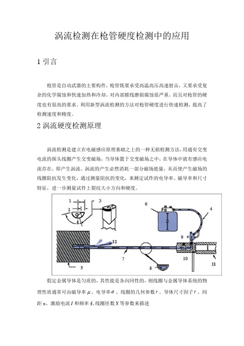
2涡流硬度检测原理涡流检测是建立在电磁感应原理基础之上的一种无损检测方法,用通有交变电流的探头线圈产生交变磁场,当导体置于交变磁场之中,在导体中就有感应电流存在,即产生涡流。
涡流的产生必然消耗一部分磁场能量,从而使产生磁场的线圈阻抗发生变化,通过测量阻抗的变化,来测定试件的电导率、磁导率和尺寸特征,进一步测量试件上裂纹大小方向和硬度。
假定金属导体是匀质的,其性能是各向同性的,则线圈与金属导体系统的物理性质通常可由磁导率μ、电导率σ、线圈的几何参数r、导体尺寸因子τ、间距x、激励电流I和频率f,线圈匝数N等参数来描述其关系函数为:),,,,,,,(N f I x r F Z τσμ= 从式中可以看出,只要知道了工件的几何尺度、材料特性参数和涡流探头的参数,这样阻抗就成为这个参数的单值函数,从而可以通过阻抗分析实现对参数的测量。
3检测系统总体方案硬度检测系统总要有硬件电路为主,软件电路相辅。
硬件部分包括动力传输系统、打标系统、计算机、涡流检测电路、传感器。
其中动力传输系统电机和传送装置。
涡流检测电路包含了单片机、激励源、功率放大、前置放大、相敏检波和滤波等。
计算机与单片机之间通过RS232,实现软件的调试。
4最小二乘法在硬度中应用在枪管质量的无损检测中,其机械性能如硬度与磁性能之间不存在确定性关系,可以通过数学方法来处理机械性能与磁性能变量之间的相关关系,对一组试验数据进行处理从而得出符合变量间关系的数学表达式,利用概率统计基础知识达到预测硬度的目的。
通过对一组试验数据分析,硬度和幅值存在线性关系,线性方程为y=ax+b 。
误差理论表明,按最小二乘法配出的直线是最好的直线。
球墨铸铁珠光体含量涡流无损智能测定

率影 响不 大 , 素 体类 似 于 纯 铁 , 饱 和 磁 化 强 度 铁 其 大约 是珠 光体 的 1 O倍 , 因此其含 量 多少强 烈影 响初 始磁 导率 , 这就 提供 了采 用 E T方 法 测定 球 墨 铸铁 C
墨铸 铁 的疲 劳 损伤度 并 预测其 寿命 。
不断增 加 。球 墨铸 铁 的性 能 与 其 球 化 率 、 光 体含 珠
量等组 织特 征有 很 大关 系 , 统 的组 织 特 征 检测 方 传
法是金 相法 , 这种 方 法 不 仅 破坏 产 品 、 时费 力 , 费 而 且 只能 进行 部 分 抽 样 , 查 结 果 具 有 随机 性 , 信 检 可
三类 。 首 先 在 分 析 了影 响 球 墨铸 铁 电磁 性 能 的主 要 因 素 的基 础 上 , 时采 用 涡 流 无 损 检 测 法 ( d yC r n T sn , C 与 同 E d ur t et g E T) e i 金 相 法 对 球 墨铸 铁 珠 光 体 含 量 进 行 了测 定 , 对检 测 数 据进 行 回 归分 析 表 明二 种 方 法 的 测 量 结 果 很 接 近 ; 后 采 用 集 成 神 经 网 然 络 处 理 涡 流 检 测 数 据 并 对 珠 光 体 含 量 进 行 了预 测 , 测 结 果 表 明基 于 集 成 神 经 网络 数 据 处 理 的 涡 流 检 测 是 一 种 快 速 智 能 识 预 别 球 墨 铸 铁 中珠 光 体 含 量 的 有 效 方 法 。
问世 以来 , 就凭 其卓 越 的性 能 成 为 最重 要 的铸 造 合 金之 一 ¨ 。 目前 随 着 制 造 业 对 产 品 零 部 件 强 度 及 轻量 化 要 求 的 不 断 增 强 , 材 料 的选 用 越 来 越 严 对 格 , 得球 墨铸 铁在 汽 车 制 造 等重 要 行 业 中 的用量 使
球墨铸铁 热处理硬度

球墨铸铁热处理硬度球墨铸铁是一种铁碳合金,其特点是铁素体基体上分布着球状石墨。
在工业生产中,球墨铸铁具有良好的应用前景,如汽车零部件、建筑材料等。
热处理是提高球墨铸铁性能的关键环节,其中硬度是衡量球墨铸铁性能的重要指标。
热处理对球墨铸铁硬度的影响主要表现在以下几个方面:1.热处理可以改变球墨铸铁的相组成。
在高温下,球墨铸铁中的铁素体逐渐转变为奥氏体,随着温度的升高,石墨球化程度提高,硬度逐渐降低。
2.热处理过程中,球墨铸铁中的碳化物析出,从而提高硬度。
在适当的温度范围内,碳化物的析出量与硬度呈正相关关系。
3.热处理还可以改善球墨铸铁的力学性能。
在高温回火过程中,铁素体转变为回火索氏体,使球墨铸铁具有较高的强度和韧性。
为实现球墨铸铁的高硬度,选择合适的热处理工艺至关重要。
常见的热处理工艺有以下几种:1.退火:将球墨铸铁加热至Ac1以上一定温度,保温一段时间后,缓慢冷却至室温。
退火可消除内应力,提高石墨球化程度,为后续热处理奠定基础。
2.调质:将球墨铸铁加热至Ac3或Ac1以上一定温度,保温一段时间后,水冷至Ms附近,再进行高温回火。
调质可提高球墨铸铁的强度和韧性。
3.感应加热:利用感应电流对球墨铸铁进行局部加热,迅速提高硬度。
感应加热适用于局部硬度要求较高的零件。
提高球墨铸铁热处理硬度的方法有以下几点:1.优化铸造工艺:提高石墨球化程度,减少碳化物析出,有利于提高热处理硬度。
2.选择合适的热处理工艺:根据零件的使用要求,选择合适的热处理工艺,以实现较高的硬度。
3.控制冷却速度:在热处理过程中,控制冷却速度有利于碳化物的析出,从而提高硬度。
总之,热处理是提高球墨铸铁硬度的重要手段。
通过合理选择热处理工艺和优化铸造工艺,可实现球墨铸铁的高硬度,满足不同应用场景的需求。
一种基于脉冲涡流无损检测技术的硬度分选仪的设计
一种基于脉冲涡流无损检测技术的硬度分选仪的设计白杨;王益祥【摘要】This paper describes a kind of hardness sorter based on nondestructive testing technology. The field programmable gate array is taken as the central control platform. and the frequeney of DDS signal generator based on FPGA is used to modulate its pulses. At the same time the signal acquisition circuit is designed.The software synchronization sampling technique is used to col ect the feedback status data and then pick up the data related to the hardness of material. At last,the correlativity between the hardness of material and characteristic data is established to distinguish the hardness status.%基于脉冲涡流无损检测技术的硬度分选仪,以FPGA作为核心控制平台,采用DDS技术发出频率可调节的脉冲波,并设计了相应的信号采集电路,通过软件同步采样技术采集反馈的状态数据,然后通过对状态数据的主成分分析,提取出和材料硬度相关的数据信息,最后通过最小二乘法建立起特征数据与材料硬度的相关关系,从而最终实现判断钢铁材料硬度状态的目的。
【期刊名称】《机械制造与自动化》【年(卷),期】2014(000)003【总页数】4页(P28-31)【关键词】脉冲涡流;无损检测;DDS;硬度分选【作者】白杨;王益祥【作者单位】南京理工大学机械工程学院,江苏南京210094;南京理工大学机械工程学院,江苏南京210094【正文语种】中文【中图分类】TH12;TM921.520 引言目前我国的钢铁产业已经形成了相当大的规模,但在实际的钢铁生产过程中,由于始终无法保证高品质的热处理工艺,使得钢铁件在经过热处理以后出现硬度过高或者硬度不足的现象常有发生,造成资源的极大浪费。
钢材硬度涡流无损检测技术的研究

钢材硬度涡流无损检测技术的研究摘要:钢材硬度是衡量其材料性能的重要指标之一,而涡流无损检测技术作为一种非接触、非破坏的检测方法,被广泛应用于钢材硬度检测中。
本文围绕钢材硬度涡流无损检测技术展开研究,介绍了该技术的原理、方法和应用,并对其优缺点进行了分析。
通过本文的研究,可以为钢材硬度涡流无损检测技术的发展提供参考和借鉴。
1. 引言钢材是一种重要的结构材料,其性能与硬度密切相关。
钢材硬度是指材料抵抗外力的能力,是衡量钢材质量和可靠性的重要指标之一。
传统的钢材硬度检测方法包括洛氏硬度测试、巴氏硬度测试等,这些方法虽然准确可靠,但需要对材料进行破坏性取样,且检测速度慢、操作复杂。
为了解决这些问题,涡流无损检测技术应运而生。
2. 钢材硬度涡流无损检测技术原理涡流无损检测技术是一种基于电磁感应原理的非接触、非破坏的检测方法。
其原理是利用涡流感应现象,通过激励线圈产生交变磁场,当磁场穿过钢材时,会在材料内部产生涡流。
根据涡流的大小和分布情况,可以间接反映出钢材的硬度。
3. 钢材硬度涡流无损检测技术方法钢材硬度涡流无损检测技术主要包括以下几个步骤:3.1 预处理:对待检测的钢材进行清洗和表面处理,以确保检测的准确性和可靠性。
3.2 激励线圈产生交变磁场:通过通电激励线圈产生交变磁场,磁场的频率和幅值需要根据钢材的特性进行选择。
3.3 检测信号采集:利用接收线圈采集材料内部产生的涡流信号,通过放大、滤波等处理,得到稳定的检测信号。
3.4 信号处理和分析:对采集到的信号进行处理和分析,提取出涡流信号的特征参数,如幅度、相位等。
3.5 硬度计算与输出:根据涡流信号的特征参数,结合预先建立的硬度模型,计算出钢材的硬度数值,并进行输出和显示。
4. 钢材硬度涡流无损检测技术的应用钢材硬度涡流无损检测技术在工业生产中具有广泛的应用价值。
它可以应用于钢材制造、加工、质量检测等环节。
例如,在钢铁企业的生产线上,可以通过涡流无损检测技术对钢材的硬度进行在线监测,及时发现生产过程中的质量问题,避免次品的产生。
球墨铸铁件无损检测综合评价方法

球墨铸铁件无损检测综合评价方法摘要:本文讲述了无损检测技术在球墨铸铁件品质检测中的原理与应用现况。
液态渗入:在铸造件表层及近表面的缺陷检测中,一般采用涡流探伤与磁粉检测结合的方式,如射线检测。
声检验主要用于检验铸造件内部结构缺陷,起声检验适合于表面光洁铸造件的球墨质量的检查,振动检测则用以表层粗粧铸造件的球墨质量的检查。
关键词:涡流探伤;射线检测;起声检验;振动检测;球墨铸铁件铸造件主要包括规格检查,外观及表层目视检查,元素检测及力学性能试验等,对要求很高或是锻造工艺易出现问题,同时还要进行无损检测技术,现阶段能够用于球墨铸铁件质量检测的无损检测技术主要包括液态渗入、磁粉探伤、涡旋、放射线、超声波和振动。
1铸造件表面和近表面缺陷检测1.1液态渗透检测液态渗透检测用于检查铸造件表面的各类开口缺陷,如外表裂痕、表层针眼等肉眼难以发现的缺陷。
渗透检测中最常见的就是着色检验,是指将渗入能力强有色板块(一般为鲜红色)液态(渗剂)浸泡或喷入铸造件表层,渗剂渗入开口缺陷内,快速去除表层渗透液层,随后向铸造件表层喷洒易干燥显示剂(又叫显像剂),当张口缺陷内剩余渗剂被吸出来时,表明剂则进行上色,使之能体现缺陷形状,规格及分布。
应当注意到渗透检测精准度也会随着待测材料外表粗糙度的增加而减少,也就是说表层越光洁度越大,在其中数控磨床抛光表层的检查精确度最佳,就算能检测出晶间裂痕也不例外。
除开着色检验以外,荧光渗透检测是很常见的一种液态渗透检测方式,需配备紫外线灯直射观察,其检测灵敏度远高于着色检测。
1.2涡流探伤涡流探伤用于深层一般不得超过6~7 mm的检查表层下缺陷处。
涡流探伤主要分放置式电磁线圈法与越过式电磁线圈法两种方式。
当样品放置通有电流的磁场电磁线圈周边后,进到试品里的交变磁场可在试品中感受垂直在鼓励磁场里的涡旋状电流量(涡旋),涡旋产生一个电磁场,磁场力激励电磁场反过来,电磁线圈中原地区电磁场部分减少,电磁线圈特性阻抗产生变化。
- 1、下载文档前请自行甄别文档内容的完整性,平台不提供额外的编辑、内容补充、找答案等附加服务。
- 2、"仅部分预览"的文档,不可在线预览部分如存在完整性等问题,可反馈申请退款(可完整预览的文档不适用该条件!)。
- 3、如文档侵犯您的权益,请联系客服反馈,我们会尽快为您处理(人工客服工作时间:9:00-18:30)。
( S e c ( J n d F o u n d  ̄, Oo n g f e , l T r u c k s C o . , I t d . , S h i y a n 4 4 2 0 1 3 , C h i n a )
Ab s t r a c t : T h e n r i n ( i p 1 e a n d c h a r a c t e r i s t i c s o f e d d y e u n ' e l f t me t h o d f o r me a s u r i n g h a r d n e s s w e r e i n t r o d m e d . T h e s e l e c t i o n t l f
r e l e v a n t D a r _ a n 1 e t e r s s u c h a s c U I T e n t re f q u e n c y , s h a p e a n d s t r u c t u r e o f c o i l a n d d e t e c t i o n me t h o d we r e e l a b o r a t e d . T i l e r e l e v a n t t e s t i s 0 f MA I l i f e r e n t i a 1 s h e l l w e r e a n a l y z e d a n d v e r i i f e d . T h e f o l l o wi n g r e s u l t s w e r e e o n e l u d e d: I l l t h e e d d y C U l T e n t t e s t i n g , t l 1 e c h a n g e i n t h e h a r d n e s s o f p a r t s wi l l C a u s e c h a n g e s i n t h e i mp e d a n c e , r e s u l t i n g t h e i mp e d a n ( e ma p p o s i t i o n( ’ h a n g e s ・
参数 的选择 , 并通 过对轿 车零件 M A差速器壳体进行相关的试验 和验 汪。得 } H 以下结论 : 在 涡流检测 时 , 零件硬度的变
化会引起零件阻抗的变化 , 导 致零件 往阻抗平面罔位置产生变化 。 虽然涡流检测不能进行 定量检测得到 具体硬度值 , 但 口 1以通过检 测零 件在阻抗平面罔 中的位置来分选 出零 件是否异常 , 对零件硬度进行 定性分选 , 并快速有效判 定零件是 否异常 。因此 , 涡流检测分选球 墨铸铁零件的硬度是一种高速有效的无损检测方 法。 关键词 : 球墨铸铁 ; 涡流检 测 ; 硬度 中图分类号 : T G 2 5 5
,
文献标识码 : B
文章编号 : 1 0 0 3 — 8 3 4 5 ( 2 0 1 6 ) 0 6 — 0 0 3 4 — 0 4
DOI : l 0 . 3 9 6 9 / / . i s s n . 1 0 0 3 — 8 3 4 5 . 2 0 1 i o n o f E d d y Cu r r e n t Te c h n o l o g y i n Ha r d n e s s T e s t i n g o f No d u l ar I r o n
No d u l a r I r o l l
涡流 技 术 在 球 墨铸 铁 硬 度检 测 中 的应 用
张 文 杰
( 东风商用车有限公 司 铸造 二 厂 , 湖北 _ } 1 堰 4 4 2 0 1 3 )
摘要 : 介 了涡流法检测硬度的 理 搜特点 , 阐述了在检测过程 中检测 电流频 率 、 线圈形状和结构 以及柃测方式等相关
Al t h o u g h e d d y c u “e n t t e s t i n g c a n t b e u s e d i n q u a n t i t a t i v e d e t e  ̄ ‘ t i o n a n d g a v e h a r d n e s s v a l u e s , i t s t i l l c o u h l q u a l i t a t i v e s c l a i n g
t h e h a r d n e s s o f t h e p a r t s b y i mp e d a n c e d i a g r a m o f t h e l o c a t i o n t o s o r t o u t t h e a b n o r ma l p a l l s a n t i q u i c k l y d e l e r mi n e t h e a h n o r ma l o n e .T h e r e f o r e , t h e e d d y c u r r e n t i n s p e e t i o n a n d s o r t i n g n o d u l a r e a s t i r o n p a ns h a , d n e s s wa s a q u i c k a l l ( t e f f e ( ‘ n o n — — d e s t r u c t i v e t e s t i n g me t h o d .