MAX6318MHUK28BZ中文资料
MAX882中文资料
19-0275; Rev 0; 12/94
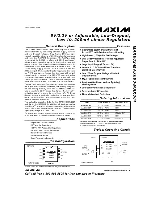
5V/3.3V or Adjustable, Low-Dropout, Low IQ, 200mA Linear Regulators
_______________General Description
The MAX882/MAX883/MAX884 linear regulators maximize battery life by combining ultra-low supply currents and low dropout voltages. They feature 200mA output current capability at up to +125°C junction temperature and come in a 1.5W SOIC package. The 1.5W package (compared to 0.47W for standard SOIC packages) allows a wider operating range for the input voltage and output current. The MAX882/MAX883/MAX884 use a Pchannel MOSFET pass transistor to maintain a low 11µA (15µA max) supply current from no-load to the full 200mA output. Unlike earlier bipolar regulators, there are no PNP base current losses that increase with output current. And, in dropout, the MOSFET does not suffer from excessive base currents that occur when PNP transistors go into saturation. Typical dropout voltages are 220mV at 5V and 200mA, or 320mV at 3.3V and 200mA. The MAX882 features a 7µA standby mode that disables the output but keeps the reference, low-battery comparator, and biasing circuitry alive. The MAX883/MAX884 feature a shutdown (OFF) mode that turns off all circuitry, reducing supply current to less than 1µA. All three devices include a low-battery-detection comparator, foldback current limiting, reverse-current protection, and thermal overload protection. The output is preset at 3.3V for the MAX882/MAX884 and 5V for the MAX883. In addition, all devices employ Dual Mode™ operation, allowing user-adjustable outputs from 1.25V to 11V using external resistors. The input voltage supply range is 2.7V to 11.5V. For low-dropout linear regulators with output currents up to 500mA, refer to the MAX603/MAX604 data sheet.
MAX830中文资料

STEP-DOWN CONVERTER
* CoilCraft DO3316-104
________________________________________________________________ Maxim Integrated Products
1
Call toll free 1-800-998-8800 for free samples or literature.
* THIS THERMAL RESISTANCE NUMBER IS WITH THE DEVICE WELL MOUNTED ON 1 oz. COPPER WITH THERMAL PASTE BETWEEN THE IC AND THE UNDERLYING GROUND PLANE. LOWER THERMAL RESISTANCE IS POSSIBLE (SEE APPLICATIONS SECTION).
NUAL KIT MA ATION U EET L H A S V A E T WS DA FOLLO
___________________________Features
o Input Range: Up to 30V o 1A On-Chip Power Switch o Adjustable Output (MAX830) Fixed Outputs: 5V (MAX831) 3.3V (MAX832) 3V (MAX833) o 100kHz Switching Frequency o Excellent Dynamic Characteristics o Few External Components o 8mA Quiescent Current o 16-Pin SO Package o Evaluation Kit Available
日业BM560X CM560系列起重专用变频器用户手册V2.0
7.1 F0 组基本功能组.................................................................................................................................................. 67 7.2 F1 组启停控制...................................................................................................................................................... 72 7.3 F2 组 V/F 控制参数..............................................................................................................................................75 7.4 F3 组矢量控制参数.............................................................................................................................................. 77 7.5 F4 组电机参数...................................................................................................................................................... 79 7.6 F5 组输入端子...................................................................................................................................................... 80 7.7 F6 组输出端子...................................................................................................................................................... 85 7.8 F7 组 辅助功能及人机界面功能....................................................................................................................... 86 7.9 F8 组通信功能...................................................................................................................................................... 93 7.10 F9 组故障与保护................................................................................................................................................ 94 7.11 FA 组过程控制 PID 功能...................................................................................................................................96 7.12 FB 组摆频功能....................................................................................................................................................98 7.13 FC 组多段速功能及简易 PLC 功能................................................................................................................. 99 7.14 FD 组(保留)................................................................................................................................................. 103 7.15 FE 组 增强组....................................................................................................................................................104 7.15 FF 组 厂家参数组............................................................................................................................................104
科尔摩根AKM 同步伺服电机 选型指南说明书
K O L L M O R G E N | A K o l l m o r g e n C O M PA N Y欢迎来到科尔摩根官方微信科尔摩根3目录u AKM ™ 同步伺服电机4u AKD ™ 伺服驱动器8u AKM ™ 各种选件12u AKM ™ 防水型和食品级防水型电机13u AKM ™ 系统综述14u AKM ™ 图纸和性能数据AKM1x 16AKM2x 20AKM3x24AKM4x 28AKM5x 34AKM6x 40AKM7x 44AKM8x48u L 10 轴承疲劳寿命和轴负载53u 反馈选件56u 抱闸选件60u 伺服电机连接器选件61u 型号命名67u MOTIONEERING ® Online71科尔摩根A K M 同步伺服电机选型指南克服设计、采购和时间障碍科尔摩根明白:帮助原始设备制造商的工程师克服障碍,可以显著提高其工作成效。
因而,我们主要通过如下三种方式来提供帮助:集成标准和定制产品在很多情况下,理想方案都不是一成不变的。
我们拥有专业应用知识,可以根据全面的产品组合来修改标准产品或开发全定制解决方案,从而为设计奠定良好的基础。
提供运动控制解决方案而不仅仅是部件在各公司减少供应商数量和工程人力的过程中,他们需要一家能够提供多种集成解决方案的全系统供应商。
科尔摩根就采用了全面响应模式,为客户提供全套解决方案,这些方案将编程软件、工程服务以及同类优秀的运动控制部件结合起来。
覆盖全球我们在美洲、欧洲、中东和亚洲拥有众多直销、工程支持单位、生产工厂以及分销商,临近全球各地的原始设备制造商。
这种便利优势可以加速我们的供货过程,根据客户需要随时随地供货。
财务和运营稳定性科尔摩根隶属于Fortive 公司。
Fortive 业务系统是推动Fortive 各部门发展的一个关键力量。
该系统采用“不断改善”(Kaizen )原理。
由高素质人才构成的多学科团队使用世界级的工具对过程进行评估,并制定相关计划以达到卓越的性能。
SACE Tmax XT 型号的模具式电路保护器产品说明书
—MOLDED C A SE CIRCUIT-BRE AKERS SACE Tmax XTBreak new groundS ACE TM A X X T M O L D ED C A SE CI R C U IT-B R E A K ER S (M CCB S)—A molded case circuit-breaker range that ensures extreme performance and protection features up to 1600A. Designed to maximize ease of use, integration and connectivity. Built to deliver safety, reliability and quality.—Table of contents004 – 005SACE Tmax XT006 – 007Added values008 – 009Key features012 – 013Choosing the right product 014 – 015 Accessories018 – 021Products in detail024 – 025E lectronic trip units—SACE Tmax XTThe right choice: a complete circuit-breaker range for any solutionSACE Tmax XT2SACE Tmax XT5SACE Tmax XT7SACE Tmax XT44S ACE TM A X X T M O L D ED C A SE CI R C U IT-B R E A K ER S (M CCB S)5SACE Tmax XT3SACE Tmax XT1 SACE Tmax XT66S ACE TM A X X T M O L D ED C A SE CI R C U IT-B R E A K ER S (M CCBS)There is a lot more to the range of SACE Tmax XT than what meets the eye, and the benefits for your business are notice-able. To start with, the whole selection and ordering process has been overhauled to make it far easier to get your hands on the parts you need, speeding things up by about 30%. Installation has been simplified to increase user-friendliness, frames have been streamlined to save space, and improved connectivity - such as Bluetooth and Ekip mobile - will save you considerable time. Another additional benefit is the reliable cloud connectivity and overall increase in information available, meaning diagnostics and maintenance are vastly improved, resulting in less downtime. Finally, thanks to the smart power controller concept, overall energy consumption can be reduced by up to 20%.—Added value each step of the way There is more than just a circuit-breaker in the SACE Tmax XT rangeA new generation of molded case circuit-breakers delivering great added value.7Continuous operationOptimuminterfaceSafety and protectionSpeed up your projects OptimizedlogisticsSpace savingSpeed up your projects Easy toinstallContinuous operation EnergyefficiencyCommissioningThe SACE Tmax XT range offers the potential to save serious time. Thanks to simplified installation of frames, integrating the circuit-breakers into a communication network, trip unit settings per-formed via LCD and Bluetooth and Ekip Mobile con-nectivity , you stand to save up to 40% time overall.Diagnostics and maintenanceWith up to 30% more data available on the cloud and ABB unique power controller concept, it is far easier to diagnose problems and carry out necessary maintenance. This helps to prevent faults, restore energy more quickly and avoid any unnecessary charging of utilities.Energy savingThe SACE Tmax XT range comes with the exclu-sive ABB-patented Ekip Power Controller which monitors installation loads and can limit the amount of power consumed at any time. The result is an overall reduction in power consump-tion of up to 20% and lower energy bills. Further-more, you have 1% energy measurement accuracy according to IEC 61557-12.Selection, ordering and handling 30% faster thanks to part numbersreduction (-10%), online configurator (-40% time) and smart packaging (-30% space).A D D ED VA LU ES8S ACE TM A X X T M O L D ED C A SE CI R C U IT-B R E A K ER S (M CCB S)—01 Choose and custom-ize exactly the rightproducts for your needs, based on how you will use them. 10,000 solutions in one click —02 Effective energy management: 20% less power consump-tion with Power Controller enabled —03 Top reliability:Products designed and tested to exceed stan-dard requirements. More than 30 certificationsCloud-connectedTailor-madetechnologyCloud-connectedBeing connected is a key feature of today’s tech-nology and the SACE Tmax XT range of circuit- breakers offers more than just standalone pro-tection. Being considered key elements of an electrical distribution system, Tmax XT circuit- breakers give you the ability to monitor andmanage a wealth of information, easily, wherever you are. So even when on the road, anytime of the day or night, the power of full-access flexi-bility is in your hands.—Being able to monitor everything while being off-site provides a genuine feeling of you being in control at all times.Tailor-made solutionsJust because your project is complex, this does not mean your circuit-breaker setup has to be. All frames from XT1 to XT7 provide a common pro d uct experience that is backed up by a com-prehensive range of accessories with intuitive interfaces and ergonomic design. With maximum Outstanding technologyFlexibility is nothing without performance and the SACE Tmax XT range is able to deal with the most extreme breaking capacities, regardless of operating voltage, application, and environmen-tal conditions. Combined with the most precise electronic trip units in the smallest of frames, this ensures continuity of service and equipment pro-tection at all times.Top-level qualityAlmost a century of research and experience results in highly-reliable, top-level products that are ready to face all future challenges. Products like the SACE Tmax XT range set standards for edge technologies. Safety, product quality and reliability under pressure are fundamental to all ABB prod-ucts and the SACE Tmax XT range is no different.—Break new ground Key features of an outstanding product9—01—03—02—E A S E OF US E A N D I NS TA LL ATI O NMaximum flexibility for every application – SACE Tmax XT sets the new standard for electrical installations.Easy selection, one-size-fits-all accessories and intuitive design pave the way for smart manufacturing of panels and fast upgrades. Even for the most critical projects.12S ACE TM A X X T M O L D ED C A SE CI R C U IT-B R E A K ER S (M CCBS)Heavy duty Basic functionalityThermal-magnetic, Ekip DipEkip Touch/Hi-Touch —• Standard performance• Icu 70kA at 415/480V AC —• Extreme breaking capacity • 200kA at 415V AC• 100kA at 690V AC—Thermal-magnetic• TMF - TMD - TMA - TMG - MF - MAElectronic• Ekip Dip LIG - LS/I - LSI - LSIG -G Dip LS/I - M Dip I - M Dip LIU -M Dip LRIUNo communication/No display —Ekip Touch • LSI - LSIG - G Touch LSIG - M Touch LRIU - + Energy M Ekip Hi-Touch • LSI - LSIG - G Hi-Touch LSIG Full connectivity - Advanced logic - Power managementUniversally compatibleThe world of circuit-breakers is a complex one,yet choosing the right device for your individualneeds has never been simpler thanks to SACETmax XT range. Maybe you are looking for a basicprotection device for a standard distributionplant. Or perhaps you need something morecomplex, such as a device that integrates —Choosing the right circuit-breaker has never been so easyYou consider what you need. We’ll show you what is possible.protection, automation, measuring and commu-nication into a cloud-based supervision system. Whatever you are looking for, with a wealth of customization possibilities and a range of possible solutions depending on the breaking part and trip unit you choose, the power of circuit breakingis firmly in your hands.Possible combinations within the rangeBasic functionalityWhether you are a hotel owner or planning a production line,where you need to consider the overall power voltage over aperiod of time, the whole SACE Tmax XT range offers all thecircuit breaking power you need to keep your business run-ning long into the future.Thermal-magnetic, Ekip Dip – manual operationThis either consists of the standard thermal-magnetic tripunit intended for basic protection or the Ekip Dip trip unit,the first level of electronic trip unit that can provide in-creased accuracy, a wider regulation range, delayedshort-circuit protection and individual trip information.Heavy duty When it comes to heavy duty usage – whether it’s ships, chemical parks, mining, or heavy duty machinery – the SACE Tmax XT2, XT4, XT5 and XT7 frames are designed to work well beyond the normal constraints when you will be pushing the limits of your installation to the maximum.Ekip Touch/Hi-Touch – cloud functionality Once you are working with the XT2, XT4 XT5 or XT7 frames, all activity can be remotely monitored via the cloud thanks to the Ekip Touch/Hi-Touch trip units which send all data to the ABB Ability TM EDCS and can be monitored through smart-phone or tablet whenever and wherever you like.CH O OSI N G TH E R I G HT PR O D U C T13Tmax XT1Tmax XT2Tmax XT3Tmax XT4Tmax XT5Tmax XT6Tmax XT7Basic functionality (Icu@415V<70 kA)Heavy duty (Icu@415V>70 kA)Thermal-magnetic trip units Ekip Dip (standard electronic)Ekip Touch/Hi-Touch (smart electronic)14S ACE TM A X X T M O L D ED C A SE CI R C U IT-B R E A K ER S (M CCB S)—Udipsusam esciis pariamet, que et faci quia conet, sit magnatia dolora esciis pariamet, que et faci solupiste dollorpostem pliqui cum image—AccessoriesExpand the capabilities of the SACE Tmax XT rangeIntegrating circuit-breakers into any installation requires different levels of optimization. Whether physical, electrical, operational or safety-focused, accessories take SACE Tmax XT to the next level.AccessoriesA large range of connections has been conceived to match the most common distribution systems. Auxiliary contacts can provide precise information regarding breaker status and plant conditions, maximizing operator awareness and the overall accuracy of a supervision system. In addition, dif-ferent types of coils and motor operator versions, designed to operate with the most common voltage sources and reduced power consumption, enable the possibility to control all installations remotely. Residual current devices up to 630A, sig-naling modules, installation components (e.g. phase barriers, terminal covers), key-locks and padlocks are just a few examples of the care taken to safeguard appliances and operators alike. Metering15Various accessories are also available:1. Breaking unit2. Trip units3. Front4. Polish plate5. Terminal covers6. Auxiliary contacts7. Key lock8. Service releases9. Communication module10. C onversion kit for plug-in/withdrawable versions11. G uide of fixed part in thewithdrawable version 12. Fixed part - FP 13. Front for lever operating mechanism - FLD 14. Stored energy motor operator - MOE 15. Direct rotary handle - RHD 16. Transmitted rotary handle - RHE 17. Conversion kit RHE > RHS 18. Cable rack 19. Phase separators 20. R ear orientated terminals - R 21. F ront extended spread terminals - ES 22. Front terminals for copper-aluminium - FC CuAl 23. Front extended terminals - EF 24. Residual current release2419162122231761012911723138520151418415ACCE SSO R IE SS ACE TM A X X T M O L D ED C A SE CI R C U IT-B R E A K ER S (M CCB S)—PER FO R M A NCE A N D PROTEC TI O NContinuity of service and equipmentprotection – SACE Tmax XT sets the new standard when extreme breaking capacity is needed. Sharing the same logic, interfaces andfeatures regardless of operating voltageand environmental conditions. Embeddingthe most advanced protection into thesmallest of frames.S ACE TM A X X T M O L D ED C A SE CI R C U IT-B R E A K ER S (M CCB S)SACE Tmax XT1The founderSmall, reliable, versatile. Your reliable partner for all standard applications.At a glance:• Up to 160A• For basic functionalities• Dimensions 76.2x70x130 (WxDxH mm)• Thermal-magnetic trip unit SACE Tmax XT2The aspirerCompact yet powerful. It fits everywhere and is able to deal with all complex tasks. At a glance:• Up to 160A• For heavy duty• Dimensions 90x82.5x130 (WxDxH mm)• Thermal-magnetic, Ekip Dip,Ekip Touch/Hi-Touch18—The SACE Tmax XT range at a glance The world of circuit breaking and circuit protection in your handsThe SACE Tmax XT range takes circuit protection to the nextlevel. Designed to perform at extremely high levels, simpleto install and able to provide increasingly better safety,there is a frame to meet each and every one of your require-ments. From a basic solution for standard applications -such as hotels - through to advanced, heavy-duty applica-tions with cloud connectivity for ships, chemical parks orairports, the new range has got it covered: securely, profes-sionally, reliably.19PR O D U C TS I N D E TA I LSACE Tmax XT4The entrepreneur A forward-thinking, multitasker. It finds solutions for all levels of complexity.At a glance:• Up to 250A • For heavy duty • Dimensions 105x82.5x160 (WxDxH mm)• Thermal-magnetic, Ekip Dip,Ekip Touch/Hi-TouchSACE Tmax XT3The workhorseSmall and experienced. For standardapplications that need few efforts.At a glance:• Up to 250 A• For basic functionalities• Dimensions 105x70x150 (WxDxH mm)•Thermal-magnetic trip unitS ACE TM A X X T M O L D ED C A SE CI R C U IT-B R E A K ER S (M CCBS)SACE Tmax XT5The gamechanger.Compact, extremely powerful and flexible. It shows the world what a circuit-breaker of the future can do, today. At a glance:• Up to 630A• For heavy duty• Dimensions 140x103x205 (WxDxH mm)• Thermal-magnetic, Ekip Dip, Ekip Touch/Hi-Touch SACE Tmax XT6The carpenterBuilt to last. It completes all assignments it has been entrusted with.At a glance:• Up to 1000A• For basic functionalities• Dimensions 210x103.5x268 (WxDxH mm)• Thermal-magnetic, Ekip Dip2021PR O D U C TS I N D E TA I LSACE Tmax XT7 M The motorized superhero The ultimate choice, with motor. It deals with the most heavy-duty demands smoothly.At a glance:• Up to 1600A • For heavy duty • Dimensions 210x178x268 (WxDxH mm)• Ekip Dip, Ekip Touch/Hi-TouchSACE Tmax XT7The superheroThe ultimate choice. It deals with the mostheavy-duty demands effortlessly.At a glance:• Up to 1600A• For heavy duty• Dimensions 210x166x268 (WxDxH mm)•Ekip Dip, Ekip Touch/Hi-TouchS ACE TM A X X T M O L D ED C A SE CI R C U IT-B R E A K ER S (M CCB S)—DATA A N D CO N N EC TI V IT YPlant management of the future – SACE Tmax XT sets the new standard in modern plant and energy management. Access, monitor and control information remotely, anywhere, at any time. Improving efficiency and saving energy.24S ACE TM A X X T M O L D ED C A SE CI R C U IT-B R E A K ER S (M CCB S)—01 All the tools neededto set up a compe-tent and effectiveenergy managementstrategy. 30% moreinformation abouta running system toempower ABB Ability TM P r o t e c t i o n a n di n f o r m a t i o n AccuracyThermal-magnetic trip units Thermal-magnetic trip units are intended for the protection of AC and DC networks. They are a solution for basic protection such as overloads and short-circuits.Ekip Dip trip unitsEkip Dip trip units represent the first level ofelectronic trip unit and are used to protect ACnetworks. Compared to thermal-magnetic tripunits, they can provide increased accuracy, a widerreg ulation range, delayed short-circuit protection,in di v idual trip information and test capa bility.Ekip Touch/Hi-Touch trip units Ekip Touch/Hi-Touch trip units offer state-of-the-art technology for AC-network protection. These trip units integrate a great number of protection and automation functionalities, performed with best-in-class accuracy. Measurement and supervi-sion data can be transmitted both on the local communication network (the most popular com-munication protocols are available) or directly over the Internet. Configuration of the trip unit is extremely user-friendly, mainly on the sizes where a color touchscreen display is available. Furthermore, as operational requirements evolve,for the first time ever customers can downloadnew functions from the ABB Ability Marketplace TM ,choosing among more than fifty different protec-tion, metering and automation functionalities.—Electronic trip units Ekip Dip and Ekip Touch/Hi-Touch The network under controlWhen it comes to accurate protection of the network, you cannot go wrong with Ekip Dip and Touch technology.Trip unit rangeThe protection units available for the SACE Tmax XTrange is organized in three layers, characterizedby increasing performance, interfaces, informa-tion sets and integration functions. Each layerincludes several trip unit versions, designed to match specific application needs such as distribu-tion, generator protection and motor protection.25CampaignS ACE TM A X X T M O L D ED C A SE CI R C U IT-B R E A K ER S (M CCB S)—QUA LIT Y A N D R ELI A B I LIT YAbsolute attention to detail, withstyle – from design to manufacturing, SACETmax XT sets the new standard for edgetechnologies. Almost a century of research and experience means top-level products that areready to face future challenges.© Copyright 2019 ABB. All rights reserved.Specifications subject to change without notice.9A K K 107046A 3308 - 05/2019—ABB SACEElectrification business Smart Power business line 5, Via PescariaI-24123 Bergamo - ItalyPhone: +39 035 395-111go.abb/xt。
18HM单相蜂巢电机保护器说明说明书
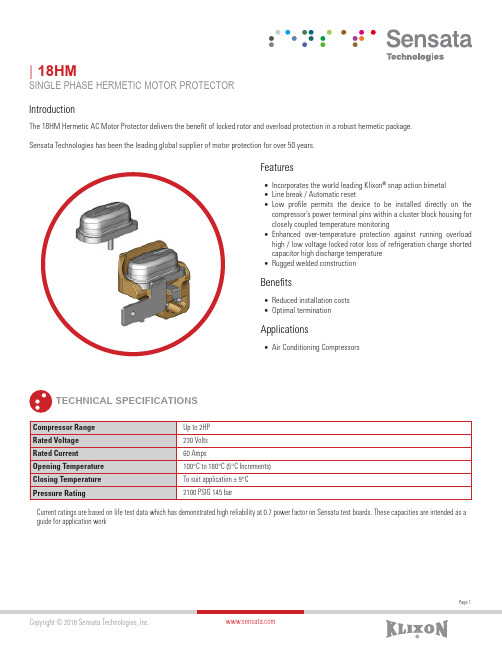
Page 1| 18HMSINGLE PHASE HERMETIC MOTOR PROTECTORIntroductionThe 18HM Hermetic AC Motor Protector delivers the benefit of locked rotor and overload protection in a robust hermetic package.Sensata Technologies has been the leading global supplier of motor protection for over 50 years.FeaturesBenefitsApplications• Incorporates the world leading Klixon ® snap action bimetal • Line break / Automatic reset• Low profile permits the device to be installed directly on the compressor’s power terminal pins within a cluster block housing for closely coupled temperature monitoring• Enhanced over-temperature protection against running overload high / low voltage locked rotor loss of refrigeration charge shorted capacitor high discharge temperature • Rugged welded construction• Reduced installation costs • Optimal termination• Air Conditioning CompressorsTECHNICAL SPECIFICATIONSCurrent ratings are based on life test data which has demonstrated high reliability at 0.7 power factor on Sensata test boards. These capacities are intended as a guide for application workPage 2All dimensions in millimeters (inches).DIMENSIONS AND SCHEMATICSElectrical SchematicORDERING OPTIONSExample : 18HM-XXX-XXXQuick Connects, Wire Leads, Sleeves, etc.When making an inquiry for Klixon ® hermetically sealed motor protectors, be certain to specify the entire part number for your application, if known. The six digits following the series identification indicate your specific electrical and physical requirement.Americas+1 (888) 438 2214*******************Europe, Middle East & Africa +31 (74) 357 8156*******************************Asia Pacific***************************.com China +86(21)2306 1651Japan +81(45)277 7104Korea +82 (53) 644 9685India / Middle East +91(40)4033 9611Rest of Asia +65 (6478) 6860Page 3Rev:07/31/18CONTACT USSensata Technologies, Inc. (“Sensata”) data sheets are solely intended to assist designers (“Buyers”) who are developing systems that incorporate Sensata products (also referred to herein as “components”). Buyer understands and agrees that Buyer remains responsible for using its independent analysis, evaluation and judgment in designing Buyer’s systems and products. Sensata data sheets have been created using standard laboratory conditions and engineering practices. Sensata has not conducted any testing other than that specifically described in the published documentation for a particular data sheet. Sensata may make corrections, enhancements, improvements and other changes to its data sheets or components without notice.Buyers are authorized to use Sensata data sheets with the Sensata component(s) identified in each particular data sheet. HOWEVER, NO OTHER LICENSE, EXPRESS OR IMPLIED, BY ESTOPPEL OR OTHERWISE TO ANY OTHER SENSATA INTELLECTUAL PROPERTY RIGHT, AND NO LICENSE TO ANY THIRD PARTY TECHNOLOGY OR INTELLECTUAL PROPERTY RIGHT, IS GRANTED HEREIN. SENSATA DATA SHEETS ARE PROVIDED “AS IS”. SENSATA MAKES NO WARRANTIES OR REPRESENTATIONS WITH REGARD TO THE DATA SHEETS OR USE OF THE DATA SHEETS, EXPRESS, IMPLIED OR STATUTORY, INCLUDING ACCURACY OR COMPLETENESS. SENSATA DISCLAIMS ANY WARRANTY OF TITLE AND ANY IMPLIED WARRANTIES OF MERCHANTABILITY, FITNESS FOR A PARTICULAR PURPOSE, QUIET ENJOYMENT, QUIET POSSESSION, AND NON-INFRINGEMENT OF ANY THIRD PARTY INTELLECTUAL PROPERTY RIGHTS WITH REGARD TO SENSATA DATA SHEETS OR USE THEREOF.All products are sold subject to Sensata’s terms and conditions of sale supplied at SENSATA ASSUMES NO LIABILITY FOR APPLICATIONS ASSISTANCE OR THE DESIGN OF BUYERS’ PRODUCTS. BUYER ACKNOWLEDGES AND AGREES THAT IT IS SOLELY RESPONSIBLE FOR COMPLIANCE WITH ALL LEGAL, REGULATORY AND SAFETY-RELATED REQUIREMENTS CONCERNING ITS PRODUCTS, AND ANY USE OF SENSATA COMPONENTS IN ITS APPLICATIONS, NOTWITHSTANDING ANY APPLICATIONS-RELATED INFORMATION OR SUPPORT THAT MAY BE PROVIDED BY SENSATA.Mailing Address: Sensata Technologies, Inc., 529 Pleasant Street, Attleboro, MA 02703, USA.(European Directive 2002/95/EC Restrictions On Use Of Hazardous Substances)AGENCY APPROVALS & CERTIFICATIONSWARNINGSRISK OF MATERIAL DAMAGE AND HOT ENCLOSURE• The product’s side panels may be hot, allow the product to cool before touching • Follow proper mounting instructions including torque values • Do not allow liquids or foreign objects to enter this productFailure to follow these instructions can result in serious injury, or equipment damage.HAZARD OF ELECTRIC SHOCK, EXPLOSION OR ARC FLASH• Disconnect all power before installing or working with this equipment • Verify all connections and replace all covers before turning on powerFailure to follow these instructions will result in death or serious injury。
Turck磁感应传感器产品说明书

T 08:30:42+02:00型号BIM-UNT-AY1X/S1139货号4685763通过速度ð 10 m/s 重复性ï ± 0.1 mm 温度漂移ð 0.1 mm 磁滞ð 1 mm环境温度-25…+70 °C 输出性能2线, NAMUR 开关频率 1 kHz电压Nom. 8.2 VDC 无激励电流损耗ð 1.2 mA 激励电流损耗ï 2.1 mA认证依据KEMA 04 ATEX 1152 X 内置 电感(L ) / 电容 (C )180 nF / 350 µH防爆标志防爆标识为II 1 G/Ex ia IIC T6/II 1 D Ex ia D 20 T95°C(最大 U = 20 V, I = 60 mA, P = 80 mW)设计方型, UNT 尺寸28 x 5 x 6 mm 外壳材料塑料, PP 感应面材料塑料, PP 紧固螺母的固定扭矩0.4 Nm 连接电缆线缆材质3 mm, 蓝, Lif9YYW, PVC, 2 m线缆横截面2 x 0.14mm 防震动性55 Hz (1 mm)防冲击性30 g (11 ms)防护等级IP67MTTF2283 years 符合SN 29500 (Ed.99) 40 °C认证安装在以下剖面.Cylindrical design E N K F 开关状态指示LED指示灯 黄可供货电缆夹sATEX 防爆认证 II组设备,设备等级1G,可用为气体危险0区sATEX 防爆认证II组设备,设备等级1D,适用于粉尘危险2区s 适于T型槽气缸,无需安装附件s 可选择附件安装于其他外型气缸上s 单手可安装s 微调装置和固定器可直接安装在传感器上s 稳固的安装s 磁阻式传感器s 2线直流, nom. 8.2 VDCs输出遵循本安型DIN EN 60947-5-6(NAMUR)标准s输出方波信号s 常开s电缆连接接线图功能原理磁感应传感器感应磁场。
SIM SAM 6 8Pin 机械插槽卡插座说明书

CCM03-3003LFT R102 Sim card connector 8 inlay contacts with hinged cover
CCM03-3004LFT R102 Sim card connector 8 inlay conatcts with hinged cover with plastic peg
Fixed cover: 3N max
Card extraction force
Hinged cover: 1N max Fixed cover: 0,80N min / 3N max
Contact force
0,25N min / 0,50N max
Slide locking force
Soldering Process
Compatible with lead free SMT soldering process
SIM/SAM
How To Order Part number list is shown below. For individual part details, please refer to the following pages.
5,08 3,7 9,65
10,16 20,32
6x
1,3
0,7 25˚
S 3,5
Slider locked
29,65 13,8
2,45 R 1,9
1,25 0,7
ø1±0,05 DETAIL A Scale 5
1,25
11,25 17,2
Normally open 100 mΩ max 250 Vrms min 1 mA min / 10m A max 0.2 VA
Environment Data
- 1、下载文档前请自行甄别文档内容的完整性,平台不提供额外的编辑、内容补充、找答案等附加服务。
- 2、"仅部分预览"的文档,不可在线预览部分如存在完整性等问题,可反馈申请退款(可完整预览的文档不适用该条件!)。
- 3、如文档侵犯您的权益,请联系客服反馈,我们会尽快为您处理(人工客服工作时间:9:00-18:30)。
___________________________________________________________________Selector Guide________________General DescriptionThe MAX6316–MAX6322 family of microprocessor (µP)supervisory circuits monitors power supplies and microprocessor activity in digital systems. It offers sev-eral combinations of push/pull, open-drain, and bidirec-tional (such as Motorola 68HC11) reset outputs, along with watchdog and manual reset features. The Selector Guide below lists the specific functions available from each device. These devices are specifically designed to ignore fast negative transients on V CC . Resets are guaranteed valid for V CC down to 1V.These devices are available in 26 factory-trimmed reset threshold voltages (from 2.5V to 5V, in 100mV incre-ments), featuring four minimum power-on reset timeout periods (from 1ms to 1.12s), and four watchdog timeout periods (from 6.3ms to 25.6s). Thirteen standard ver-sions are available with an order increment requirement of 2500 pieces (see Standard Versions table); contact the factory for availability of other versions, which have an order increment requirement of 10,000 pieces.The MAX6316–MAX6322 are offered in a miniature 5-pin SOT23 package.________________________ApplicationsPortable Computers Computers ControllersIntelligent InstrumentsPortable/Battery-Powered Equipment Embedded Control Systems____________________________Features♦Small 5-Pin SOT23 Package♦Available in 26 Reset Threshold Voltages2.5V to 5V, in 100mV Increments ♦Four Reset Timeout Periods1ms, 20ms, 140ms, or 1.12s (min)♦Four Watchdog Timeout Periods6.3ms, 102ms, 1.6s, or 25.6s (typ) ♦Four Reset Output StagesActive-High, Push/Pull Active-Low, Push/Pull Active-Low, Open-Drain Active-Low, Bidirectional♦Guaranteed Reset Valid to V CC = 1V♦Immune to Short Negative V CC Transients ♦Low Cost♦No External ComponentsMAX6316–MAX63225-Pin µP Supervisory Circuits withWatchdog and Manual Reset________________________________________________________________Maxim Integrated Products 119-0496; Rev 7; 11/07_______________Ordering InformationOrdering Information continued at end of data sheet.*The MAX6318/MAX6319/MAX6321/MAX6322 feature two types of reset output on each device.Typical Operating Circuit and Pin Configurations appear at end of data sheet.For pricing, delivery, and ordering information, please contact Maxim Direct at 1-888-629-4642,or visit Maxim’s website at .Specify lead-free by replacing “-T” with “+T” when ordering.ELECTRICAL CHARACTERISTICS(V CC = 2.5V to 5.5V, T A = -40°C to +125°C, unless otherwise noted. Typical values are at T A = +25°C.) (Note 1)M A X 6316–M A X 63225-Pin µP Supervisory Circuits with Watchdog and Manual Reset 2_______________________________________________________________________________________ABSOLUTE MAXIMUM RATINGSStresses beyond those listed under “Absolute Maximum Ratings” may cause permanent damage to the device. These are stress ratings only, and functional operation of the device at these or any other conditions beyond those indicated in the operational sections of the specifications is not implied. Exposure to absolute maximum rating conditions for extended periods may affect device reliability.Voltage (with respect to GND)V CC ......................................................................-0.3V to +6V RESET (MAX6320/MAX6321/MAX6322 only)...... -0.3V to +6V All Other Pins.........................................-0.3V to (V CC + 0.3V)Input/Output Current, All Pins.............................................20mAContinuous Power Dissipation (T A = +70°C)SOT23-5 (derate 7.1mW/°C above +70°C)...............571mW Operating Temperature Range..........................-40°C to +125°C Junction Temperature......................................................+150°C Storage Temperature Range..............................-65°C to +160°C Lead Temperature (soldering, 10s).................................+300°CTH available in 100mV increments from 2.5V to 5V (see Table 1 at end of data sheet).Note 3:Guaranteed by design.MAX6316–MAX63225-Pin µP Supervisory Circuits withWatchdog and Manual Reset_______________________________________________________________________________________3Note 5:Measured from RESET V OL to (0.8 x V CC ), R LOAD = ∞.Note 6:WDI is internally serviced within the watchdog period if WDI is left unconnected.Note 7:The WDI input current is specified as the average input current when the WDI input is driven high or low. The WDI input is designed for a three-stated-output device with a 10µA maximum leakage current and capable of driving a maximum capac-itive load of 200pF. The three-state device must be able to source and sink at least 200µA when active.ELECTRICAL CHARACTERISTICS (continued)M A X 6316–M A X 63225-Pin µP Supervisory Circuits with Watchdog and Manual Reset 4_________________________________________________________________________________________________________________________________Typical Operating Characteristics(T A = +25°C, unless otherwise noted.)021*********-4020-20406080100MAX6316/MAX6317/MAX6318/MAX6320/MAX6321SUPPLY CURRENT vs. TEMPERATURETEMPERATURE (°C)S U P P L Y C U R R E N T (μA )302010504090807060100-40-20020406080100V CC FALLING TO RESET PROPAGATIONDELAY vs. TEMPERATURETEMPERATURE (°C)R E S E T P R O P A G A T I O N D E L A Y (μs )140180160240220200300280260320-40020-20406080100MAX6316/MAX6317/MAX6319/MAX6320/MAX6322MANUAL RESET TO RESETPROPAGATION DELAY vs. TEMPERATURETEMPERATURE (°C)P R O P A G A T I O N D E L A Y (n s )0.950.980.970.961.000.991.041.031.021.011.05-40-2020406080100NORMALIZED RESET TIMEOUT PERIOD vs. TEMPERATUREM A X 6316t o c 04TEMPERATURE (°C)N O R M A L I Z E D R E S E T T I M E O U T P E R I O D0.950.980.970.961.000.991.041.031.021.011.05-40-2020406080100MAX6316/MAX6317/MAX6318/MAX6320/MAX6321NORMALIZED WATCHDOG TIMEOUTPERIOD vs. TEMPERATUREM A X 6316t o c 05TEMPERATURE (°C)N O R M A L I Z E D W A T C H D O G T I M E O U T P E R I O D800101001000MAXIMUM V CC TRANSIENT DURATION vs. RESET THRESHOLD OVERDRIVE2010RESET THRESHOLD OVERDRIVE (mV) V RST - V CCT RA N S I E N T D U R A T I O N (μs )3050604070200ns/divMAX6316M/6318MH/6319MHBIDIRECTIONALPULLUP CHARACTERISTICSMAX6316–MAX63225-Pin µP Supervisory Circuits withWatchdog and Manual Reset_______________________________________________________________________________________5______________________________________________________________Pin DescriptionM A X 6316–M A X 63225-Pin µP Supervisory Circuits with Watchdog and Manual Reset 6______________________________________________________________________________________________________Detailed DescriptionA microprocessor’s (µP) reset input starts or restarts the µP in a known state. The reset output of the MAX6316–MAX6322 µP supervisory circuits interfaces with the reset input of the µP, preventing code-execution errors during power-up, power-down, and brownout condi-tions (see the Typical Operating Circuit ). The MAX6316/MAX6317/MAX6318/MAX6320/MAX6321 are also capa-ble of asserting a reset should the µP become stuck in an infinite loop.Reset OutputThe MAX6316L/MAX6318LH/MAX6319LH feature an active-low reset output, while the MAX6317H/MAX6318_H/MAX6319_H/MAX6321HP/MAX6322HP feature an active-high reset output. RESET is guaran-teed to be a logic low and RESET is guaranteed to be a logic high for V CC down to 1V.The MAX6316–MAX6322 assert reset when V CC is below the reset threshold (V RST ), when MR is pulled low (MAX6316_/MAX6317H/MAX6319_H/MAX6320P/MAX6322HP only), or if the WDI pin is not serviced withinthe watchdog timeout period (t WD ). Reset remains assert-ed for the specified reset active timeout period (t RP ) after V CC rises above the reset threshold, after MR transitions low to high, or after the watchdog timer asserts the reset (MAX6316_/MAX6317H/MAX6318_H/MAX6320P/MAX6321HP). After the reset active timeout period (t RP )expires, the reset output deasserts, and the watchdog timer restarts from zero (Figure 2).Figure 1. Functional DiagramFigure 2. Reset Timing DiagramMAX6316–MAX63225-Pin µP Supervisory Circuits withWatchdog and Manual Reset_______________________________________________________________________________________7Bidirectional R E S E T OutputThe MAX6316M/MAX6318MH/MAX6319MH are designed to interface with µPs that have bidirectional reset pins,such as the Motorola 68HC11. Like an open-drain output,these devices allow the µP or other devices to pull the bidirectional reset (RESET ) low and assert a reset condi-tion. However, unlike a standard open-drain output, it includes the commonly specified 4.7k Ωpullup resistor with a P-channel active pullup in parallel.This configuration allows the MAX6316M/MAX6318MH/MAX6319MH to solve a problem associated with µPs that have bidirectional reset pins in systems where sev-eral devices connect to RESET (F igure 3). These µPs can often determine if a reset was asserted by an exter-nal device (i.e., the supervisor IC) or by the µP itself (due to a watchdog fault, clock error, or other source),and then jump to a vector appropriate for the source of the reset. However, if the µP does assert reset, it does not retain the information, but must determine the cause after the reset has occurred.The following procedure describes how this is done in the Motorola 68HC11. In all cases of reset, the µP pulls RESET low for about four external-clock cycles. It then releases RESET , waits for two external-clock cycles,then checks RESET ’s state. If RESET is still low, the µP concludes that the source of the reset was external and, when RESET eventually reaches the high state, it jumps to the normal reset vector. In this case, stored-state information is erased and processing begins fromscratch. If, on the other hand, RESET is high after a delay of two external-clock cycles, the processor knows that it caused the reset itself and can jump to a different vector and use stored-state information to determine what caused the reset.A problem occurs with faster µPs; two external-clock cycles are only 500ns at 4MHz. When there are several devices on the reset line, and only a passive pullup resis-tor is used, the input capacitance and stray capacitance can prevent RESET from reaching the logic high state (0.8✕V CC ) in the time allowed. If this happens, all resets will be interpreted as external. The µP output stage is guaran-teed to sink 1.6mA, so the rise time can not be reduced considerably by decreasing the 4.7k Ωinternal pullup resistance. See Bidirectional Pullup Characteristics in the Typical Operating Characteristics .The MAX6316M/MAX6318MH/MAX6319MH overcome this problem with an active pullup FET in parallel with the 4.7k Ωresistor (F igures 4 and 5). The pullup transistor holds RESET high until the µP reset I/O or the supervisory circuit itself forces the line low. Once RESET goes below V PTH , a comparator sets the transition edge flip-flop, indi-cating that the next transition for RESET will be low to high. When RESET is released, the 4.7k Ωresistor pulls RESET up toward V CC . Once RESET rises above V PTH but is below (0.85 x V CC ), the active P-channel pullup turns on. Once RESET rises above (0.85 x V CC ) or the 2µs one-shot times out, the active pullup turns off. The parallel combination of the 4.7k Ωpullup and theFigure 3. MAX6316M/MAX6318MH/MAX6319MH Supports Additional Devices on the Reset BusM A X 6316–M A X 63225-Pin µP Supervisory Circuits with Watchdog and Manual Reset 8_______________________________________________________________________________________Figure 4. MAX6316/MAX6318MH/MAX6319MH Bidirectional Reset Output Functional DiagramMAX6316–MAX63225-Pin µP Supervisory Circuits withWatchdog and Manual Reset_______________________________________________________________________________________9P-channel transistor on-resistance quickly charges stray capacitance on the reset line, allowing RESET to transition from low to high within the required two elec-tronic-clock cycles, even with several devices on the reset line. This process occurs regardless of whether the reset was caused by V CC dipping below the reset threshold, the watchdog timing out, MR being asserted,or the µP or other device asserting RESET . The parts do not require an external pullup. To minimize supply cur-rent consumption, the internal 4.7k Ωpullup resistor dis-connects from the supply whenever the MAX6316M/MAX6318MH/MAX6319MH assert reset.Open-Drain R E S E T OutputThe MAX6320P/MAX6321HP/MAX6322HP have an active-low, open-drain reset output. This output struc-ture will sink current when RESET is asserted. Connect a pullup resistor from RESET to any supply voltage up to 6V (Figure 6). Select a resistor value large enough toregister a logic low (see Electrical Characteristics ), and small enough to register a logic high while supplying all input current and leakage paths connected to the RESET line. A 10k Ωpullup is sufficient in most applications.Manual-Reset InputThe MAX6316_/MAX6317H/MAX6319_H/MAX6320P/MAX6322HP feature a manual reset input. A logic low on MR asserts a reset. After MR transitions low to high, reset remains asserted for the duration of the reset timeout peri-od (t RP ). The MR input is connected to V CC through an internal 52k Ωpullup resistor and therefore can be left unconnected when not in use. MR can be driven with TTL-logic levels in 5V systems, with CMOS-logic levels in 3V systems, or with open-drain or open-collector output devices. A normally-open momentary switch from MR to ground can also be used; it requires no external debouncing circuitry. MR is designed to reject fast, negative-going transients (typically 100ns pulses). A 0.1µF capacitor from MR to ground provides additional noise immunity.The MR input pin is equipped with internal ESD-protection circuitry that may become forward biased. Should MR be driven by voltages higher than V CC , excessive current would be drawn, which would damage the part. F or example, assume that MR is driven by a +5V supply other than V CC . If V CC drops lower than +4.7V, MR ’s absolute maximum rating is violated [-0.3V to (V CC + 0.3V)], and undesirable current flows through the ESD structure from MR to V CC . To avoid this, use the same supply for MR as the supply monitored by V CC . This guarantees that the voltage at MR will never exceed V CC .Watchdog InputThe MAX6316_/MAX6317H/MAX6318_H/MAX6320P/MAX6321HP feature a watchdog circuit that monitors the µP’s activity. If the µP does not toggle the watchdog input (WDI) within the watchdog timeout period (t WD ),reset asserts. The internal watchdog timer is cleared by reset or by a transition at WDI (which can detect pulses as short as 50ns). The watchdog timer remains cleared while reset is asserted. Once reset is released, the timer begins counting again (Figure 7).The WDI input is designed for a three-stated output device with a 10µA maximum leakage current and the capability of driving a maximum capacitive load of 200pF.The three-state device must be able to source and sink at least 200µA when active. Disable the watchdog function by leaving WDI unconnected or by three-stating the driver connected to WDI. When the watchdog timer is left open circuited, the timer is cleared internally at intervals equal to 7/8 of the watchdog period.Figure 6. MAX6320P/MAX6321HP/MAX6322HP Open-Drain RESET Output Allows Use with Multiple SuppliesFigure 5. Bidirectional RESET Timing DiagramM A X 6316–M A X 63225-Pin µP Supervisory Circuits with Watchdog and Manual Reset 10______________________________________________________________________________________Applications InformationWatchdog Input CurrentThe WDI input is internally driven through a buffer and series resistor from the watchdog counter. For minimum watchdog input current (minimum overall power con-sumption), leave WDI low for the majority of the watch-dog timeout period. When high, WDI can draw as much as 160µA. Pulsing WDI high at a low duty cycle will reduce the effect of the large input current. When WDI is left unconnected, the watchdog timer is serviced within the watchdog timeout period by a low-high-low pulse from the counter chain.Negative-Going V CC TransientsThese supervisors are immune to short-duration, nega-tive-going V CC transients (glitches), which usually do not require the entire system to shut down. Typically,200ns large-amplitude pulses (from ground to V CC ) on the supply will not cause a reset. Lower amplitude puls-es result in greater immunity. Typically, a V CC transient that goes 100mV under the reset threshold and lasts less than 4µs will not trigger a reset. An optional 0.1µF bypass capacitor mounted close to V CC provides addi-tional transient immunity.Ensuring Valid Reset OutputsDown to V CC = 0The MAX6316_/MAX6317H/MAX6318_H/MAX6319_H/MAX6321HP/MAX6322HP are guaranteed to operate properly down to V CC = 1V. In applications that require valid reset levels down to V CC = 0, a pulldown resistor to active-low outputs (push/pull and bidirectional only,F igure 8) and a pullup resistor to active-high outputs(push/pull only, Figure 9) will ensure that the reset line is valid while the reset output can no longer sink orsource current. This scheme does not work with the open-drain outputs of the MAX6320/MAX6321/MAX6322.The resistor value used is not critical, but it must be large enough not to load the reset output when V CC is above the reset threshold. F or most applications,100k Ωis adequate.Watchdog Software Considerations(MAX6316/MAX6317/MAX6318/MAX6320/MAX6321)One way to help the watchdog timer monitor software execution more closely is to set and reset the watchdog input at different points in the program, rather than pulsing the watchdog input high-low-high or low-high-low. This technique avoids a stuck loop, in which the watchdog timer would continue to be reset inside the loop, keeping the watchdog from timing out.Figure 7. Watchdog Timing RelationshipFigure 9. Ensuring RESET Valid to V CC = 0 on Active-High Push/Pull OutputsFigure 8. Ensuring RESET Valid to V CC = 0 on Active-Low Push/Pull and Bidirectional OutputsMAX6316–MAX6322Watchdog and Manual Reset______________________________________________________________________________________11F igure 10 shows an example of a flow diagram where the I/O driving the watchdog input is set high at the beginning of the program, set low at the end of every subroutine or loop, then set high again when the pro-gram returns to the beginning. If the program should hang in any subroutine, the problem would be quickly corrected, since the I/O is continually set low and the watchdog timer is allowed to time out, causing a reset or interrupt to be issued. As described in the Watchdog Input Current section, this scheme results in higher time average WDI current than does leaving WDI low for the majority of the timeout period and periodically pulsing it low-high-low.Figure 10. Watchdog Flow Diagram__________________Pin ConfigurationsTypical Operating CircuitTable 2. Standard VersionsTable 1. Factory-Trimmed Reset ThresholdsM A X 6316–M A X 6322Watchdog and Manual ResetTable 3. Reset/Watchdog Timeout PeriodsMAX6316–MAX6322Watchdog and Manual Reset______________________________________________________________________________________13__Ordering Information (continued)a watchdog feature (see Selector Guide) are factory-trimmed to one of four watchdog timeout periods. Insert the letter corre-sponding to the desired watchdog timeout period (W, X, Y, or Z from Table 3) into the blank following the reset timeout suffix.TRANSISTOR COUNT: 191SUBSTRATE IS INTERNALLY CONNECTED TO V+Chip Informationdard versions only. The required order increment for nonstandard versions is 10,000 pieces. Contact factory for availability.M A X 6316–M A X 6322Watchdog and Manual Reset 14______________________________________________________________________________________Package Information(The package drawing(s) in this data sheet may not reflect the most current specifications. For the latest package outline information,go to /packages .)M axim cannot assume responsibility for use of any circuitry other than circuitry entirely embodied in a M axim product. No circuit patent licenses are implied. Maxim reserves the right to change the circuitry and specifications without notice at any time.Maxim Integrated Products, 120 San Gabriel Drive, Sunnyvale, CA 94086 408-737-7600 ____________________15©2007 Maxim Integrated Productsis a registered trademark of Maxim Integrated Products, Inc.MAX6316–MAX6322 Watchdog and Manual ResetRevision History。