FID3Z1KX-E1中文资料
3G3JZ 欧姆龙变频器

ⶽ
㞾ࡼ䕀ⶽ㸹ٓ
ᮟ䕀䗳ᑺ˄min-1˅
ݙ㕂RS485䗮ֵষModbusण䆂ˈ ৃҹᮍ֓ⱘܹࠊ㔥㒰DŽ
ݙ㕂RS485䗮ֵষˈৃҹᮍ֓ⱘܹ辵ࠊ ㋏㒳˗ ᓔᬒᓣⱘModbusण䆂Փ⫼᠋ࠊ㓪❳ᙝ㗠֓ ᥋˗ OMRON݀ৌⱘPLCݙ㕂ⱘFunctionBlockࡳ㛑 ഫⳕैњ⫼᠋㓪DŽ
n0.05 用户设定监控
将输出频率乘以倍率,可显示希望显示的数值。 请设定输出频率的倍率。 用户设定监控“U****” = 输出频率 × n0.05的值
0.1~160.0 0.1
1.0
○
n0.06 软件No.(Power) ※仅供参照
表示搭载于驱动部的软件版本。
-
00.01
-
-
10
参数列表
n1:设定V/f模式和加减速时间
设定变频器的控制回路输入功能。 选择多功能输入或模拟输入功能、以及调整输入值。
设定多段速运转时的频率指令。 可在多功能输入中设定多段速指令并以最大7频率指令切换运转。 设定此时的频率指令。
设定•调整电机的保护功能。 设定•调整电机的加热保护功能及失速防止功能。 另外还可确认异常历史记录。
设定电机的相关参数。 特别在矢量控制时非常重要,电机的自动调整也在这个组别里进行。请在向电 机直接安装热敏运行过热保护时设定。
0~10
1
0
×
n0.03 选择电源ON时的监 设定接通电源时希望最先显示的监控项目。
0~4
1
0
○
控显示项目
0:频率指令
1:输出频率
2:输出电流
3:n0.04设定的监控项目
4:FWD(正转)/REV(反转)
n0.04 选择监控显示项目 可通过操作显示的5种监控中,有一项监控的显示内容可以变更。 0~11
汉洁fid3使用说明

汉洁fid3使用说明(原创实用版)目录1.汉洁 fid3 的简介2.汉洁 fid3 的使用步骤3.汉洁 fid3 的注意事项4.汉洁 fid3 的优点与不足正文汉洁 fid3 是一款深受用户喜爱的产品,它以其独特的设计和优良的性能赢得了广大用户的好评。
为了帮助大家更好地使用汉洁 fid3,下面将为大家详细介绍其使用步骤和注意事项。
一、汉洁 fid3 的简介汉洁 fid3 是一款集便捷、高效、安全于一体的智能设备,广泛应用于各个领域。
其主要功能包括数据加密、身份验证等,为用户提供了全方位的数据安全保障。
二、汉洁 fid3 的使用步骤1.安装与配置:在使用汉洁 fid3 之前,首先需要将其与电脑连接,并安装相应的驱动程序。
安装完成后,根据提示进行配置,以确保设备能够正常运行。
2.数据加密:在汉洁 fid3 中,用户可以对需要加密的数据进行设置,确保数据在传输过程中的安全性。
3.身份验证:为了防止非法访问,用户可以设置身份验证功能。
这样,只有通过验证的用户才能够访问设备中的数据。
三、汉洁 fid3 的注意事项1.在使用过程中,请确保设备连接稳定,避免因连接不良导致的设备故障。
2.请勿在使用过程中将设备浸入水中,以免损坏设备内部元件。
3.请勿在设备运行时强行断电,以免损坏设备。
四、汉洁 fid3 的优点与不足1.优点:汉洁 fid3 具有高度的安全性能,可以有效地保护用户数据的安全;设备运行速度快,提高了工作效率;易于安装与配置,降低了用户的使用难度。
2.不足:部分用户反映汉洁 fid3 的设备体积较大,携带不便;在极端环境下,设备性能可能会受到影响。
通过以上介绍,相信大家对汉洁 fid3 的使用已经有了更清晰的了解。
Parker Hannifin 品牌的 D1FC 系列进口调控电子方向控制阀门说明书
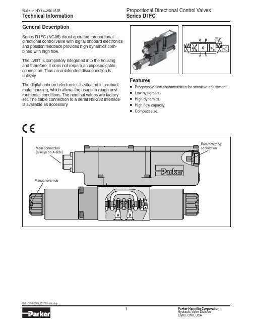
Series D1FCGeneral DescriptionSeries D1FC (NG06) direct operated, proportionaldirectional control valve with digital onboard electronics and position feedback provides high dynamics com-bined with high flow.The LVDT is completely integrated into the housing and therefore, it does not require an exposed cable connection. Thus an unintended disconnection is unlikely.The digital onboard electronics is situated in a robust metal housing, which allows the usage in rough envi-ronmental conditions. The nominal values are factory set. The cable connection to a serial RS-232 interfaceis available as accessory.Features• Progressive flow characteristics for sensitive adjustment.• Low hysteresis.• High dynamics.• High flow capacity.• Compact size.Technical InformationSeries D1FCDirectional Flow Size1Spool CInput SignalDrain Port Y Plugged*9SealDFHigh CDesign Series NOTE: Not required when ordering.Code Description06+PE acc. EN175201-804511+PE acc. EN175201-80476+PE + Enable acc. EN175201-804Code DescriptionN NitrileV FluorocarbonCode SignalFunction B 0...±10V 0...+10V P -> A E 0...±20mA 0...+20mA P -> A S4...20mA12...20mA P -> AElectronic Options Weight:D1FC3.4 kg (7.5 lbs.)Bolt Kit:BK209 (4) 10-24x1.25 SHCS BK375 (4) M5x30Please order connector separately. See Accessories.Parametrizing cable OBE => RS-232 Item no. 40982923* Needs to be removed at tank pressure >35 Bar (507.5 PSI).Spool/ Body Design3Ordering InformationSeries D1FC1)If valves with onboard electronics are used in safety-related parts of control systems, in case the safety function is requested, the valve electronics voltage supply is to be switched off by a suitable switching element with sufficient reliability. 2)Flow rate for different ∆p per control edge:3)Measured with load 210 Bar (3045 PSI) pressure drop; two control edges.Q x = Q Nom. · √∆p x ∆p Nom.SpecificationsSeries D1FC100755025P-B Spool Type E*P-A100-80-60-40-20204060801000F l o w (Q ) % o f N o m i n a l F l o wInput Signal (%)%at p = 5 Bar (72.5 PSI) per metering edgeA-T P-B Spool Type B*B-T100755025%100-80-60-40-20204060801000F l o w (Q ) % o f N o m i n a l F l o wInput Signal (%)P-Aatp = 5 Bar (72.5 PSI) per metering edgeFunctional limits25%, 50%, 75% and 100% command signal (symmetric flow). At asymmetric flow a reduced flow limit has to be considered.All characteristic curves measured with HLP46 at 50 °C.(Electronically set to opening point 10%)Spool type B31/32Spool Type E01/02Performance CurvesSeries D1FCCode 06 + PE acc. EN 175201-804Code 511 + PE acc. EN 175201-804Code 76 + PE acc. EN 175201-804 + EnableWiring ConnectionsSeries D1FC Interface Program Features• Simple editing of all parameters.• Storage and loading of optimized parameter adjustments.• Executable with all Windows ®operating systems fromWindows ®95 upwards.• Communication between PC and electronics via serialinterface RS-232.The valve electronics cannot be connected to a PC with a standard USB cable – this can result in damages of PC and/or valve electronics.Simple to use interface program. Download free of charge /euro_hcd → Services → downloadsProPxD Interface ProgramThe ProPxD software allows quick and easy setting of the digital valve electronics. Individual parameters as well as complete settings can be viewed, changed and saved via the comfortable user interface. Parameter sets saved in the non-volatile memory can be loaded to other valves of the same type or printed out fordocumentation purposes.The parametrizing cable may be ordered under item no. 40982923.Series D1FCInch equivalents for millimeter dimensions are shown in (**)Port Y pluggedRemove and use Y Port if tank pressure > 35 Bar (507 PSI)DimensionsParker Hannifin Corporation Hydraulic Valve Division 520 Ternes AvenueElyria, Ohio 44035 USA Tel: 440 366 5100Bulletin HY14-2561/US,7/15© 2015 Parker Hannifin Corporation. All rights reserved.FAILURE OR IMPROPER SELECTION OR IMPROPER USE OF THE PRODUCTS DESCRIBED HEREIN OR RELA TED ITEMS CAN CAUSE DEA TH, PERSONAL INJURY AND PROPERTY DAMAGE.• This document and other information from Parker-Hannifin Corporation, its subsidiaries and authorized distributors provide product or system options for further investigation by users having technical expertise.• The user, through its own analysis and testing, is solely responsible for making the final selection of the system and components and assuring that all performance, endurance, maintenance, safety and warning requirements of the application are met. The user must analyze all aspects of the application, follow applicable industry standards, and follow the information concerning the product in the current product catalog and in any other materials provided from Parker or its subsidiaries or authorized distributors.• T o the extent that Parker or its subsidiaries or authorized distributors provide component or system options based upon data or specifications provided by the user, the user is responsible for determining that such data and specifications are suitable and sufficient for all applications and reasonably foreseeable uses of the components or systems.WARNING – USER RESPONSIBILITYThe items described in this document are hereby offered for sale by Parker-Hannifin Corporation, its subsidiaries or its authorized distributors. This offer and its acceptance are governed by the provisions stated in the detailed “Offer of Sale” elsewhere in this document or available at /hydraulicvalve.OFFER OF SALEFor safety information, see Safety Guide SG HY14-1000 at /safety or call 1-800-CParker.SAFETY GUIDE。
任氏3331电导率 电阻率变送器使用说明书

使用说明书MODEL 3331微电脑电导率/电阻率变送器JENCO ELECTRONICS, LTD.上海任氏电子有限公司目录简介 (2)产品检视 (2)MODEL 3331的使用 (3)A. 安装步骤 (3)B. 前面板及按键说明 (5)C. 显示 (8)D. 端子接线图 (10)E. 测量模式 (11)F. 设定模式 (12)G. 电导率/ 电阻率校正模式 (19)H. 继电器控制 (19)错误显示及原因 (21)规格 (23)质量保证 (25)- 1 -感谢您选用JENCO Model 3331,Model 3331电导率/电阻率变送器是使用单芯片微电脑设计的测试及变送器,它是包装在 1/8 DIN 的外壳里,使用于实验室与各种控制场所。
Model 3321可显示电导率、电阻率或者温度。
每次开机,整机的微处理器就会执行一次自我诊断。
该变送器具备一路隔离电流输出,其输出范围可由使用者自行设定。
小心地打开包装,检视仪器及配件是否有因运送而损坏,如有发现损坏,请即刻通知任氏的代理商,并以原包装寄回送检。
- 2 -RVIEW A. 安装步骤图一1. 在厚度1/16英寸(1.5mm)~3/8英寸(9.5mm)的安装板上开一个大小如左图的方孔。
见图一。
图二2. 先拆下固定支架,将机器放入刚开的方孔内。
见图二。
.- 3 -安装板 固定支架图三3. 装上支架,并将支架往前推紧,确保机器固定在安装板上。
见图三。
【注意】:如果不按以上方式安装仪表,可能致使仪表受到损害。
- 4 -B. 前面板及按键说明整机的显示板拥有一个四位LCD显示以及四个机械式开关。
1. [ MODE ] 键:1a. 在测量模式,按此键依次循环显示电导率值和温度值或者电阻率值和温度值。
1b. 在设定模式,按住此键三秒,整机将退回上一个设定参数。
2. [ UP ] 键:2a. 在校正模式,按此键将显示上一个校正项目。
在设定模式,按此键将显示上一个设定项目或者增加设定项目的数值。
Z1 配置福尼斯焊机的机器人系统参数设置说明

配置福尼斯焊机的机器人系统参数设置说明吴为进2011-10 一、检查系统配置,确认ARC选项为:650-9 Fronius TPS4000/5000ABB出厂默认选项,如果使用旧机器人ARC选项可能不是650-9 Fronius TPS4000/5000,需重装系统,参考系统安装手册。
二、修改EIO.cfg,配置肯比焊机信号2.1、EIO_UNIT_TYPE确认福尼斯焊机通讯板定义;如果没有定义,添加如下定义。
-Name "BK5200" -BusType "DNET" -VendorName "BECKHOFF"\-ProductName "BECKHOFF" -DN_VendorId 108 -DN_ProductCode 5200\-DN_DeviceType 12 -DN_MajorRev 3 -DN_C1Interval 30 -DN_C1OutputSize -1\-DN_C1InputSize -1-Name "BK5250" -BusType "DNET" -VendorName "BECKHOFF"\-ProductName "BECKHOFF" -DN_VendorId 108 -DN_ProductCode 5250\-DN_DeviceType 12 -DN_C1Interval 30 -DN_C1OutputSize -1 -DN_C1InputSize -12.2、EIO_UNIT添加福尼斯焊机通讯板及虚拟板;红字的“20”为DeviceNet 地址需根据福尼斯的拔码开关确定,不能与系统中已使用的地址重复。
-Name "ioFronius1" -UnitType "BK5250" -Bus "DeviceNet1" -DN_Address 20-Name "ioFroniusSim1" -UnitType "Virtual" -Bus "Virtual1"\-UnitLabel "RWArc Simulated welder"2.3、EIO_SIGNAL添加如下信号,所有信号不能修改;-Name "doFr1ArcOn" -SignalType "DO" -Unit "ioFronius1" -UnitMap "0"-Name "doFr1RobotReady" -SignalType "DO" -Unit "ioFronius1" -UnitMap "1"-Name "doFr1GasTest" -SignalType "DO" -Unit "ioFronius1" -UnitMap "8"-Name "doFr1FeedForward" -SignalType "DO" -Unit "ioFronius1" -UnitMap "9"-Name "doFr1FeedRetract" -SignalType "DO" -Unit "ioFronius1" -UnitMap "10"-Name "doFr1ErrorReset" -SignalType "DO" -Unit "ioFronius1" -UnitMap "11"-Name "doFr1TouchSense" -SignalType "DO" -Unit "ioFronius1" -UnitMap "12"-Name "doFr1TrchBlowOut" -SignalType "DO" -Unit "ioFronius1" -UnitMap "13"-Name "doFr1WeldingSim" -SignalType "DO" -Unit "ioFronius1" -UnitMap "31"-Name "diFr1ArcStable" -SignalType "DI" -Unit "ioFronius1" -UnitMap "0"\-FiltPas 50-Name "diFr1ProcessActv" -SignalType "DI" -Unit "ioFronius1" -UnitMap "2"-Name "diFr1MainCurrent" -SignalType "DI" -Unit "ioFronius1" -UnitMap "3"-Name "diFr1TorchColisn" -SignalType "DI" -Unit "ioFronius1" -UnitMap "4"-Name "diFr1WelderReady" -SignalType "DI" -Unit "ioFronius1" -UnitMap "5"-Name "diFr1CommunicRdy" -SignalType "DI" -Unit "ioFronius1" -UnitMap "6"-Name "aoFr1Power" -SignalType "AO" -Unit "ioFronius1" -UnitMap "32-47"\-EncType "UNSIGNED" -MaxLog 100 -MaxPhys 10 -MaxPhysLimit 10\-MaxBitVal 65535-Name "aoFr1ArcLength" -SignalType "AO" -Unit "ioFronius1"\-UnitMap "48-63" -EncType "UNSIGNED" -MaxLog 30 -MaxPhys 10\-MaxPhysLimit 10 -MaxBitVal 65535 -MinLog -30-Name "aoFr1Dynamic" -SignalType "AO" -Unit "ioFronius1" -UnitMap "64-71"\-EncType "UNSIGNED" -MaxLog 5 -MaxPhys 10 -MaxPhysLimit 10 -MaxBitVal 255\ -MinLog -5-Name "aoFr1BurnBackCor" -SignalType "AO" -Unit "ioFronius1"\-UnitMap "72-79" -EncType "UNSIGNED" -MaxLog 200 -MaxPhys 10\-MaxPhysLimit 10 -MaxBitVal 255 -MinLog -200-Name "aiFr1V olt_M" -SignalType "AI" -Unit "ioFronius1" -UnitMap "32-47"\-EncType "UNSIGNED" -MaxLog 100 -MaxPhys 10 -MaxPhysLimit 10\-MaxBitVal 65535-Name "aiFr1Current_M" -SignalType "AI" -Unit "ioFronius1"\-UnitMap "48-63" -EncType "UNSIGNED" -MaxLog 1000 -MaxPhys 10\-MaxPhysLimit 10 -MaxBitVal 65535-Name "aiFr1MotorCurr_M" -SignalType "AI" -Unit "ioFronius1"\-UnitMap "64-71" -EncType "UNSIGNED" -MaxLog 5 -MaxPhys 10\-MaxPhysLimit 10 -MaxBitVal 255-Name "aiFr1WireFeed_M" -SignalType "AI" -Unit "ioFronius1"\-UnitMap "80-95" -EncType "UNSIGNED" -MaxLog 366.67 -MaxPhys 10\-MaxPhysLimit 10 -MaxBitVal 65535-Name "goFr1Mode" -SignalType "GO" -Unit "ioFronius1" -UnitMap "2-4"-Name "goFr1JobNum" -SignalType "GO" -Unit "ioFronius1" -UnitMap "16-23"-Name "goFr1PrgNum" -SignalType "GO" -Unit "ioFronius1" -UnitMap "24-30"-Name "giFr1Error" -SignalType "GI" -Unit "ioFronius1" -UnitMap "8-15"-Name "siFr1WelderOK" -SignalType "DI" -Unit "ioFroniusSim1" -UnitMap "0"-Name "soFr1WelderOK" -SignalType "DO" -Unit "ioFroniusSim1" -UnitMap "0"-Name "siFr1StopProc" -SignalType "DI" -Unit "ioFroniusSim1" -UnitMap "1"-Name "soFr1StopProc" -SignalType "DO" -Unit "ioFroniusSim1" -UnitMap "1"\-Access "ALL"-Name "siFr1WireStick" -SignalType "DI" -Unit "ioFroniusSim1" -UnitMap "2"-Name "soFr1WireStick" -SignalType "DO" -Unit "ioFroniusSim1" -UnitMap "2"-Name "soFr1UpdateSched" -SignalType "DO" -Unit "ioFroniusSim1"\-UnitMap "3"-Name "diFr1PartDetect" -SignalType "DI" -Unit "ioFroniusSim1"\-UnitMap "4"-Name "doFr1SensorRef" -SignalType "DO" -Unit "ioFroniusSim1" -UnitMap "4"-Name "soFr1ArcOn" -SignalType "DO" -Unit "ioFroniusSim1" -UnitMap "5"2.4、添加电弧反馈虚拟信号,解决跟踪路径不保存问题。
三菱电机 第4代大型DIPIPM 应用手册

三菱电机株式会社和三菱电机机电(上海)有限公司拥有本手册内所有资料的版权。 任何个人和企业在未得到书面许可的情况下,不得传播、复制、转载、出版和出售涉及本手册的任何内 容。如有违反,我们将保留追究其法律责任的权利。敬请留意。
2009 年 3 月
第 4 代大型 DIPIPM 应用手册
目录
第 1 章 产品概要 ......................................................................................................................................... 1
2.2 保护功能及其工作时序.......................................................................................................................... 9 2.2.1 短路保护......................................................................................................................................... 9 2.2.2 控制电源欠压保护(UV) ..................................................................................................... 12 2.2.............................................................................................. 13
三相交流电动机保护器AMDTH-X E01□系列使用说明书
AMDTH-X/E01□ 系列电动机保护器使用说明产品概述主要特点:DSP 为核心,数字设定,数字显示,保护功能完备、保护性能可靠,检测零序电流,通用电流互感器检测电流。
保护功能:缺相、短路、接地、堵转、过载、电流不平衡、零序。
适用范围:额定电压不高于1140V,50Hz或60Hz,起动负载重、起动时间长的三相交流电动机。
电流互感器一次电流(A)100 150 200300400500600800 1000 12001600最大设定电流(A) 65 98 130195260325390520 650 7801040最小设定电流(A) 20 30 40 60 80 100120160 200 240320电动机最大功率(KW) 30 45 55 90 132160185250 315 355500电动机最小功率(KW) 11 15 22 30 45 55 75 90 110 132160工作电压:AC 85V — 265V、DC 85V — 265V功率消耗:小于 2W采集精度:0.5环境温度:- 20℃ — 50℃继电器触点:AMDTH-X/E011:1常开、常闭触点,AC 250V/10A(阻性负载)、DC 30V/10AAMDTH-X/E013:独立2常开触点,AC 220V/5A(阻性负载)、DC 30V/5AAMDTH-X/E014:独立1常开、1常闭触点,AC 220V/5A(阻性负载)、DC 30V/5A零序电流输入阻抗:小于 1 ΩAMDTH-X/E01□系列电动机保护器数据显示AMDTH-X/E01□ 系列电动机保护器在电动机正常运行时,显示电动机A、B、C相电流、零序电流;当电动机发生缺相、短路、接地、堵转、过载、电流不平衡、零序故障时,断开内部继电器触点停止电动机运行(故障灯亮),同时显示故障代码指Array示故障类型,并且显示电动机发生故障时的A、B、C相电流、零序电流值。
施耐德主令控制器
产品目录
目录
介绍........................................................................................................... 2 选型指南.................................................................................................. 4 术语名词.................................................................................................. 6 轻型主令控制器XKB............................................................................ 8 中型主令控制器XKD.......................................................................... 16 重型主令控制器XKM .........................................................................24 主令控制器XKB,XKD,XKM尺寸 ................................................38 电位器及支架.......................................................................................42 XKD编码器用户手册......................................................................... 44 XKD编码器安装指导......................................................................... 46
- 1、下载文档前请自行甄别文档内容的完整性,平台不提供额外的编辑、内容补充、找答案等附加服务。
- 2、"仅部分预览"的文档,不可在线预览部分如存在完整性等问题,可反馈申请退款(可完整预览的文档不适用该条件!)。
- 3、如文档侵犯您的权益,请联系客服反馈,我们会尽快为您处理(人工客服工作时间:9:00-18:30)。
Photodiode
FEATURES
• High Quantum Efficiency: 0.8A/W at 1,310nm
•Low dark current: 0.1nA
• Photosensitive area: 50µm diameter
• Wide spectral response range: 900nm to 1,600nm
APPLICATIONS
• Optical transmission system: STM-1 (OC-3),
STM-4 (OC-12) or STM-16 (OC-48) short haul.
DESCRIPTION
fiber pigtail designed for use in local area network, subscriber at both 1,310nm and 1,550nm wavelength. The PIN chip has a guard ring for high reliability. A multimode fiber is aligned to the high coupling stability.
Edition 1.0
ABSOLUTE MAXIMUM RATINGS (T=25°C)
OPTICAL & ELECTRICAL CHARACTERISTICS (T=-40 to +85°C, λ=1,310/1,550nm unless otherwise specified)
Note 1: Optical characteristics are specified on the condition that single mode fiber is used as the
optical source for testing.
Photodiode
Fig. 1 Spectral Response (η vs. λ)
Fig. 2 Spectral Response (R vs.λ)
N o r m a l i z e d R e s p o n s i v i t y , ∆R /R (25°C ) (%)
Q u a n t u m E f f i c i e n c y , η (%)
6040100
20080
10
20
Reverse Voltage, V R (V)
T a = 25°C Fig. 7 Capacitance vs. Reverse Voltage Fig. 6 Frequency Response
R e s p o n s e (d B )
2
-9
-12
-6-3010
102103
Fig. 5 Dark Current vs. Temperature
D a r k C u r r e n t , I D (A )
-20
20
406080
-4010-11
10-1210-9
10-810-13
10-10Temperature, Ta (°C)
Frequency (MHz)
V R =5V
V R =5V R L = 50Ωλ = 1,310nm
10550
0.50.2
1Reverse Voltage, V R (V)
C a p a c i t a n c e , C t (p F )
1
0.110
T a =25°C
f=1 MHz
Photodiode
Fujitsu Limited reserves the right to change products and specifications without notice.The information does not convey any license under rights of Fujitsu Limited or others.
©1999 FUJITSU COMPOUND SEMICONDUCTOR, INC.Printed in U.S.A. FCSI0199M200
Fujitsu Compound Semiconductor Products contain gallium arsenide (GaAs) which can be hazardous to the human body and the environment. For safety, observe the following procedures:
CAUTION
• Do not put this product into the mouth.
• Do not alter the form of this product into a gas, powder, or liquid
through burning, crushing, or chemical processing as these by-products are dangerous to the human body if inhaled, ingested, or swallowed.• Observe government laws and company regulations when discarding this product. This product must be discarded in accordance with methods specified by applicable hazardous waste procedures.
For further information please contact:
FUJITSU COMPOUND SEMICONDUCTOR, INC.
2355 Zanker Rd.
San Jose, CA 95131-1138, U.S.A.Phone: (408) 232-9500FAX: (408) 428-9111
FUJITSU QUANTUM DEVICES EUROPE LTD.
Network House Norreys Drive
Maidenhead, Berkshire SL6 4FJ United Kingdom
TEL: +44 (0) 1628 504800FAX: +44 (0) 1628 504888
FUJITSU QUANTUM DEVICES SINGAPORE PTE LTD.Hong Kong Branch
Rm. 1101, Ocean Centre, 5 Canton Rd. Tsim Sha Tsui,Kowloon, Hong Kong TEL: +852-********FAX: +852-********
FUJITSU QUANTUM DEVICES LIMITED
Business Development Division
11th Floor, Hachioji Daiichi-Seimei Bldg.3-20-6 Myojin-cho
Hachioji-city, Tokyo 192-0046, Japan TEL: +81-426-43-5885FAX: +81-426-43-5582。