MAX6382XR29D5+中文资料
MAX2990中文资料
传感器控制和数据采集 电力线传输语音设备
Key Specifications: Powerline Networking Devices
Part Features
Number
Security Features
Smalles
t
Budgetary
Availabl Oper. Interf EV Package e Pckg. Temp.
MAX2990
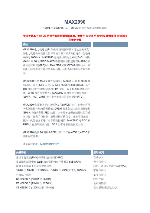
10kHz 至 490kHz、基于 OFDM 的电力线通信调制解调器
业内首款基于 OFDM 的电力线通信调制解调器,能够在 10kHz 至 490kHz 频带提供 100kbps 的数据传输
概述
MAX2990 电力线通信(PLC)基带调制解调器可通过交流或直 流电力线提供高性价比且可靠的半双工异步数据通信,传输速 率高达 100kbps。MAX2990 是高集成度片上系统(SoC),利用 Maxim 的 16 位 RISC MAXQ 微控制器核构建物理层(PHY)和 媒体访问控制(MAC)层。MAX2990 采用 OFDM 调制技术,可 在电力网络中进行稳定的数据传输,同时为网络的所有器件供 电。
Yes LQFP/64
Compliant to
Serial
Managemen
FCC,
UART
t
CENELEC,
148.8
-40 to $8.50 @1k
+85
ARIB
Data Rate Up
to 100Kbps
OFDM-Based
PHY
查看所有 Powerline Networking Devices (5)
Pricing Notes:
This pricing is BUDGETARY, for comparing similar parts. Prices are in U.S. dollars and subject to change. Quantity pricing may vary substantially and international prices may differ due to local duties, taxes, fees, and exchange rates. For volume-specific prices and delivery, please see the price and availability page or contact an authorized distributor.
MAX6387XS33D7-T中文资料

General DescriptionThe MAX6381–MAX6390 microprocessor (µP) supervisory circuits monitor power supply voltages from +1.8V to +5.0V while consuming only 3µA of supply current at +1.8V. Whenever V CC falls below the factory-set reset thresholds, the reset output asserts and remains assert-ed for a minimum reset timeout period after V CC rises above the reset threshold. Reset thresholds are available from +1.58V to +4.63V, in approximately 100mV incre-ments. Seven minimum reset timeout delays ranging from 1ms to 1200ms are available.The MAX6381/MAX6384/MAX6387 have a push-pull active-low reset output. The MAX6382/MAX6385/MAX6388 have a push-pull active-high reset output,and the MAX6383/MAX6386/MAX6389/MAX6390 have an open-drain active-low reset output. The MAX6384/MAX6385/MAX6386 also feature a debounced manual reset input (with internal pullup resistor). The MAX6387/MAX6388/MAX6389 have an auxiliary input for monitoring a second voltage. The MAX6390 offers a manual reset input with a longer V CC reset timeout period (1120ms or 1200ms) and a shorter manual reset timeout (140ms or 150ms).The MAX6381/MAX6382/MAX6383 are available in 3-pin SC70 packages and the MAX6384–MAX6390 are avail-able in 4-pin SC70 packages.________________________ApplicationsComputers ControllersIntelligent InstrumentsCritical µP and µC Power Monitoring Portable/Battery-Powered Equipment Dual Voltage SystemsFeatureso Factory-Set Reset Threshold Voltages Ranging from +1.58V to +4.63V in Approximately 100mV Increments o ±2.5% Reset Threshold Accuracy Over Temperature (-40°C to +125°C)o Seven Reset Timeout Periods Available: 1ms,20ms, 140ms, 280ms, 560ms, 1120ms, 1200ms (min)o 3 Reset Output OptionsActive-Low Push-Pull Active-High Push-Pull Active-Low Open-Draino Reset Output State Guaranteed Valid Down to V CC = 1Vo Manual Reset Input (MAX6384/MAX6385/MAX6386)o Auxiliary RESET IN(MAX6387/MAX6388/MAX6389)o V CC Reset Timeout (1120ms or 1200ms)/Manual Reset Timeout (140ms or 150ms) (MAX6390)o Negative-Going V CC Transient Immunity o Low Power Consumption of 6µA at +3.6V and 3µA at +1.8V o Pin Compatible withMAX809/MAX810/MAX803/MAX6326/MAX6327/MAX6328/MAX6346/MAX6347/MAX6348, and MAX6711/MAX6712/MAX6713o Tiny 3-Pin SC70 and 4-Pin SC70 PackagesMAX6381–MAX6390SC70, Single/Dual Low-Voltage, Low-Power µP Reset Circuits________________________________________________________________Maxim Integrated Products1Pin Configurations19-1839; Rev 1; 04/01Ordering InformationOrdering Information continued at end of data sheet.Typical Operating Circuit appears at end of data sheet.Selector Guide appears at end of data sheet.Note:Insert reset threshold suffix (see Reset Threshold table)after "XR" or "XS". Insert reset timeout delay (see Reset Timeout Delay table) after "D" to complete the part number. Sample stock is generally held on standard versions only (seeStandard Versions table). Standard versions have an order increment requirement of 2500 pieces. Nonstandard versions have an order increment requirement of 10,000 pieces.Contact factory for availability of nonstandard versions.*MAX6390 is available with D4 or D7 timing only.For pricing, delivery, and ordering information,please contact Maxim/Dallas Direct!at 1-888-629-4642, or visit Maxim’s website at .M A X 6381–M A X 6390SC70, Single/Dual Low-Voltage, Low-Power µP Reset CircuitsABSOLUTE MAXIMUM RATINGSELECTRICAL CHARACTERISTICSStresses beyond those listed under “Absolute Maximum Ratings” may cause permanent damage to the device. These are stress ratings only, and functional operation of the device at these or any other conditions beyond those indicated in the operational sections of the specifications is not implied. Exposure to absolute maximum rating conditions for extended periods may affect device reliability.V CC to GND..........................................................-0.3V to +6.0V RESET Open-Drain Output....................................-0.3V to +6.0V RESET , RESET (Push-Pull Output).............-0.3V to (V CC + 0.3V)MR , RESET IN.............................................-0.3V to (V CC + 0.3V)Input Current (V CC ).............................................................20mA Output Current (All Pins).....................................................20mAContinuous Power Dissipation (T A = +70°C)3-Pin SC70 (derate 2.9mW/°C above +70°C)........235mW 4-Pin SC70 (derate 3.1mW/°C above +70°C)........245mW Operating Temperature Range .........................-40°C to +125°C Storage Temperature Range.............................-65°C to +150°C Lead Temperature (soldering, 10s).................................+300°CMAX6381–MAX6390SC70, Single/Dual Low-Voltage, Low-Power µP Reset Circuits_______________________________________________________________________________________3M A X 6381–M A X 6390SC70, Single/Dual Low-Voltage, Low-Power µP Reset Circuits 4______________________________________________________________________________________Typical Operating Characteristics(T A = +25°C, unless otherwise noted.)215436789-40-105-25203550658095110125SUPPLY CURRENT vs. TEMPERATURE(NO LOAD)TEMPERATURE (°C)S U P P L Y C U R R E N T (µA )25292735333137394143-40-105-25203550658095110125POWER-DOWN RESET DELAYvs. TEMPERATURETEMPERATURE (°C)P O W E R -D O W N R E S E T D E L A Y (µs )0.940.980.961.021.001.061.041.08-40-10520-253550658095110125NORMALIZED POWER-UP RESET TIMEOUTvs. TEMPERATUREM A X 6381/90 t o c 03TEMPERATURE (°C)N O R M A L I Z E D R E S E T T I M E O U T P E R I O D0.9900.9851.0150.9950.9901.0001.0051.0101.020-40-10520-253550958011065125M A X 6381/90 t o c 04TEMPERATURE (°C)N O R M A L I Z E D R E S E TT H R E S H O L D NORMALIZED RESET THRESHOLDvs. TEMPERATURE00.40.20.80.61.01.2063912OUTPUT VOLTAGE LOW vs. SINK CURRENTI SINK (mA)V O L (V )01.00.52.01.52.53.00500750250100012501500OUTPUT VOLTAGE HIGH vs. SOURCE CURRENTI SOURCE (µA)V O H (V )45001100010010MAXIMUM TRANSIENT DURATION vs. RESET COMPARATOR OVERDRIVE15050350250500200100400300RESET COMPARATOR OVERDRIVE, V TH - V CC (mV)M A X I M U M T R A N S I E N T D U R A T I O N (µs )3.53.93.74.54.34.14.74.95.35.15.5-40-105-25203550658095110125RESET IN TO RESET DELAYvs. TEMPERATUREM A X 6381/90 t o c 08TEMPERATURE (°C)R E S E T I N D E L A Y (µs )MAX6381–MAX6390SC70, Single/Dual Low-Voltage, Low-Power µP Reset Circuits_______________________________________________________________________________________5M A X 6381–M A X 6390SC70, Single/Dual Low-Voltage, Low-Power µP Reset Circuits 6_______________________________________________________________________________________Detailed DescriptionRESET OutputA µP reset input starts the µP in a known state. These µP supervisory circuits assert reset to prevent code execution errors during power-up, power-down, or brownout conditions.Reset asserts when V CC is below the reset threshold;once V CC exceeds the reset threshold, an internal timer keeps the reset output asserted for the reset timeout period. After this interval, reset output deasserts. Reset output is guaranteed to be in the correct logic state for V CC ≥1V.Manual Reset Input (MAX6384/MAX6385/MAX6386/MAX6390)Many µP-based products require manual reset capabil-ity, allowing the operator, a test technician, or external logic circuitry to initiate a reset. A logic low on MR asserts reset. Reset remains asserted while MR is low,and for the reset active timeout period (t RP ) after MR returns high. This input has an internal 63k Ωpullup resistor (1.35k Ωfor MAX6390), so it can be left uncon-nected if it is not used. MR can be driven with TTL or CMOS logic levels, or with open-drain/collector outputs.Connect a normally open momentary switch from MR to G ND to create a manual-reset function; external debounce circuitry is not required. If MR is driven from long cables or if the device is used in a noisy environ-ment, connecting a 0.1µF capacitor from MR to G ND provides additional noise immunity.RESET IN Comparator(MAX6387/MAX6388/MAX6389)RESET IN is compared to an internal +1.27V reference.If the voltage at RESET IN is less than 1.27V, reset asserts. Use the RESET IN comparator as a user-adjustable reset detector or as a secondary power-sup-ply monitor by implementing a resistor-divider at RESET IN (shown in Figure 1). Reset asserts when either V CC or RESET IN falls below its respective threshold volt-age. Use the following equation to set the threshold:V INTH = V THRST (R1/R2 + 1)where V THRST = +1.27V. To simplify the resistor selec-tion, choose a value of R2 and calculate R1:R1 = R2 [(V INTH /V THRST ) - 1]Since the input current at RESET IN is 50nA (max),large values can be used for R2 with no significant loss in accuracy.___________Applications InformationNegative-Going V CC TransientsIn addition to issuing a reset to the µP during power-up,power-down, and brownout conditions, the MAX6381–MAX6390 are relatively immune to short dura-tion negative-going V CC transients (glitches).The Typical Operating Characteristics section shows the Maximum Transient Durations vs. Reset Comparator Overdrive, for which the MAX6381–MAX6390 do not generate a reset pulse. This graph was generated usinga negative-going pulse applied to V CC , starting above the actual reset threshold and ending below it by the magni-tude indicated (reset comparator overdrive). The graph indicates the typical maximum pulse width a negative-going V CC transient may have without causing a reset pulse to be issued. As the magnitude of the transient increases (goes farther below the reset threshold), the maximum allowable pulse width decreases. A 0.1µF capacitor mounted as close as possible to V CC provides additional transient immunity.Ensuring a Valid RESET Output Down to V CC = 0The MAX6381–MAX6390 are guaranteed to operate properly down to V CC = 1V. In applications that require valid reset levels down to V CC = 0, a pulldown resistor to active-low outputs (push/pull only, Figure 2) and a pullup resistor to active-high outputs (push/pull only) will ensure that the reset line is valid while the reset output can no longer sink or source current. This scheme doesnot work with the open-drain outputs of the MAX6383/MAX6386/MAX6389/MAX6390. The resistor value used is not critical, but it must be small enough not to load the reset output when V CC is above the reset threshold. For most applications, 100k Ωis adequate.MAX6381–MAX6390SC70, Single/Dual Low-Voltage, Low-Power µP Reset Circuits_______________________________________________________________________________________7M A X 6381–M A X 6390SC70, Single/Dual Low-Voltage, Low-Power µP Reset Circuits 8Selector GuideChip InformationTRANSISTOR COUNT: 647PROCESS: BiCMOS*MR is for MAX6384/MAX6385/MAX6386/MAX6390**RESET IN is for MAX6387/MAX6388/MAX6389( ) are for MAX6382/MAX6385/MAX6388Pin Configurations (continued)MAX6381–MAX6390SC70, Single/Dual Low-Voltage, Low-Power µP Reset Circuits_______________________________________________________________________________________9Ordering Information(continued)Note:Insert reset threshold suffix (see Reset Threshold table)after "XR" or "XS". Insert reset timeout delay (see Reset Timeout Delay table) after "D" to complete the part number. Sample stock is generally held on standard versions only (seeStandard Versions table). Standard versions have an order increment requirement of 2500 pieces. Nonstandard versions have an order increment requirement of 10,000 pieces.Contact factory for availability of nonstandard versions.*MAX6390 is available with D4 or D7 timing only.M A X 6381–M A X 6390SC70, Single/Dual Low-Voltage, Low-Power µP Reset Circuits 10______________________________________________________________________________________Package InformationSC70, Single/Dual Low-Voltage, Low-Power µP Reset CircuitsMaxim cannot assume responsibility for use of any circuitry other than circuitry entirely embodied in a Maxim product. No circuit patent licenses are implied. Maxim reserves the right to change the circuitry and specifications without notice at any time.Maxim Integrated Products, 120 San Gabriel Drive, Sunnyvale, CA 94086 408-737-7600____________________11©2001 Maxim Integrated Products Printed USA is a registered trademark of Maxim Integrated Products.MAX6381–MAX6390Package Information (continued)元器件交易网。
MAX3232中文资料zhuanzai

MAX3222/MAX3232/MAX3237/MAX32413.0V至5.5V、低功耗、1Mbps、真RS-232收发器,使用四只0.1µF外部电容________________________________________________________________Maxim Integrated Products119-0273; Rev 7; 1/07MegaBaud和UCSP是Maxim Integrated Products, Inc.的商标。
本页已使用福昕阅读器进行编辑。
M A X 3222/M A X 3232/M A X 3237/M A X 32413.0V至5.5V、低功耗、1Mbps、真RS-232收发器,使用四只0.1µF外部电容2_______________________________________________________________________________________ABSOLUTE MAXIMUM RATINGSELECTRICAL CHARACTERISTICS(V CC = +3.0V to +5.5V, C1–C4 = 0.1µF (Note 2), T A = T MIN to T MAX , unless otherwise noted. Typical values are at T A = +25°C.)Stresses beyond those listed under “Absolute Maximum Ratings” may cause permanent damage to the device. These are stress ratings only, and functional operation of the device at these or any other conditions beyond those indicated in the operational sections of the specifications is not implied. Exposure to absolute maximum rating conditions for extended periods may affect device reliability.Note 1:V+ and V- can have a maximum magnitude of 7V, but their absolute difference cannot exceed 13V.V CC ...........................................................................-0.3V to +6V V+ (Note 1)...............................................................-0.3V to +7V V- (Note 1)................................................................+0.3V to -7V V+ + V- (Note 1)...................................................................+13V Input VoltagesT_IN, SHDN , EN ...................................................-0.3V to +6V MBAUD...................................................-0.3V to (V CC + 0.3V)R_IN.................................................................................±25V Output VoltagesT_OUT...........................................................................±13.2V R_OUT....................................................-0.3V to (V CC + 0.3V)Short-Circuit DurationT_OUT....................................................................ContinuousContinuous Power Dissipation (T A = +70°C)16-Pin TSSOP (derate 6.7mW/°C above +70°C).............533mW 16-Pin Narrow SO (derate 8.70mW/°C above +70°C)....696mW 16-Pin Wide SO (derate 9.52mW/°C above +70°C)........762mW 16-Pin Plastic DIP (derate 10.53mW/°C above +70°C)...842mW 18-Pin SO (derate 9.52mW/°C above +70°C)..............762mW 18-Pin Plastic DIP (derate 11.11mW/°C above +70°C)..889mW 20-Pin SSOP (derate 7.00mW/°C above +70°C).........559mW 20-Pin TSSOP (derate 8.0mW/°C above +70°C).............640mW 28-Pin TSSOP (derate 8.7mW/°C above +70°C).............696mW 28-Pin SSOP (derate 9.52mW/°C above +70°C).........762mW 28-Pin SO (derate 12.50mW/°C above +70°C).....................1W Operating Temperature RangesMAX32_ _C_ _.....................................................0°C to +70°C MAX32_ _E_ _ .................................................-40°C to +85°C Storage Temperature Range.............................-65°C to +150°C Lead Temperature (soldering, 10s).................................+300°CMAX3222/MAX3232/MAX3237/MAX32413.0V至5.5V、低功耗、1Mbps、真RS-232收发器,使用四只0.1µF外部电容_______________________________________________________________________________________3TIMING CHARACTERISTICS—MAX3222/MAX3232/MAX3241(V CC = +3.0V to +5.5V, C1–C4 = 0.1µF (Note 2), T A = T MIN to T MAX , unless otherwise noted. Typical values are at T A = +25°C.)ELECTRICAL CHARACTERISTICS (continued)(V CC = +3.0V to +5.5V, C1–C4 = 0.1µF (Note 2), T A = T MIN to T MAX , unless otherwise noted. Typical values are at T A = +25°C.)M A X 3222/M A X 3232/M A X 3237/M A X 32413.0V至5.5V、低功耗、1Mbps、真RS-232收发器,使用四只0.1µF外部电容4________________________________________________________________________________________________________________________________________________________________典型工作特性(V CC = +3.3V, 235kbps data rate, 0.1µF capacitors, all transmitters loaded with 3k Ω, T A = +25°C, unless otherwise noted.)-6-5-4-3-2-101234560MAX3222/MAX3232TRANSMITTER OUTPUT VOLTAGEvs. LOAD CAPACITANCELOAD CAPACITANCE (pF)T R A N S M I T T E R O U T P U T V O L T A G E (V )20003000100040005000246810121416182022150MAX3222/MAX3232SLEW RATEvs. LOAD CAPACITANCELOAD CAPACITANCE (pF)S L E W R A T E (V /µs )20003000100040005000510152025303540MAX3222/MAX3232SUPPLY CURRENT vs. LOAD CAPACITANCEWHEN TRANSMITTING DATALOAD CAPACITANCE (pF)S U P P L Y C U R R E N T (m A )20003000100040005000TIMING CHARACTERISTICS—MAX3237(V CC = +3.0V to +5.5V, C1–C4 = 0.1µF (Note 2), T A = T MIN to T MAX , unless otherwise noted. Typical values are at T A = +25°C.)Note 2:MAX3222/MAX3232/MAX3241: C1–C4 = 0.1µF tested at 3.3V ±10%; C1 = 0.047µF, C2–C4 = 0.33µF tested at 5.0V ±10%.MAX3237: C1–C4 = 0.1µF tested at 3.3V ±5%; C1–C4 = 0.22µF tested at 3.3V ±10%; C1 = 0.047µF, C2–C4 = 0.33µF tested at 5.0V ±10%.Note 3:Transmitter input hysteresis is typically 250mV.MAX3222/MAX3232/MAX3237/MAX32413.0V至5.5V、低功耗、1Mbps、真RS-232收发器,使用四只0.1µF外部电容_______________________________________________________________________________________5-7.5-5.0-2.502.55.07.50MAX3241TRANSMITTER OUTPUT VOLTAGEvs. LOAD CAPACITANCELOAD CAPACITANCE (pF)T R A N S M I T T E R O U T P U T V O L T A G E (V )2000300010004000500046810121416182022240MAX3241SLEW RATEvs. LOAD CAPACITANCELOAD CAPACITANCE (pF)S L E W R A T E (V /µs )20003000100040005000510152025303545400MAX3241SUPPLY CURRENT vs. LOADCAPACITANCE WHEN TRANSMITTING DATALOAD CAPACITANCE (pF)S U P P L Y C U R R E N T (m A )20003000100040005000-7.5-5.0-2.502.55.07.50MAX3237TRANSMITTER OUTPUT VOLTAGE vs. LOAD CAPACITANCE (MBAUD = GND)LOAD CAPACITANCE (pF)T R A N S M I T T E R O U T P U T V O L T A G E (V )200030001000400050000102030504060700MAX3237SLEW RATE vs. LOAD CAPACITANCE(MBAUD = V CC )LOAD CAPACITANCE (pF)S L E W R A T E (V /µs )500100015002000-7.5-5.0-2.502.55.07.50MAX3237TRANSMITTER OUTPUT VOLTAGE vs. LOAD CAPACITANCE (MBAUD = V CC )LOAD CAPACITANCE (pF)T R A N S M I T T E R O U T P U T V O L T A G E (V )5001000150020001020304050600MAX3237SUPPLY CURRENT vs.LOAD CAPACITANCE (MBAUD = GND)LOAD CAPACITANCE (pF)S U P P L Y C U R R E N T (m A )200030001000400050000246810120MAX3237SLEW RATE vs. LOAD CAPACITANCE(MBAUD = GND)LOAD CAPACITANCE (pF)S L E W R A T E (V /µs )2000300010004000500010302040506070MAX3237SKEW vs. LOAD CAPACITANCE(t PLH - t PHL )LOAD CAPACITANCE (pF)1000150050020002500____________________________________________________________________典型工作特性(续)(V CC = +3.3V, 235kbps data rate, 0.1µF capacitors, all transmitters loaded with 3k Ω, T A = +25°C, unless otherwise noted.)M A X 3222/M A X 3232/M A X 3237/M A X 32413.0V至5.5V、低功耗、1Mbps、真RS-232收发器,使用四只0.1µF外部电容6_________________________________________________________________________________________________________________________________________________________________引脚说明MAX3222/MAX3232/MAX3237/MAX32413.0V至5.5V、低功耗、1Mbps、真RS-232收发器,使用四只0.1µF外部电容_______________________________________________________________________________________7_______________________________详细说明双电荷泵电压转换器MAX3222/MAX3232/MAX3237/MAX3241的内部电源由两路稳压型电荷泵组成,只要输入电压(V CC )在3.0V至5.5V范围以内,即可提供+5.5V (倍压电荷泵)和-5.5V (反相电荷泵)输出电压。
MAX832CWE中文资料
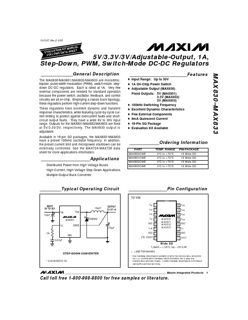
STEP-DOWN CONVER________________________________________________________________ Maxim Integrated Products
1
Call toll free 1-800-998-8800 for free samples or literature.
元器件交易网
5V/3.3V/3V/Adjustable-Output, 1A, Step-Down, PWM, Switch-Mode DC-DC Regulators MAX830–MAX833
ABSOLUTE MAXIMUM RATINGS
Input Voltage . . . . . . . . . . . . . . . . . . . . . . . . . . . . . . . . . . . . . . . . . . . . . . . . . . 40V Switch Voltage with Respect to Input Voltage. . . . . . . . . . . . . . . . 50V Switch Voltage with Respect to GND (VSW negative) (Note 1). . . . . . . . . . . . . . . . . . . . . . . . . . . . . . . . . . . . . 20V FB/SENSE Voltage . . . . . . . . . . . . . . . . . . . . . . . . . . . . . . . . . . . -0.3V, +10V SHUT Voltage (not to exceed VIN) . . . . . . . . . . . . . . . . . . . . . . . . . . . . 30V Note 1: Do not exceed switch-to-input voltage limitation.
MAX825中文资料
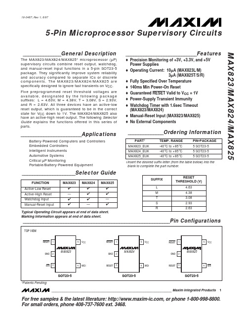
_______________General DescriptionThe MAX823/MAX824/MAX825* microprocessor (µP)supervisory circuits combine reset output, watchdog,and manual-reset input functions in a 5-pin SOT23-5package. They significantly improve system reliability and accuracy compared to separate ICs or discrete components. The MAX823/MAX824/MAX825 are specifically designed to ignore fast transients on V CC .Five preprogrammed reset threshold voltages are available, designated by the following package suffixes: L = 4.63V, M = 4.38V, T = 3.08V, S = 2.93V,and R = 2.63V. All three devices have an active-low reset output, which is guaranteed to be in the correct state for V CC down to 1V. The MAX824/MAX825 also have an active-high reset output. The following Selector Guide explains the functions offered in this series of parts.________________________ApplicationsBattery-Powered Computers and Controllers Embedded Controllers Intelligent Instruments Automotive Systems Critical µP MonitoringPortable/Battery-Powered Equipment____________________________Featureso Precision Monitoring of +3V, +3.3V, and +5V Power Supplies o Operating Current: 10µA (MAX823L/M)3µA (MAX825T/S/R)o Fully Specified Over Temperature o 140ms Min Power-On Reseto Guaranteed RESET Valid to V CC = 1V o Power-Supply Transient Immunity o Watchdog Timer with 1.6sec Timeout (MAX823/MAX824)o Manual-Reset Input (MAX823/MAX825)o No External ComponentsMAX823/MAX824/MAX8255-Pin Microprocessor Supervisory Circuits________________________________________________________________Maxim Integrated Products1__________________________________________________________Pin Configurations_____________________Selector Guide19-0487; Rev 1; 6/97______________Ordering Information†Insert the desired suffix letter (from the table below) into the blank to complete the part number.For free samples & the latest literature: , or phone 1-800-998-8800.For small orders, phone 408-737-7600 ext. 3468.Typical Operating Circuit appears at end of data sheet.Marking Information appears at end of data sheet.*Patents PendingM A X 823/M A X 824/M A X 8255-Pin Microprocessor Supervisory Circuits 2_______________________________________________________________________________________ABSOLUTE MAXIMUM RATINGSELECTRICAL CHARACTERISTICS(V CC = +4.75V to +5.5V for MAX82_L, V CC = +4.5V to +5.5V for MAX82_M, V CC = +3.15V to +3.6V for MAX82_T, V CC = +3V to +3.6V for MAX82_S, V CC = +2.7V to +3.6V for MAX82_R, T A = T MIN to T MAX , unless otherwise noted. Typical values are at T A = +25°C.) (Note 1)Stresses beyond those listed under “Absolute Maximum Ratings” may cause permanent damage to the device. These are stress ratings only, and functional operation of the device at these or any other conditions beyond those indicated in the operational sections of the specifications is not implied. Exposure to absolute maximum rating conditions for extended periods may affect device reliability.V CC ........................................................................-0.3V to +6.0V All Other Pins..............................................-0.3V to (V CC + 0.3V)Input Current, All Pins Except RESET and RESET ..............20mA Output Current, RESET, RESET ..........................................20mA Rate of Rise, V CC ............................................................100V/µs Continuous Power Dissipation (T A = +70°C)SOT23-5 (derate 7.1mW/°C above +70°C)...................571mWOperating Temperature RangeMAX82_EUK.....................................................-40°C to +85°C Storage Temperature Range.............................-65°C to +160°C Lead Temperature (soldering, 10sec).............................+300°CELECTRICAL CHARACTERISTICS (continued)(V CC= +4.75V to +5.5V for MAX82_L, V CC= +4.5V to +5.5V for MAX82_M, V CC= +3.15V to +3.6V for MAX82_T, V CC= +3V to +3.6V for MAX82_S, V CC= +2.7V to +3.6V for MAX82_R, T A= T MIN to T MAX, unless otherwise noted. Typical values are at T A= +25°C.) (Note 1)Note 1:Over-temperature limits are guaranteed by design and not production tested.Note 2:The RESET short-circuit current is the maximum pull-up current when RESET is driven low by a µP bidirectional reset pin. Note 3:WDI is internally serviced within the watchdog period if WDI is left unconnected.Note 4:The WDI input current is specified as the average input current when the WDI input is driven high or low. The WDI input is designed to drive a three-stated-output device with a 10µA maximum leakage current and a maximum capacitive load of200pF. This output device must be able to source and sink at least 200µA when active.MAX823/MAX824/MAX8255-Pin Microprocessor Supervisory Circuits _______________________________________________________________________________________3M A X 823/M A X 824/M A X 8255-Pin Microprocessor Supervisory Circuits 4_________________________________________________________________________________________________________________________________Typical Operating Characteristics(MAX823L, V CC = +5V, T A = +25°C, unless otherwise noted.)12.57.5-40-2040100V CC SUPPLY CURRENT vs. TEMPERATURE8.58.09.011.512.0M A X 823/4/5-01TEMPERATURE (°C)S U P P L Y C U R R E N T (µA )020806010.511.09.510.0250150-40-2040100RESET TIMEOUT PERIOD vs. TEMPERATURE170160180230240M A X 823/4/5-02TEMPERATURE (°C)R E S E T T I M E O U T P E R I O D (m s )020806021022019020030-40-2040100RESET COMPARATOR PROPAGATION DELAYvs. TEMPERATURE525TEMPERATURE (°C)P R O P A G A T I O N D E L A Y (µs )02080602010152.01.0-40-2040100WATCHDOG TIMEOUT PERIODvs. TEMPERATURE1.21.11.31.81.9M A X 823/4/5-04TEMPERATURE (°C)W A T C H D O G T I M E O U T P E R I O D (s e c )2080601.61.71.41.5 1.060.940.960.981.001.021.04-40-2040100NORMALIZED RESET THRESHOLD VOLTAGE vs. TEMPERATUREM A X 823/4/5-05TEMPERATURE (°C)N O R M A L I Z E D R E S E T T H R E S H O L D (V )020806002040 60 80 10012014016040100200180120140160MAXIMUM V CC TRANSIENT DURATION vs. RESET THRESHOLD OVERDRIVERESET THRESHOLD OVERDRIVE (mV), V RST - V CCT R A N S I E N T D U R A T I O N (µs )208060MAX823/MAX824/MAX8255-Pin Microprocessor Supervisory Circuits_______________________________________________________________________________________5______________________________________________________________Pin DescriptionFigure 1. Functional DiagramM A X 823/M A X 824/M A X 8255-Pin Microprocessor Supervisory Circuits 6______________________________________________________________________________________________________Detailed DescriptionRESET OutputA microprocessor’s (µP’s) reset input starts the µP in a known state. The MAX823/MAX824/MAX825 µP super-visory circuits assert a reset to prevent code-execution errors during power-up, power-down, and brownout conditions. RESET is guaranteed to be a logic low for V CC down to 1V. Once V CC exceeds the reset thresh-old, an internal timer keeps RESET low for the specified reset timeout period (t RP ); after this interval, RESET returns high (Figure 2).If a brownout condition occurs (V CC dips below the reset threshold), RESET goes low. Each time RESET is asserted it stays low for the reset timeout period. Any time V CC goes below the reset threshold the internal timer restarts. RESET both sources and sinks current.RESET on the MAX824/MAX825 is the inverse of RESET .Manual-Reset Input (MAX823/MAX825)Many µP-based products require manual-reset capabili-ty, allowing the operator, a test technician, or external logic circuitry to initiate a reset. On the MAX823/MAX825, a logic low on MR asserts reset. Reset remains asserted while MR is low, and for t RP (200ms nominal)after it returns high. MR has an internal 52k Ωpull-up resistor, so it can be left open if not used. This input can be driven with CMOS-logic levels or with open-drain/collector outputs. Connect a normally open momentary switch from MR to GND to create a manual-reset func-tion; external debounce circuitry is not required. If MR is driven from long cables or the device is used in a noisy environment, connect a 0.1µF capacitor from MR to GND to provide additional noise immunity.Watchdog Input (MAX823/MAX824)In the MAX823/MAX824, the watchdog circuit monitors the µP’s activity. If the µP does not toggle the watchdog input (WDI) within t WD (1.6sec), reset asserts. The inter-nal 1.6sec timer is cleared by either a reset pulse or by toggling WDI, which detects pulses as short as 50ns.While reset is asserted, the timer remains cleared and does not count. As soon as reset is released, the timer starts counting (Figure 3).Disable the watchdog function by leaving WDI uncon-nected or by three-stating the driver connected to WDI.The watchdog input is internally driven low during the first 7/8 of the watchdog timeout period and high for the last 1/8 of the watchdog timeout period. When WDI is left unconnected, this internal driver clears the 1.6sec timer every 1.4sec. When WDI is three-stated or uncon-nected, the maximum allowable leakage current is 10µA and the maximum allowable load capacitance is 200pF.__________Applications InformationWatchdog Input CurrentThe MAX823/MAX824 WDI inputs are internally driven through a buffer and series resistor from the watchdog counter (Figure 1). When WDI is left unconnected, the watchdog timer is serviced within the watchdog timeout period by a low-high-low pulse from the counter chain.For minimum watchdog input current (minimum overall power consumption), leave WDI low for the majority of the watchdog timeout period, pulsing it low-high-low once within the first 7/8 of the watchdog timeout period to reset the watchdog timer. If WDI is externally driven high for the majority of the timeout period, up to 160µA can flow into WDI.Figure 2. Reset Timing Diagram Figure 3. MAX823/MAX824 Watchdog Timing RelationshipInterfacing to µPs with Bidirectional Reset PinsThe RESET output maximum pull-up current is 800µA for L/M versions (400µA for T/S/R versions). This allows µPs with bidirectional resets, such as the 68HC11, to force RESET low when the MAX823/MAX824/MAX825are pulling RESET high (Figure 4).Negative-Going V CC TransientsThese supervisors are relatively immune to short-duration, negative-going V CC transients (glitches), which usually do not require the entire system to shut down.Resets are issued to the µP during power-up, power-down, and brownout conditions.The Typical Operating Characteristics show a graph of the MAX823L’s Maximum V CC Transient Duration vs.Reset Threshold Overdrive, for which reset pulses are not generated. The graph was produced using nega-tive-going V CC pulses, starting at 5V and ending below the reset threshold by the magnitude indicated (reset threshold overdrive). The graph shows the maximum pulse width that a negative-going V CC transient can typically have without triggering a reset pulse. As the amplitude of the transient increases (i.e., goes farther below the reset threshold), the maximum allowable pulse width decreases. Typically, a V CC transient that goes 100mV below the reset threshold and lasts for 15µs or less will not trigger a reset pulse.An optional 0.1µF bypass capacitor mounted close to V CC provides additional transient immunity.Watchdog Software Considerations(MAX823/MAX824)One way to help the watchdog timer monitor software execution more closely is to set and reset the watchdog input at different points in the program, rather than pulsing the watchdog input high-low-high or low-high-low. This technique avoids a stuck loop, in which the watchdog timer would continue to be reset inside the loop, keeping the watchdog from timing out.Figure 5 shows an example of a flow diagram where the I/O driving the watchdog input is set high at the begin-ning of the program, set low at the beginning of every subroutine or loop, then set high again when the pro-gram returns to the beginning. If the program should hang in any subroutine, the problem would quickly be corrected, since the I/O is continually set low and the watchdog timer is allowed to time out, causing a reset or interrupt to be issued. As described in the Watchdog Input Current section, this scheme results in higher time average WDI input current than does leaving WDI low for the majority of the timeout period and periodically pulsing it low-high-low.MAX823/MAX824/MAX8255-Pin Microprocessor Supervisory Circuits_______________________________________________________________________________________7Figure 4. Interfacing to µPs with Bidirectional Resets Figure 5. Watchdog Flow DiagramM A X 823/M A X 824/M A X 8255-Pin Microprocessor Supervisory Circuits Maxim cannot assume responsibility for use of any circuitry other than circuitry entirely embodied in a Maxim product. No circuit patent licenses are implied. Maxim reserves the right to change the circuitry and specifications without notice at any time.8____________________Maxim Integrated Products, 120 San Gabriel Drive, Sunnyvale, CA 94086 408-377-7600©1997 Maxim Integrated ProductsPrinted USAis a registered trademark of Maxim Integrated Products.__________Typical Operating Circuit___________________Chip Information______________Package InformationTRANSISTOR COUNT: 607。
MAX232中文资料.pdf
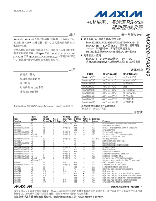
________________________________MAX220–MAX249 / Lj EIA/TIA-232E V.28/V.24 Lj ±12V ăӼ Lj 5μW ăMAX225ĂMAX233ĂMAX235 MAX245/MAX246/MAX247ԥ ԩ Lj ғ ă________________________________ӯRS-232 RS-232_______________________♦ Ă ESD үMAX3222E/MAX3232E/MAX3237E/MAX3241E/MAX3246E ǖ+3.0V +5.5V Ă Ă 1Mbps Ă 0.1μFRS-232 (MAX3246E UCSP TM )♦ ӊMAX221E ǖ±15kV ESD ү Ă+5V Ă1μA ĂAutoShutdown TM RS-232MAX220–MAX249+5V Ă RS-232/_____________________________________________________________________ ӹ19-4323; Rev 15; 1/06_____________________________ࢾ৪ቧᇦ)ኚ*Ᏼၫᓾ೯ࡼᔢઁ߲ă*ൡຢਖৃLj༿ᎧޣೊᇹăAutoShutdown UCSP Maxim Integrated Products, Inc. Ӷă۾ᆪဵNbyjnᑵါ፞ᆪᓾ೯ࡼፉᆪLjNbyjnݙ࣪डፉᒦࡀᏴࡼތፊᎅࠥޘညࡼࡇᇙঌᐊă༿ᓖፀፉᆪᒦభถࡀᏴᆪᔊᔝᒅडፉࡇᇙLjྙኊཀྵཱྀྀੜࠤᎫࡼᓰཀྵቶLj༿ݬఠNbyjnᄋࡼ፞ᆪۈᓾ೯ăჃནॅዹອਜ਼ᔢቤۈࡼၫᓾ೯Lj༿षᆰNbyjnࡼᓍǖxxx/nbyjn.jd/dpn/doăM A X 220–M A X 249+5V Ă RS-232 / 2_______________________________________________________________________________________ABSOLUTE MAXIMUM RATINGS—MAX220/222/232A/233A/242/243ELECTRICAL CHARACTERISTICS—MAX220/222/232A/233A/242/243(V CC = +5V ±10%, C1–C4 = 0.1μF‚ MAX220, C1 = 0.047μF, C2–C4 = 0.33μF, T A = T MIN to T MAX ‚ unless otherwise noted.)Note 1:For the MAX220, V+ and V- can have a maximum magnitude of 7V, but their absolute difference cannot exceed 13V.Note 2:Input voltage measured with T OUT in high-impedance state, SHDN or V CC = 0V.Note 3:Maximum reflow temperature for the MAX233A is +225°C.Stresses beyond those listed under “Absolute Maximum Ratings” may cause permanent damage to the device. These are stress ratings only, and functional operation of the device at these or any other conditions beyond those indicated in the operational sections of the specifications is not implied. Exposure to absolute maximum rating conditions for extended periods may affect device reliability.Supply Voltage (V CC )...............................................-0.3V to +6V V+ (Note 1)..................................................(V CC - 0.3V) to +14V V- (Note 1).............................................................+0.3V to +14V Input VoltagesT IN ..............................................................-0.3V to (V CC - 0.3V)R IN (Except MAX220)........................................................±30V R IN (MAX220).....................................................................±25V T OUT (Except MAX220) (Note 2).......................................±15V T OUT (MAX220)...............................................................±13.2V Output VoltagesT OUT ...................................................................................±15V R OUT .........................................................-0.3V to (V CC + 0.3V)Driver/Receiver Output Short Circuited to GND.........Continuous Continuous Power Dissipation (T A = +70°C)16-Pin Plastic DIP (derate 10.53mW/°C above +70°C).842mW18-Pin Plastic DIP (derate 11.11mW/°C above +70°C)..889mW 20-Pin Plastic DIP (derate 8.00mW/°C above +70°C)..440mW 16-Pin Narrow SO (derate 8.70mW/°C above +70°C)...696mW 16-Pin Wide SO (derate 9.52mW/°C above +70°C)......762mW 18-Pin Wide SO (derate 9.52mW/°C above +70°C)......762mW 20-Pin Wide SO (derate 10.00mW/°C above +70°C)....800mW 20-Pin SSOP (derate 8.00mW/°C above +70°C)..........640mW 16-Pin CERDIP (derate 10.00mW/°C above +70°C).....800mW 18-Pin CERDIP (derate 10.53mW/°C above +70°C).....842mW Operating Temperature RangesMAX2_ _AC_ _, MAX2_ _C_ _.............................0°C to +70°C MAX2_ _AE_ _, MAX2_ _E_ _..........................-40°C to +85°C MAX2_ _AM_ _, MAX2_ _M_ _.......................-55°C to +125°C Storage Temperature Range.............................-65°C to +160°C Lead Temperature (soldering, 10s) (Note 3)...................+300°CMAX220–MAX249+5V Ă RS-232/_______________________________________________________________________________________3OUT IN ELECTRICAL CHARACTERISTICS—MAX220/222/232A/233A/242/243 (continued)(V CC = +5V ±10%, C1–C4 = 0.1μF‚ MAX220, C1 = 0.047μF, C2–C4 = 0.33μF, T A = T MIN to T MAX ‚ unless otherwise noted.)M A X 220–M A X 249+5V Ă RS-232 / 4_______________________________________________________________________________________________________________________________________________________MAX220/MAX222/MAX232A/MAX233A/MAX242/MAX243108-1051525OUTPUT VOLTAGE vs. LOAD CURRENT-4-6-8-2642LOAD CURRENT (mA)O U T P U T V O L T A G E (V )1002011104104060AVAILABLE OUTPUT CURRENTvs. DATA RATE65798DATA RATE (kb/s)O U T P U T C U R R E N T (m A )203050+10V-10VMAX222/MAX242ON-TIME EXITING SHUTDOWN+5V +5V 0V0V 500μs/div V +, V - V O L T A G E (V )ELECTRICAL CHARACTERISTICS—MAX220/222/232A/233A/242/243 (continued)(V CC = +5V ±10%, C1–C4 = 0.1μF‚ MAX220, C1 = 0.047μF, C2–C4 = 0.33μF, T A = T MIN to T MAX ‚ unless otherwise noted.)MAX220–MAX249+5V Ă RS-232/_______________________________________________________________________________________5V CC ...........................................................................-0.3V to +6V V+................................................................(V CC - 0.3V) to +14V V-............................................................................+0.3V to -14V Input VoltagesT IN ............................................................-0.3V to (V CC + 0.3V)R IN ......................................................................................±30V Output VoltagesT OUT ...................................................(V+ + 0.3V) to (V- - 0.3V)R OUT .........................................................-0.3V to (V CC + 0.3V)Short-Circuit Duration, T OUT ......................................Continuous Continuous Power Dissipation (T A = +70°C)14-Pin Plastic DIP (derate 10.00mW/°C above +70°C)....800mW 16-Pin Plastic DIP (derate 10.53mW/°C above +70°C)....842mW 20-Pin Plastic DIP (derate 11.11mW/°C above +70°C)....889mW 24-Pin Narrow Plastic DIP(derate 13.33mW/°C above +70°C)..........1.07W24-Pin Plastic DIP (derate 9.09mW/°C above +70°C)......500mW 16-Pin Wide SO (derate 9.52mW/°C above +70°C).........762mW20-Pin Wide SO (derate 10.00mW/°C above +70°C).......800mW 24-Pin Wide SO (derate 11.76mW/°C above +70°C).......941mW 28-Pin Wide SO (derate 12.50mW/°C above +70°C) .............1W 44-Pin Plastic FP (derate 11.11mW/°C above +70°C).....889mW 14-Pin CERDIP (derate 9.09mW/°C above +70°C)..........727mW 16-Pin CERDIP (derate 10.00mW/°C above +70°C)........800mW 20-Pin CERDIP (derate 11.11mW/°C above +70°C)........889mW 24-Pin Narrow CERDIP(derate 12.50mW/°C above +70°C)..............1W24-Pin Sidebraze (derate 20.0mW/°C above +70°C)..........1.6W 28-Pin SSOP (derate 9.52mW/°C above +70°C).............762mW Operating Temperature RangesMAX2 _ _ C _ _......................................................0°C to +70°C MAX2 _ _ E _ _...................................................-40°C to +85°C MAX2 _ _ M _ _................................................-55°C to +125°C Storage Temperature Range.............................-65°C to +160°C Lead Temperature (soldering, 10s) (Note 4)...................+300°CABSOLUTE MAXIMUM RATINGS—MAX223/MAX230–MAX241ELECTRICAL CHARACTERISTICS—MAX223/MAX230–MAX241(MAX223/230/232/234/236/237/238/240/241, V CC = +5V ±10%; MAX233/MAX235, V CC = 5V ±5%‚ C1–C4 = 1.0μF; MAX231/MAX239,V CC = 5V ±10%; V+ = 7.5V to 13.2V; T A = T MIN to T MAX ; unless otherwise noted.)Stresses beyond those listed under “Absolute Maximum Ratings” may cause permanent damage to the device. These are stress ratings only, and functional operation of the device at these or any other conditions beyond those indicated in the operational sections of the specifications is not implied. Exposure to absolute maximum rating conditions for extended periods may affect device reliability.Note 4:Maximum reflow temperature for the MAX233/MAX235 is +225°C.M A X 220–M A X 249+5V Ă RS-232 / 6_______________________________________________________________________________________ELECTRICAL CHARACTERISTICS—MAX223/MAX230–MAX241 (continued)(MAX223/230/232/234/236/237/238/240/241, V CC = +5V ±10%; MAX233/MAX235, V CC = 5V ±5%‚ C1–C4 = 1.0μF; MAX231/MAX239,V CC = 5V ±10%; V+ = 7.5V to 13.2V; T A = T MIN to T MAX ; unless otherwise noted.)MAX220–MAX249+5V Ă RS-232/_______________________________________________________________________________________7_______________________________________________________________MAX223/MAX230–MAX2418.56.54.55.5TRANSMITTER OUTPUT VOLTAGE (V OH ) vs. V CC7.08.0V CC (V)V O H (V )5.07.57.46.02500TRANSMITTER OUTPUT VOLTAGE (V OH )vs. LOAD CAPACITANCE AT DIFFERENT DATA RATES6.46.27.27.0LOAD CAPACITANCE (pF)V O H (V )1500100050020006.86.612.04.02500TRANSMITTER SLEW RATE vs. LOAD CAPACITANCE6.05.011.09.010.0LOAD CAPACITANCE (pF)S L E W R A T E (V /μs )1500100050020008.07.0-6.0-9.04.55.5TRANSMITTER OUTPUT VOLTAGE (V OL ) vs. V CC-8.0-8.5-6.5-7.0V CC (V)V O L (V )5.0-7.5-6.0-7.62500TRANSMITTER OUTPUT VOLTAGE (V OL )vs. LOAD CAPACITANCE AT DIFFERENT DATA RATES-7.0-7.2-7.4-6.2-6.4LOAD CAPACITANCE (pF)V O L (V )150010005002000-6.6-6.810-105101520253035404550TRANSMITTER OUTPUT VOLTAGE (V+, V-)vs. LOAD CURRENT-2-6-4-886CURRENT (mA)V +, V - (V )420*SHUTDOWN POLARITY IS REVERSED FOR NON MAX241 PARTSV+, V- WHEN EXITING SHUTDOWN(1μF CAPACITORS)MAX220-13SHDN*V-O V+500ms/divM A X 220–M A X 249+5V Ă RS-232 / 8_______________________________________________________________________________________ABSOLUTE MAXIMUM RATINGS—MAX225/MAX244–MAX249ELECTRICAL CHARACTERISTICS—MAX225/MAX244–MAX249(MAX225, V CC = 5.0V ±5%; MAX244–MAX249, V CC = +5.0V ±10%, external capacitors C1–C4 = 1μF; T A = T MIN to T MAX ; unless oth-erwise noted.)Stresses beyond those listed under “Absolute Maximum Ratings” may cause permanent damage to the device. These are stress ratings only, and functional operation of the device at these or any other conditions beyond those indicated in the operational sections of the specifications is not implied. Exposure to absolute maximum rating conditions for extended periods may affect device reliability.Supply Voltage (V CC )...............................................-0.3V to +6V Input VoltagesT IN ‚ ENA , ENB , ENR , ENT , ENRA ,ENRB , ENTA , ENTB ..................................-0.3V to (V CC + 0.3V)R IN .....................................................................................±25V T OUT (Note 5).....................................................................±15V R OUT ........................................................-0.3V to (V CC + 0.3V)Short Circuit (one output at a time)T OUT to GND............................................................Continuous R OUT to GND............................................................ContinuousContinuous Power Dissipation (T A = +70°C)28-Pin Wide SO (derate 12.50mW/°C above +70°C).............1W 40-Pin Plastic DIP (derate 11.11mW/°C above +70°C)...611mW 44-Pin PLCC (derate 13.33mW/°C above +70°C)...........1.07W Operating Temperature RangesMAX225C_ _, MAX24_C_ _ ..................................0°C to +70°C MAX225E_ _, MAX24_E_ _ ...............................-40°C to +85°C Storage Temperature Range.............................-65°C to +160°C Lead Temperature (soldering,10s) (Note 6)....................+300°CNote 5:Input voltage measured with transmitter output in a high-impedance state, shutdown, or V CC = 0V.Note 6:Maximum reflow temperature for the MAX225/MAX245/MAX246/MAX247 is +225°C.MAX220–MAX249+5V Ă RS-232/_______________________________________________________________________________________9Note 7:The 300Ωminimum specification complies with EIA/TIA-232E, but the actual resistance when in shutdown mode or V CC =0V is 10M Ωas is implied by the leakage specification.ELECTRICAL CHARACTERISTICS—MAX225/MAX244–MAX249 (continued)(MAX225, V CC = 5.0V ±5%; MAX244–MAX249, V CC = +5.0V ±10%, external capacitors C1–C4 = 1μF; T A = T MIN to T MAX ; unless oth-erwise noted.)M A X 220–M A X 249+5V Ă RS-232 / 10_____________________________________________________________________________________________________________________________________________________MAX225/MAX244–MAX24918212345TRANSMITTER SLEW RATE vs. LOAD CAPACITANCE86416LOAD CAPACITANCE (nF)T R A N S M I T T E R S L E W R A T E (V /μs )14121010-105101520253035OUTPUT VOLTAGEvs. LOAD CURRENT FOR V+ AND V--2-4-6-88LOAD CURRENT (mA)O U T P U T V O L T A G E (V )64209.05.012345TRANSMITTER OUTPUT VOLTAGE (V+, V-)vs. LOAD CAPACITANCE AT DIFFERENT DATA RATES6.05.58.5LOAD CAPACITANCE (nF)V +, V (V )8.07.57.06.5MAX220–MAX249+5V RS-232/1. 2.3. 4.M A X 220–M A X 249+5V RS-232 / ENT ENR OPERATION STATUS TRANSMITTERSRECEIVERS00Normal Operation All Active All Active 01Normal Operation All Active All 3-State10Shutdown All 3-State All Low-Power Receive Mode 11ShutdownAll 3-StateAll 3-Stateӹ1a. MAX245ENT ENR OPERATION STATUS TRANSMITTERS RECEIVERSTA1–TA4TB1–TB4RA1–RA5RB1–RB500Normal Operation All Active All Active All Active All Active 01Normal Operation All Active All Active RA1–RA4 3-State,RA5 Active RB1–RB4 3-State,RB5 Active 1ShutdownAll 3-StateAll 3-StateAll Low-Power Receive Mode All Low-Power Receive Mode 11Shutdown All 3-State All 3-StateRA1–RA4 3-State,RA5 Low-Power Receive ModeRB1–RB4 3-State,RB5 Low-Power Receive Modeӹ1b. MAX245ӹ1c. MAX246ENA ENB OPERATION STATUS TRANSMITTERS RECEIVERSTA1–TA4TB1–TB4RA1–RA5RB1–RB500Normal Operation All Active All Active All Active All Active 01Normal Operation All Active All 3-State All Active RB1–RB4 3-State,RB5 Active 1ShutdownAll 3-StateAll ActiveRA1–RA4 3-State,RA5 Active All Active 11Shutdown All 3-State All 3-StateRA1–RA4 3-State,RA5 Low-Power Receive ModeRB1–RB4 3-State,RA5 Low-Power Receive ModeMAX220–MAX249+5V RS-232/M A X 220–M A X 249____________________________MAX220–MAX249Ҫ 4 ԩ ǖ ӏDC-DC ĂRS-232 ĂRS-232 Lj ăӏMAX220–MAX249 ԩ ӏLj +5V ±10V ( )Lj RS-232 ă C1 +5V ӂLj V+ C3 +10V Ǘ C2 +10V V- C4 -10V ă+10V (V+) -10V (V-) Lj ԩ (Ը ԩ )Ǘ MAX225 MAX245–MAX247 Lj ԥ ăV+ V- Lj ă V+ĂV- ԩ Lj ԥ V+ĂV- EIA/TIA-232E ±5V ăMAX222ĂMAX225ĂMAX230ĂMAX235ĂMAX236ĂMAX240ĂMAX241 MAX245–MAX249 Lj Ө V+ V- ԩ ă LjV- 0V LjV+ +5V ă +10V ԩ V+ ( ԥ ԩ ӏ դ +10V) Lj ԥ Ѡ C1LjԌ Ӥ SHDN V CC Lj V+Ӈ ԩ V CC ăRS-232Ӷ 5kΩ RS-232 LjԌ V CC =+5V Lj ҈ ±8V ă ҈ ү EIA/TIA-232E V.28 Lj ±5V Lj Ҫ 3kΩ ĂV CC = +4.5V ă (V +-1.3V) (V- +0.5V)ăTTL CMOS ă ԥ Lj Ă V CC 400kΩ (MAX220 )ă Lj ă Ӈ Lj ԩ ի 12μA ă Ă ӇLj ӡLjԌ Lj ի Ѡ( 25μA)ă Ӈ ±15V ă Lj ի 8μA ăMAX220ԥ ӄ ԩ Lj ԥ Lj GND V CC ăMAX239 Lj MAX223ĂMAX225ĂMAX235ĂMAX236ĂMAX240 MAX241 ӄ ăӹ2 ă( MAX225/MAX235/MAX236/MAX239–MAX241)Lj TTL/CMOS Ă Ǘ Lj Lj ăLj Ӈ ӡLj 1μA Lj Ӈ ă 1μA Lj ӯ Ӈ 0V (V CC +6V)ă -0.5V Lj Lj 1kΩ ă Ӈ V CC +6V Lj 1kΩ ă҈ 30V/μs Lj EIA/TIA-232E V.28 ă҈ ǖ 24V/μs Lj3Ω 2500pF 10V/μs ăRS-232EIA/TIA-232E V.28 3V 0Lj Lj ă 0.8V 2.4V Lj TTL Lj EIA/TIA-232E V.28 ă±25V LjԌ Ӷ 5kΩ ă V.28 EIA/TIA-232E ă+5V RS-232 /ӹMAX220–MAX249+5V RS-232/0.5V LjԌ ү0.2V ă Lj Ӱ դ ӰLj ă 600ns Lj ҈ ăMAX223ĂMAX242 MAX245–MAX249 Lj IC Lj ă ի ă Lj Lj ӄ Ă ă Ճ ă—MAX243MAX243 MAX232A Lj Ӽ RS-232 ү ă CTS RTS Ӈ Lj ԥ ăԥӤ ԥ ԥ ӄăү -0.8V Lj ԥ +1.4V ă Lj ԯӰ ă Lj 0Lj Đ đ ă իLjMAX243 (+1.4V ) (TD RD)Lj (DTR ĂDTS ĂCTS ĂRTS ) ăRS-232 դ Ѣ EIA/TIA-232E LjԳ ү ă Ӈ Ă Lj Ӱ ă IC ă Ө Lj Ӥ Ӈ Lj ă—MAX222–MAX242LjMAX222ĂMAX235ĂMAX236ĂMAX240 MAX241 Ӈ ă LjMAX223 MAX242 ү ă Lj ӰLj 2.5μs ă Lj CMOS ăMAX223 MAX242 ( MAX242 EN ĂMAX223 EN)Lj SHDN ( MAX241 SHDN) ă SHDN ( MAX241 SHDN ) ăMAX225 5 5 ǗMAX245 10 8 ă ă ENT Lj ӏ ӡԌ ă Lj 25μA Lj ү Lj ( )ăMAX225 5 ENR ăMAX245 8 ENR Lj (RA5 RB5) ү ă ENR LjRA1–RA4 RB1–RB4 ăMAX225 MAX245–MAX249 ăǖ ( ի )Ă ( ) ( ү )ă ă ǖ ( ի ) ( )ă Ӈ ă Ӈ Lj ă Lj ăM A X 220–M A X 249ӹ1a–1d ăMAX244 Lj Ҫ ӹ ăMAX246 10 8 Lj Lj Ӽ ՊăA Պ (ENA ) Lj 4 A Պ Ǘ LjB Պ (ENB ) 4 B Պ ă MAX245 Lj A Պ B Պ (RA5 RB5) ү ă A ՊĂB Պ Ӈ (ENA =ENB =+5V) Lj ăMAX247 9 8 Lj 4 ăENRA ĂENRB Lj Ӽ 4 ăENTA ĂENTB Lj Ӽ 4 ă 9 (RB5) ă ENTA ENTB ăMAX248 8 8 Lj 4 ăENRA ĂENRB Lj Ӽ 4ăENTA ĂENTB Lj Ӽ 4 ă ă ENTA ĂENTB Lj ăMAX249 10 6 Lj 4 ăENRA ĂENRB Lj Ӽ 5 ăENTA ĂENTB Lj Ӽ 3 ă ă ENTA ĂENTB Lj ă Ljү Lj 20kb/s ă____________________________5 25 ă LjV CC C1ĂC2 Lj ҈ ă+5V RS-232 /MAX220–MAX249+5V RS-232/5. MAX220/MAX232/MAX232A6. MAX222/MAX242M A X 220–M A X 249+5V RS-232 /7. MAX225MAX220–MAX249+5V RS-232/8. MAX223/MAX241M A X 220–M A X 249+5V RS-232 /9. MAX23010. MAX231MAX220–MAX249+5V RS-232/12. MAX23411. MAX233/MAX233AM A X 220–M A X 249+5V RS-232 /13. MAX235MAX220–MAX249+5V RS-232/14. MAX236M A X 220–M A X 249+5V RS-232 /15. MAX237MAX220–MAX249+5V RS-232/16. MAX238M A X 220–M A X 249+5V RS-232 /17. MAX239MAX220–MAX249+5V RS-232/18. MAX240M A X 220–M A X 249+5V RS-232 /19. MAX243MAX220–MAX249+5V RS-232/20. MAX244M A X 220–M A X 249+5V RS-232 /21. MAX245MAX220–MAX249+5V RS-232/______________________________________________________________________________________3122. MAX246M A X 220–M A X 249+5V RS-232 / 32______________________________________________________________________________________23. MAX247MAX220–MAX249+5V RS-232/______________________________________________________________________________________3324. MAX248M A X 220–M A X 249+5V RS-232 / 34______________________________________________________________________________________25. MAX249MAX220–MAX249+5V RS-232/______________________________________________________________________________________35_____________________________________________________________________ ( )*ൡຢਖৃLj༿ᎧޣೊᇹăM A X 220–M A X 249+5V RS-232 / _____________________________________________________________________ ( )*ൡຢਖৃLj༿Ꭷޣೊᇹă____________________________Lj Փ /packages ă_____________________________Rev 15 ǖ2–5Ă8Ă9Ă36ăNbyjnݙ࣪Nbyjnޘອጲᅪࡼྀੜ࢟വဧঌᐊLjጐݙᄋᓜಽభăNbyjnۣഔᏴྀੜဟମĂᎌྀੜᄰۨࡼ༄ᄋሆኀখޘອᓾ೯ਜ਼ਖৃࡼཚಽă36____________________Maxim Integrated Products, 120 San Gabriel Drive, Sunnyvale, CA 94086 408-737-7600©2006 Maxim Integrated ProductsNbyjn ဵNbyjn!Joufhsbufe!Qspevdut-!Jod/ࡼᓖݿܪăNbyjn ۱யێူࠀ۱ய9439ቧረᎆᑶܠ൩211194ॅ࢟જǖ911!921!1421࢟જǖ121.732262::ࠅᑞǖ121.732263::。
max2器件中文手册

max232中文资料及其应用
max232中文资料及其应用MAX232芯片是美信(MAXIM)公司专为RS-232标准串口设计的单电源电平转换芯片,使用 5v单电源供电。
器件特别适合电池供电系统,这是由于其低功耗关断模式可以将功耗减小到5uW以内。
MAX225、MAX233、MAX235以及MAX245/MAX246/MAX247不需要外部元件,推荐用于印刷电路板面积有限的应用。
MAX220–MAX249系列线驱动器/接收器,专为EIA/TIA-232E 以及V.28/V.24通信接口设计,尤其是无法提供±12V电源的应用。
当用单片机和PC机通过串口进行通信,尽管单片机有串行通信的功能,但单片机提供的信号电平和RS232的标准不一样,因此要通过max232这种类似的芯片进行电平转换。
引脚介绍:第一部分是电荷泵电路。
由1、2、3、4、5、6脚和4只电容构成。
功能是产生12v和-12v两个电源,提供给RS-232串口电平的需要。
第二部分是数据转换通道。
由7、8、9、10、11、12、13、14脚构成两个数据通道。
其中13脚(R1IN)、12脚(R1OUT)、11脚(T1IN)、14脚(T1OUT)为第一数据通道。
8脚(R2IN)、9脚(R2OUT)、10脚(T2IN)、7脚(T2OUT)为第二数据通道。
TTL/CMOS数据从T1IN、T2IN输入转换成RS-232数据从T1OUT、T2OUT送到电脑DB9插头;DB9插头的RS-232数据从R1IN、R2IN输入转换成TTL/CMOS数据后从R1OUT、R2OUT输出。
第三部分是供电。
15脚GND、16脚VCC( 5v)。
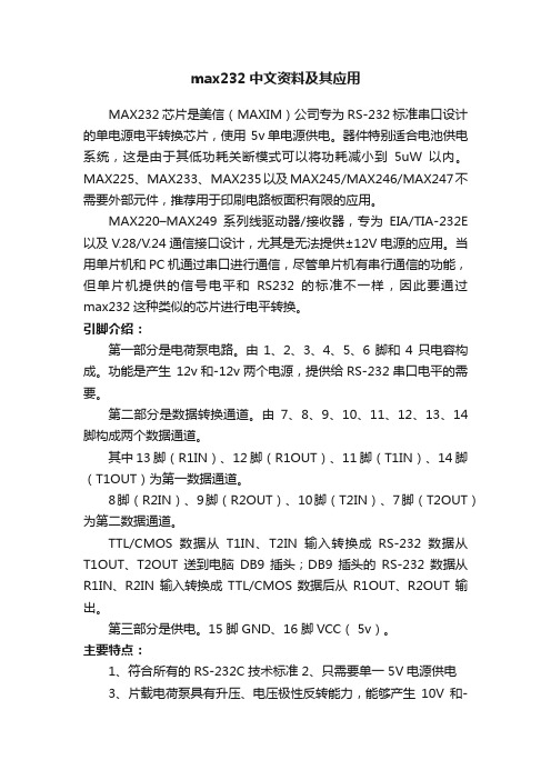
主要特点:1、符合所有的RS-232C技术标准2、只需要单一 5V电源供电3、片载电荷泵具有升压、电压极性反转能力,能够产生10V和-10V电压V 、V-4、功耗低,典型供电电流5mA5、内部集成2个RS-232C驱动器6、内部集成两个RS-232C接收器下图为MX232双串口的连接图,可以分别接单片机的串行通信口或者实验板的其它串行通信接口:max232应用电路,注意电容接法232是电荷泵芯片,可以完成两路TTL/RS-232电平的转换,它的的9、10、11、12引脚是TTL电平端,用来连接单片机的。
- 1、下载文档前请自行甄别文档内容的完整性,平台不提供额外的编辑、内容补充、找答案等附加服务。
- 2、"仅部分预览"的文档,不可在线预览部分如存在完整性等问题,可反馈申请退款(可完整预览的文档不适用该条件!)。
- 3、如文档侵犯您的权益,请联系客服反馈,我们会尽快为您处理(人工客服工作时间:9:00-18:30)。
General Description The MAX6381–MAX6390 microprocessor (µP) supervisory circuits monitor power-supply voltages from +1.8V to +5.0V while consuming only 3µA of supply current at +1.8V. Whenever V CC falls below the factory-set reset thresholds, the reset output asserts and remains assert-ed for a minimum reset timeout period after V CC rises above the reset threshold. Reset thresholds are available from +1.58V to +4.63V, in approximately 100mV incre-ments. Seven minimum reset timeout delays ranging from 1ms to 1200ms are available.The MAX6381/MAX6384/MAX6387 have a push-pull active-low reset output. The MAX6382/MAX6385/ MAX6388 have a push-pull active-high reset output, and the MAX6383/MAX6386/MAX6389/MAX6390 have an open-drain active-low reset output. The MAX6384/MAX6385/MAX6386 also feature a debounced manual reset input (with internal pullup resistor). The MAX6387/MAX6388/MAX6389 have an auxiliary input for monitoring a second voltage. The MAX6390 offers a manual reset input with a longer V CC reset timeout period (1120ms or 1200ms) and a shorter manual reset timeout (140ms or 150ms).The MAX6381/MAX6382/MAX6383 are available in 3-pin SC70 and6-pinµDFN packages and the MAX6384–MAX6390 are available in 4-pin SC70 andFeatures♦Factory-Set Reset Threshold Voltages Rangingfrom +1.58V to +4.63V in Approximately 100mVIncrements♦±2.5% Reset Threshold Accuracy OverTemperature (-40°C to +125°C)♦Seven Reset Timeout Periods Available: 1ms,20ms, 140ms, 280ms, 560ms, 1120ms,1200ms (min)♦3 Reset Output OptionsActive-Low Push-PullActive-High Push-PullActive-Low Open-Drain♦Reset Output State Guaranteed ValidDown to V CC= 1V♦Manual Reset Input (MAX6384/MAX6385/MAX6386)♦Auxiliary RESET IN(MAX6387/MAX6388/MAX6389)♦V CC Reset Timeout (1120ms or 1200ms)/ManualReset Timeout (140ms or 150ms) (MAX6390)♦Negative-Going V CC Transient Immunity♦Low Power Consumption of 6µA at +3.6Vand 3µA at +1.8V♦Pin Compatible withMAX809/MAX810/MAX803/MAX6326/MAX6327/MAX6328/MAX6346/MAX6347/MAX6348,and MAX6711/MAX6712/MAX6713♦Tiny 3-Pin/4-Pin SC70 and 6-Pin µDFN PackagesMAX6381–MAX6390 SC70/µDFN, Single/Dual Low-Voltage,Low-Power µP Reset Circuits ________________________________________________________________Maxim Integrated Products1Pin Configurations19-1839; Rev 4; 4/07Ordering InformationOrdering Information continued at end of data sheet.Typi cal Operati ng Ci rcui t appears at end of data sheet.Selector Guide appears at end of data sheet.after "XR", "XS", or "LT." Insert reset timeout delay (see ResetTimeout Delay table) after "D" to complete the part number.Sample stock is generally held on standard versions only (seeStandard Versions table). Standard versions have an orderincrement requirement of 2500 pieces. Nonstandard versionshave an order increment requirement of 10,000 pieces.Contact factory for availability of nonstandard versions.+Denotes a lead-free package.For pricing, delivery, and ordering information,please contact Maxim Direct at 1-888-629-4642,or visit Maxim’s website at .ComputersControllersIntelligent InstrumentsCritical µP and µCPower MonitoringPortable/Battery-Powered EquipmentDual Voltage SystemsM A X 6381–M A X 6390SC70/µDFN, Single/Dual Low-Voltage, Low-Power µP Reset CircuitsABSOLUTE MAXIMUM RATINGSELECTRICAL CHARACTERISTICS(V CC = full range, T A = -40°C to +125°C, unless otherwise specified. Typical values are at T A = +25°C.) (Note 1)Stresses beyond those listed under “Absolute Maximum Ratings” may cause permanent damage to the device. These are stress ratings only, and functional operation of the device at these or any other conditions beyond those indicated in the operational sections of the specifications is not implied. Exposure to absolute maximum rating conditions for extended periods may affect device reliability.V CC to GND..........................................................-0.3V to +6.0V RESET Open-Drain Output....................................-0.3V to +6.0V RESET , RESET (push-pull output)..............-0.3V to (V CC + 0.3V)MR , RESET IN.............................................-0.3V to (V CC + 0.3V)Input Current (V CC ).............................................................20mA Output Current (all pins).....................................................20mAContinuous Power Dissipation (T A = +70°C)3-Pin SC70 (derate 2.9mW/°C above +70°C)..............235mW 4-Pin SC70 (derate 3.1mW/°C above +70°C)..............245mW 6-Pin µDFN (derate 2.1mW/°C above +70°C)..........167.7mW Operating Temperature Range .........................-40°C to +125°C Storage Temperature Range.............................-65°C to +150°C Lead Temperature (soldering, 10s).................................+300°CMAX6381–MAX6390SC70/µDFN, Single/Dual Low-Voltage,Low-Power µP Reset Circuits_______________________________________________________________________________________3M A X 6381–M A X 6390SC70/µDFN, Single/Dual Low-Voltage, Low-Power µP Reset Circuits 4______________________________________________________________________________________Typical Operating Characteristics(T A = +25°C, unless otherwise noted.)215436789-40-105-25203550658095110125SUPPLY CURRENT vs. TEMPERATURE(NO LOAD)TEMPERATURE (°C)S U P P L Y C U R R E N T (µA )25292735333137394143-40-105-25203550658095110125POWER-DOWN RESET DELAYvs. TEMPERATURETEMPERATURE (°C)P O W E R -D O W N R E S E T D E L A Y (µs )0.940.980.961.021.001.061.041.08-40-10520-253550658095110125NORMALIZED POWER-UP RESET TIMEOUTvs. TEMPERATUREM A X 6381/90 t o c 03TEMPERATURE (°C)N O R M A L I Z E D R E S E T T I M E O U T P E R I O D0.9900.9851.0150.9950.9901.0001.0051.0101.020-40-10520-253550958011065125M A X 6381/90 t o c 04TEMPERATURE (°C)N O R M A L I Z E D R E S E T TH R E S H O L D NORMALIZED RESET THRESHOLDvs. TEMPERATURE00.40.20.80.61.01.2063912OUTPUT-VOLTAGE LOW vs. SINK CURRENTI SINK (mA)V O L (V )01.00.52.01.52.53.00500750250100012501500OUTPUT-VOLTAGE HIGH vs. SOURCE CURRENTI SOURCE (µA)V O H (V )45001100010010MAXIMUM TRANSIENT DURATION vs. RESET COMPARATOR OVERDRIVE15050350250500200100400300RESET COMPARATOR OVERDRIVE, V TH - V CC (mV)M A X I M U M T R A N S I E N T D U R A T I O N (µs )3.53.93.74.54.34.14.74.95.35.15.5-40-105-25203550658095110125RESET IN TO RESET DELAYvs. TEMPERATUREM A X 6381/90 t o c 08TEMPERATURE (°C)R E S E T I N D E L A Y (µs )MAX6381–MAX6390SC70/µDFN, Single/Dual Low-Voltage,Low-Power µP Reset CircuitsPin DescriptionM A X 6381–M A X 6390SC70/µDFN, Single/Dual Low-Voltage, Low-Power µP Reset Circuits 6_______________________________________________________________________________________Detailed DescriptionRESET OutputA µP reset input starts the µP in a known state. These µP supervisory circuits assert reset to prevent code execution errors during power-up, power-down, or brownout conditions.Reset asserts when V CC is below the reset threshold;once V CC exceeds the reset threshold, an internal timer keeps the reset output asserted for the reset timeout period. After this interval, reset output deasserts. Reset output is guaranteed to be in the correct logic state for V CC ≥1V.Manual Reset Input (MAX6384/MAX6385/MAX6386/MAX6390)Many µP-based products require manual reset capabil-ity, allowing the operator, a test technician, or external logic circuitry to initiate a reset. A logic low on MR asserts reset. Reset remains asserted while MR is low,and for the reset active timeout period (t RP ) after MR returns high. This input has an internal 63k Ωpullup resistor (1.56k Ωfor MAX6390), so it can be left uncon-nected if it is not used. MR can be driven with TTL or CMOS logic levels, or with open-drain/collector outputs.Connect a normally open momentary switch from MR to G ND to create a manual-reset function; external debounce circuitry is not required. If MR is driven from long cables or if the device is used in a noisy environ-ment, connecting a 0.1µF capacitor from MR to G ND provides additional noise immunity.RESET IN Comparator(MAX6387/MAX6388/MAX6389)RESET IN is compared to an internal +1.27V reference.If the voltage at RESET IN is less than 1.27V, reset asserts. Use the RESET IN comparator as a user-adjustable reset detector or as a secondary power-sup-ply monitor by implementing a resistor-divider at RESET IN (shown in Figure 1). Reset asserts when either V CC or RESET IN falls below its respective threshold volt-age. Use the following equation to set the threshold:V INTH = V THRST (R1/R2 + 1)where V THRST = +1.27V. To simplify the resistor selec-tion, choose a value of R2 and calculate R1:R1 = R2 [(V INTH /V THRST ) - 1]Since the input current at RESET IN is 50nA (max),large values can be used for R2 with no significant loss in accuracy.___________Applications InformationNegative-Going V CC TransientsIn addition to issuing a reset to the µP during power-up,power-down, and brownout conditions, the MAX6381–MAX6390 are relatively immune to short dura-tion negative-going V CC transients (glitches).The Typical Operating Characteristics section shows the Maximum Transient Durations vs. Reset Comparator Overdrive, for which the MAX6381–MAX6390 do not generate a reset pulse. This graph was generated usinga negative-going pulse applied to V CC , starting above the actual reset threshold and ending below it by the magnitude indicated (reset comparator overdrive). The graph indicates the typical maximum pulse width a neg-ative-going V CC transient may have without causing a reset pulse to be issued. As the magnitude of the tran-sient increases (goes farther below the reset threshold),the maximum allowable pulse width decreases. A 0.1µF capacitor mounted as close as possible to V CC provides additional transient immunity.Ensuring a Valid RESET Output Down to V CC = 0VThe MAX6381–MAX6390 are guaranteed to operate properly down to V CC = 1V. In applications that require valid reset levels down to V CC = 0V, a pulldown resistor to active-low outputs (push/pull only, Figure 2) and a pullup resistor to active-high outputs (push/pull only)will ensure that the reset line is valid while the reset out-put can no longer sink or source current. This schemedoes not work with the open-drain outputs of the MAX6383/MAX6386/MAX6389/MAX6390. The resistor value used is not critical, but it must be small enough not to load the reset output when V CC is above the reset threshold. For most applications, 100k Ωis ade-quate.MAX6381–MAX6390SC70/µDFN, Single/Dual Low-Voltage,Low-Power µP Reset Circuits_______________________________________________________________________________________7M A X 6381–M A X 6390SC70/µDFN, Single/Dual Low-Voltage, Low-Power µP Reset Circuits 8_______________________________________________________________________________________Selector GuideOrdering Information (continued)Note:Insert reset threshold suffix (see Reset Threshold table)after "XR", "XS", or "LT." Insert reset timeout delay (see Reset Timeout Delay table) after "D" to complete the part number.Sample stock is generally held on standard versions only (see Standard Versions table). Standard versions have an order increment requirement of 2500 pieces. Nonstandard versions have an order increment requirement of 10,000 pieces.Contact factory for availability of nonstandard versions.*MAX6390 is available with D4 or D7 timing only.+Denotes a lead-free package.MAX6381–MAX6390SC70/µDFN, Single/Dual Low-Voltage,Low-Power µP Reset Circuits_______________________________________________________________________________________9Chip InformationTRANSISTOR COUNT: 647PROCESS: BiCMOSPin Configurations (continued)M A X 6381–M A X 6390SC70/µDFN, Single/Dual Low-Voltage, Low-Power µP Reset Circuits 10______________________________________________________________________________________Package Information(The package drawing(s) in this data sheet may not reflect the most current specifications. For the latest package outline information,go to /packages .)MAX6381–MAX6390SC70/µDFN, Single/Dual Low-Voltage,Low-Power µP Reset Circuits______________________________________________________________________________________11Package Information (continued)(The package drawing(s) in this data sheet may not reflect the most current specifications. For the latest package outline information,go to /packages .)M A X 6381–M A X 6390SC70/µDFN, Single/Dual Low-Voltage, Low-Power µP Reset Circuits 12______________________________________________________________________________________Package Information (continued)(The package drawing(s) in this data sheet may not reflect the most current specifications. For the latest package outline information,go to /packages .)SC70/µDFN, Single/Dual Low-Voltage,Low-Power µP Reset CircuitsMaxim cannot assume responsibility for use of any circuitry other than circuitry entirely embodied in a Maxim product. No circuit patent licenses are implied. Maxim reserves the right to change the circuitry and specifications without notice at any time.Maxim Integrated Products, 120 San Gabriel Drive, Sunnyvale, CA 94086 408-737-7600____________________13©2007 Maxim Integrated Productsis a registered trademark of Maxim Integrated Products, Inc.MAX6381–MAX6390Package Information (continued)(The package drawing(s) in this data sheet may not reflect the most current specifications. For the latest package outline information,go to /packages .)Revision HistoryPages changed at Rev 4: Title on all pages, 1, 2, 5,7–13。