MAX188中文资料
ansys中地Beam188单元中文说明书

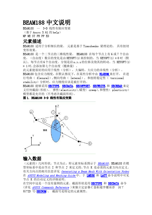
BEAM188中文说明BEAM188 —3-D 线性有限应变梁(基于Ansys 5.61的help)MP ME ST PR PP ED元素描述BEAM188 适用于分析细长的梁。
元素是基于Timoshenko 梁理论的。
具有扭切变形效果。
BEAM188 是一个二节点的三维线性梁。
BEAM188 在每个节点上有6或7个自由度,(自由度)数目的变化是由KEYOPT(1)来控制的。
当 KEYOPT(1) = 0时 (默认), 每节点有6个自由度。
分别是沿x,y,z的位移及绕其的转动。
当 KEYOPT(1) = 1时,会添加第七个自由度 (翘曲量) 。
此元素能很好的应用于线性(分析),大偏转,大应力的非线性(分析)。
BEAM188包含应力刚度,在默认情况下,在某些分析中由NLGEOM来打开。
在进行弯曲( flexural),侧向弯曲( lateral), 和扭转稳定性( torsional stability)分析时,应力刚度应该是被打开的。
BEAM188 能够采用SECTYPE, SECDATA, SECOFFSET, SECWRITE,和SECREAD来定义任何截面(形状)。
. 弹性(elasticity),蠕变( creep),和塑性( plasticity)模型都是允许的 (不考虑次截面形状)。
图1. BEAM188 3-D 线性有限应变梁输入数据(元素的)几何形状,节点为止,即元素坐标系图示于BEAM188。
BEAM188在模型坐标系中是由节点 I 和节点 J 来定义的。
节点 K 是必需的元素方向点定义。
有关方向点的相关信息详见Generating a Beam Mesh With Orientation Nodes 在ANSYS Modeling and Meshing Guide中。
于LMESH和LATT命令说明中可见节点 K 的自动定义的详细说明。
在空间中这是一个没有量纲的元素。
截面形状是用SECTYPE和SECDATA命令(详见ANSYS Commands Reference )来独立定宓摹C恳桓鼋孛嫘巫淳囟ㄒ桓?ID 号(SECNUM)。
MAX188DCPP+;MAX186DCPP+;MAX186DCWP+;MAX186DCAP+;MAX186DEWP+;中文规格书,Datasheet资料
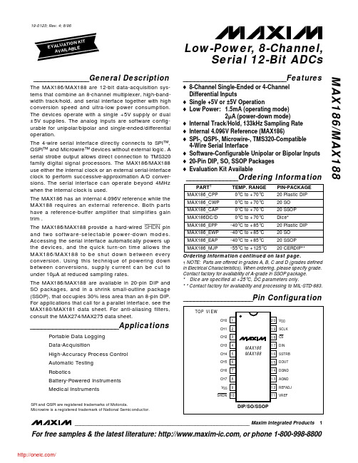
o 8-Channel Single-Ended or 4-Channel Differential Inputs
o Single +5V or ±5V Operation o Low Power: 1.5mA (operating mode)
2µA (power-down mode) o Internal Track/Hold, 133kHz Sampling Rate o Internal 4.096V Reference (MAX186) o SPI-, QSPI-, Microwire-, TMS320-Compatible
-40°C to +85°C
20 Plastic DIP
MAX186_EWP -40°C to +85°C
Hale Waihona Puke 20 SOMAX186_EAP
-40°C to +85°C
20 SSOP
MAX186_MJP
-55°C to +125°C 20 CERDIP**
Ordering Information continued on last page. † NOTE: Parts are offered in grades A, B, C and D (grades defined in Electrical Characteristics). When ordering, please specify grade. Contact factory for availability of A-grade in SSOP package. * Dice are specified at +25°C, DC parameters only. * * Contact factory for availability and processing to MIL-STD-883.
蜚声功放说明书
5. 安装孔 用于安装到机柜时固定用。
6. 通道1的音量控制器 功放工作于立体声或并接模式时由此控制器控制通道1的输出电平,功放工作于桥接模式时由此控制器控 制输出电平,此时通道2的音量控制器失效。
7. 保护指示 当此指示灯亮,处于保护状态,方便找出问题所在。 指示的保护功能有:削峰压限保护、过热保护、过载保护、短路保护、直流保护功能。
11电压增益频率响应总谐波失真转换速率阻尼系数动态范围信噪比输入灵敏度输入阻抗平衡不平衡输出级电路类型保护功能高通滤波器低通滤波器散热气流方向输入电压频率外箱尺寸mm重量压限直流短路开关机零冲击开机软启动vhf甚高频保护压限直流短路开关机零冲击开机软启动从功放面板进风23kg29kg29kg33kg35kg38kg33kgl620xw585xh210max1200max2400max3600max4300max7200max7800650wx21250wx2450wx2675wx2800wx2975wx21650wx21950wx2520wx2450wx2300wx21100wx2max4800830wx21250wx2900w1350w1600w1950w3300w3900w2500w620wx21000wx21200wx21400wx22160wx22700wx21850wx2桥接功率1240w2000w2400w2800w43200w5400w3700wmax系列技术参数12注意
2. TRS输入座(平衡或不平衡)。连接到上一级的周边处理设备。 3. 直通插座
与XLR 输入并联,提供一个与输入信号一样的输出信号,用此平衡插座连接到另一台设备。 (仅限于MAX4300、MAX4800、MAX7200、MAX7800) 4. 输入灵敏度开关 此开关用于选择功放的输入灵敏度:0.775V、1.0V及1.4V。(仅限于MAX4300、MAX4800、MAX7200、 MAX7800)。 5. 工作模式选择开关 用此开关去选择功放的工作模式: STEREO/立体声:两个通道完全独立。 PARALLEL/并接:信号共用通道1输入,音量独立控制,输出独立。 BRIDGE/桥接:信号共用通道1输入,音量由通道1控制,输出接通道1的SPEAKON。当使用到该工作模式 时,背板的指示灯亮。 注意:具体见下页的接线图。 6. 150Hz低通滤波器开关 若系统中需要推动超低音的音箱时,将开关拨到“ON”的位置可以滤掉150Hz以上的信号,直接使用功放 推动超低音的音箱,无需外加电子分频器。(仅限于MAX4300、MAX4800、MAX7200、MAX7800) 7. 音箱螺旋座输出 这是功放螺旋座的输出端。1+接喇叭的正端,1-接喇叭的负端,桥接时1+接喇叭的正端、2+接喇叭的负端。 8. 喇叭接线柱输出 这是功放喇叭接线柱的输出端。红色接喇叭的正端,黑色接喇叭的负端,桥接时只使用红色接喇叭的正端。 9. 保险管座 此保险管座内装由标准规格的保险管,用于故障时保护功放,如果功放已经接上电源待机指示灯没有点亮 时,请检查保险管的情况,如发现保险管已熔掉,在故障排除后,必须更换同一规格的保险管。 10. 散热的气流入口,不要有任何东西堵住。
AXP188

DATASHEETV1.01 Mar. 29 2010AXP188 Single Cell Li-Battery and Power System Management ICKrossPower© 2008 KrossPower Limited - All rights reserved目录目录目录 (1)1.概述 (3)2.特性 (4)3.典型应用电路图 (5)4.极限参数(ABSOLUTE MAXIMUM RATINGS) (6)5.电气特性(Electrical Characteristics) (7)6.典型特性(Typical Characteristics) (10)7.管脚定义(Pin Description) (18)8.功能框图(Functional Block Diagram) (20)9.控制和操作(Control and Operating) (21)9.1 Host Control模式 (21)9.2 开关机和复位 (Power On/Off & Reset) (21)9.3电源通路管理(IPS) (22)9.4 自适应的充电器(Adaptive Charger) (24)9.5 多路电源输出 (Multi-Power Outputs) (28)9.6 电池电量测量(Fuel Gauge) (30)9.7 HOST接口及中断 (Host Interface and IRQ) (31)9.8 寄存器 (Registers) (32)寄存器列表 (32)寄存器1:电源状态指示 (33)寄存器2:IPS设置 (33)寄存器3:关机控制、充电结束条件设置、充电状态、电池检测控制,DCIN状态 (34)存器4:充电控制1 (35)寄存器5:充电控制2 (35)寄存器6:PEK振荡频率设置 (36)寄存器7:中断使能1 (36)寄存器8:中断使能2 (37)寄存器9:中断使能3 (37)寄存器10:中断状态1 (38)寄存器11:中断状态2 (38)寄存器12:中断状态3 (39)寄存器13:Vendor Used (39)寄存器14:DC-DC模式控制 (39)寄存器15:DC-DC1、DC-DC2输出电压设置 (40)寄存器16:LDO2、DC-DC3、LDO3输出电压设置 (40)寄存器17:SW1、SW2、LDO4、LDO5开关控制及LDO4、LDO5电压设置 (41)寄存器18:ADC采样的电池电压数据 (41)寄存器19:ADC采样的电池电流数据 (41)寄存器20:ADC采样的DCIN电压数据 (41)寄存器21:ADC采样的DCIN电流数据 (42)寄存器22:ADC开关控制 (42)寄存器23:Vendor Used (42)寄存器24:功率器件开关控制 (43)寄存器25:数据缓存区1 (43)寄存器26:数据缓存区2 (43)10. 封装(Package) (44)<END> (45)1.概述AXP188是高度集成的电源系统管理芯片,针对单芯锂电池(锂离子或锂聚合物)且需要多路电源转换输出的应用,提供简单易用而又可以灵活配置的完整电源解决方案,充分满足目前日益复杂的应用处理器SOC 应用系统对于电源相对复杂而精确控制的要求。
ANSYS中BEAM188的使用方法

该单元输入摘要载于“BEAM188输入汇总”。
BEAM188横断面
BEAM188可以与这些横截面类型相关联:
它定义梁截面(SECTYPE,BEAM)的几何结构标准库部分类型或用户的网格。梁的材料被定义成元素的属性(MAT),或作为第积累部分(用于多材料的横截面)。
如果该部分被分配子形状ASEC,只有广义应力和应变(轴向力,弯矩,横剪,曲率,以及剪切应变)可用于输出。3 -D等高线图和变形形状都没有。该ASEC亚型显示只是一道薄薄的长方形来验证梁的方向。
BEAM188是用于分析组合梁有帮助(即,那些制成的两片或多片材料连接在一起形成一个单一的,实心光束)。件被认为是完全粘结在一起,因此,光束表现为一个单一的部件。
的自由度的数目取决于KEYOPT的值(1)。当KEYOPT(1)= 0(默认),六个自由度发生在每一个节点。这些包括在x,y和z方向和旋转围绕x,y和z方向的平移。当KEYOPT(1)= 1,自由度(横截面的翘曲)的第七度也被认为是。
梁元件是在空间中的一维的线元素。经由SECTYPE和SECDATA命令分开设置的横截面细节。(见梁分析和横截面的结构分析指南中的详细信息)。A节与梁单元通过指定截面号(SECNUM)相关联。A节数是一个独立的元素属性。除了恒定的横截面,你也可以通过使用锥选项上SECTYPE命令定义一个锥形截面(见定义变截面梁)。
BEAM188
3 - D 2节点梁
: > < > < > < > PP EME MFS
产品限制
BEAM188元素说明
BEAM188适用于分析细长到中等粗短/厚梁结构。该元素是基于Timoshenko梁理论,其中包括剪切变形效果。该元件提供无节制的翘曲和横截面的受限制翘曲的选项。
产品说明书_中英文对照版_
Hole Size
A
In sheet
C
E±
板孔尺寸 (max) 0.10 (max)
+.003
.030
.038
.166
.165 .25
.054
.030
.038
.166
.165 .25
.054
.087
.030
.038
.1875
.187 .28
.054
.087
.030
.038
.213
.212 .31
.054
A (max)
0
0.8-1.0
0.77
M2x0.4
S
CLS
1
1.0
0.97
2
1.4
1.38
0
0.8-1.0
0.77
M2.5x0.45
S
CLS
1
1.0
0.97
2
1.4
1.38
0
0.8-1.0
0.77
M3x0.5
S
CLS
1
1.0
0.97
2
1.4
1.38
0
0.8-1.0
0.77
M3.5x0.6
S
CLS
1
1.0
M10x1.5
S
CLS
2
3.18
地址:深圳市宝安区福永镇和平骏丰工业区 A2 栋 电话:0755-27328881 29590005 29590006 传真:0755-27328885 网址: E-mail: sales@
2.21 3.05
.060 .090 .060 .090 .060 .090 .060 .090 .060 .090 .120 .151 .182
ansys中的Beam188单元中文说明
BEAM188中文说明BEAM188 —3-D 线性有限应变梁(基于Ansys 5.61的help)MP ME ST PR PP ED元素描述BEAM188 适用于分析细长的梁。
元素是基于Timoshenko 梁理论的。
具有扭切变形效果。
BEAM188 是一个二节点的三维线性梁。
BEAM188 在每个节点上有6或7个自由度,(自由度)数目的变化是由KEYOPT(1)来控制的。
当 KEYOPT(1) = 0时 (默认), 每节点有6个自由度。
分别是沿x,y,z的位移及绕其的转动。
当 KEYOPT(1) = 1时,会添加第七个自由度 (翘曲量) 。
此元素能很好的应用于线性(分析),大偏转,大应力的非线性(分析)。
BEAM188包含应力刚度,在默认情况下,在某些分析中由NLGEOM来打开。
在进行弯曲( flexural),侧向弯曲( lateral), 和扭转稳定性( torsional stability)分析时,应力刚度应该是被打开的。
BEAM188 能够采用SECTYPE, SECDATA, SECOFFSET, SECWRITE,和SECREAD来定义任何截面(形状)。
. 弹性(elasticity),蠕变( creep),和塑性( plasticity)模型都是允许的 (不考虑次截面形状)。
图1. BEAM188 3-D 线性有限应变梁输入数据(元素的)几何形状,节点为止,即元素坐标系图示于BEAM188。
BEAM188在模型坐标系中是由节点 I 和节点 J 来定义的。
节点 K 是必需的元素方向点定义。
有关方向点的相关信息详见Generating a Beam Mesh With Orientation Nodes 在ANSYS Modeling and Meshing Guide中。
于LMESH和LATT命令说明中可见节点 K 的自动定义的详细说明。
在空间中这是一个没有量纲的元素。
截面形状是用SECTYPE和SECDATA命令(详见ANSYS Commands Reference )来独立定宓摹C恳桓鼋孛嫘巫淳囟ㄒ桓?ID 号(SECNUM)。
MAX667中文资料

_______________General DescriptionThe MAX667 low-dropout, positive, linear voltage regu-lator supplies up to 250mA of output current. With no load, it has a typical quiescent current of 20µA. At 200mA of output current, the input/output voltage differ-ential is typically 150mV. Other features include a low-voltage detector to indicate power failure, as well as early-warning and low-dropout detectors to indicate an imminent loss of output voltage regulation. A shutdown control disables the output and puts the circuit into a low quiescent-current mode.The MAX667 employs Dual Mode™ operation. One mode uses internally trimmed feedback resistors to pro-duce +5V. In the other mode, the output may be varied from +1.3V to +16V by connecting two external resistors.The MAX667 is a pin-compatible upgrade to the MAX666 in most applications where the input voltages are above +3.5V. Choose the MAX667 when high out-put currents and/or low dropout voltages are desired,as well as for improved performance at higher temperatures.________________________ApplicationsBattery-Powered DevicesPagers and Radio Control Receivers Portable Instruments Solar-Powered Instruments____________________________Featureso 350mV Max Dropout at 200mA o 250mA Output Currento Normal Mode: 20µA Typ Quiescent Current Shutdown Mode: 0.2µA Typ Quiescent Current o Low-Battery Detectoro Fixed +5V (Min Component Count) or Adjustable Output o +3.5V to +16.5V Input o Dropout Detector Output o 10µF Output Capacitor______________Ordering InformationMAX667+5V/Programmable Low-DropoutVoltage Regulator________________________________________________________________Maxim Integrated Products 1__________________Pin Configuration__________Typical Operating Circuit Call toll free 1-800-998-8800 for free samples or literature.19-3894; Rev 3; 10/94* Contact factory for dice specifications.TM Dual Mode is a trademark of Maxim Integrated Products.M A X 667+5V/Programmable Low-Dropout Voltage Regulator 2_______________________________________________________________________________________ABSOLUTE MAXIMUM RATINGSStresses beyond those listed under “Absolute Maximum Ratings” may cause permanent damage to the device. These are stress ratings only, and functional operation of the device at these or any other conditions beyond those indicated in the operational sections of the specifications is not implied. Exposure to absolute maximum rating conditions for extended periods may affect device reliability.Input Supply Voltage ...........................................................+18V Output Short Circuited to Ground.........................................1sec LBO Output Sink Current....................................................50mA LBO Output Voltage...............................................GND to V OUT SHDN Input Voltage....................................-0.3V to (V IN + 0.3V)Input Voltages LBI, SET................................-0.3V to (V IN - 1.0V)Continuous Power DissipationPlastic DIP (derate 9.09mW/°C above +70°C)............727mWSO (derate 5.88mW/°C above +70°C).........................471mW CERDIP (derate 8.00mW/°C above +70°C).................640mW Operating Temperature RangesMAX667C_A........................................................0°C to +70°C MAX667E_A.....................................................-40°C to +85°C MAX667MJA..................................................-55°C to +125°C Storage Temperature Range.............................-65°C to +160°C Lead Temperature (soldering, 10sec).............................+300°CNote 1:Dropout Voltage is V IN -V OUT when V OUT falls to 0.1V below its value at V IN = V OUT + 2V.Note 2:Short-Circuit Current is pulse tested to maintain junction temperature. Short-circuit duration is limited by package dissipation.ELECTRICAL CHARACTERISTICS(GND = 0V, V = +9V, V = +5V, C1 = 10µF, unless otherwise noted.)MAX667+5V/Programmable Low-DropoutVoltage Regulator3100011101001000DROPOUT VOLTAGE vs. LOAD CURRENT10100M A X 667-F g T O C 1LOAD CURRENT (mA)D R O P O U T V O L T A GE (m V )QUIESCENT CURRENT vs. LOAD CURRENTQ U I E S C E N T C U R R E N T (µA )10100100010,000100,0000.010.11101001000LOAD CURRENT (mA)1000105015025010100100200DD OUTPUT CURRENTvs. INPUT-OUTPUT DIFFERENCED D O U T P U T C U R RE N T (µA )INPUT-OUTPUT DIFFERENCE (mV)__________________________________________Typical Operating Characteristics_____________________Pin Description_______________Detailed DescriptionFigure 1 shows a micropower bandgap reference, an error amplifier, a PNP pass transistor, and two com-parators as the main elements of the MAX667. One comparator, C1, selects the fixed 5V or adjustable operation with an external voltage divider. The other comparator, C2, is a low-battery detector.The bandgap reference, which is trimmed to 1.22V,connects internally to one input of the error amplifier,A1. The feedback signal from the regulator output sup-plies the other input of A1 from either an on-chip volt-age divider or two external resistors. When SET is grounded, the internal divider provides the error ampli-fier feedback signal for a fixed 5V output. When SET is more than 50mV above ground, the error amplifier’s input switches directly to SET while an external resistor divider from OUT determines the output voltage.A second comparator, C2, compares the LBI input to the internal reference voltage. LBO is an open-drain FET connected to GND. The low-battery threshold can also be set with a voltage divider at LBI. In addition, the MAX667 has a shutdown input (SHDN) that disables the load and the device while reducing quiescent cur-rent when it is pulled high.+5V OutputFigure 2 shows the connection for a fixed 5V output.The SET input is grounded, and no external resistors are required. Figure 3 shows adjustable output opera-tion. R1 and R2 set the output voltage. SHDN should be grounded if not used.(T A = +25°C, unless otherwise noted.)M A X 667+5V/Programmable Low-Dropout Voltage Regulator 4_______________________________________________________________________________________Figure 2. Fixed +5V RegulatorFigure 3. Adjustable Output and Low-Battery DetectorOutput-Voltage SelectionIf SET is connected to a resistive voltage divider (Figure 3), the output voltage is set by the equation:V OUT = V SET x (R1 + R2) / R1,where V SET = 1.22VTo simplify resistor selection:R2 = R1 x (V OUT / V SET - 1)Since the input bias current at SET has a maximum value of 10nA, relatively large values can be used for R1 and R2 with no loss of accuracy. 1M Ωis a typical value for R1. The V SET tolerance is less than ±25mV.This allows the output to be preset without trim pots,using only fixed resistors in most cases. However,when resistor values greater than 1M Ωare used, pay special attention to printed circuit board leakage that can introduce error at the SET input.Shutdown (Standby) ModeSHDN puts the device into standby mode to conserve power. When this pin is held low, the IC operates nor-mally. If it is driven above 1.5V, the chip shuts down.Quiescent current of the MAX667 is then reduced to less than 1µA, and OUT turns off.Note that the voltage for SHDN must never be more than 0.3V higher than V IN .Low-Battery FunctionThe MAX667 contains circuitry for low-battery detec-tion. If the voltage at LBI falls below the regulator’s internal reference (1.22V), LBO, an open-drain output,sinks current to GND. The threshold can be set to any level above the reference voltage by connecting a resistive divider to LBI based on the equation:R3 = R4 x (V BATT / V LBI - 1)where V BATT is the desired threshold of the low-battery detector, and R3 and R4 are the LBI input divider resistors.Since LBI input current is no more than 10nA, high val-ues for R3 and R4 minimize loading. If V OUT is 5V, a 5.5V low-battery threshold can be set using 8.2M Ωfor R3 and 2.4M Ωfor R4. When resistor values greater than 1M Ωare used, pay special attention to PC board leakage that can introduce error at the LBI input.When the voltage at LBI is below the internal threshold,LBO sinks current to GND. A pull-up resistor of 10k Ωor more connected to OUT can be used with this pin when driving CMOS circuits. Any pull-up resistor connected to LBO should not be returned to a voltage source greater than V OUT . When LBI is above the threshold or the MAX667 is in SHDN mode, the LBO output is off.Dropout DetectorThe minimum input-output differential, or dropout volt-age, determines the regulator’s lowest usable input voltage. In battery-operated systems, this determines the useful end-of-life battery voltage. The MAX667 fea-tures very low dropout voltage (see Electrical Characteristics ). In addition, the MAX667 has a dropout detector output, DD, that changes as the dropout volt-age approaches its limit. DD is an open collector of a PNP transistor. The dropout voltage and the dropout detector both depend on the output current and tem-perature. When the input voltage is more than 300mV above the output voltage, the dropout detector will not conduct. As the differential decreases below 300mV,the DD source current increases abruptly. This current signals a warning that regulation is about to be lost.Connecting a resistor (typically 100k Ω) from DD to ground develops a voltage that can be monitored by analog circuits or changed to digital levels by a com-parator. LBI may be used for this purpose.__________Applications InformationOutput CapacitorAs with all PNP output regulators, an output capacitor (C1, Figure 2) is required to maintain stability. 10µF is recommended. To ensure stability, the output-capacitor ESR must be sufficiently high. Figure 4 shows the mini-mum required output-capacitor ESR for a given temper-ature. Alternatively, a resistor may be added in series with the output capacitor (Figure 5); the sum of the out-MAX667+5V/Programmable Low-DropoutVoltage Regulator_______________________________________________________________________________________5Figure 4. Minimum Required Output-Capacitor ESR vs.TemperatureM A X 667minimum, meet the requirements shown in Figure 4.An upper limit to the output-capacitor ESR is important only if step changes to the load are anticipated. Higher ESR results in higher-amplitude output-voltage tran-sients when the output current is varied. A Sanyo OS-CON capacitor, whose ESR is nearly flat over tem-perature (and is low to begin with), in series with the appropriate resistor ensures the best load-transient performance. A less expensive alternative is to use a tantalum capacitor in series with the resistor.In most cases, inexpensive aluminum-electrolytic capacitors work well with the MAX667 over their entire temperature range, having sufficient ESR to ensure sta-bility without the need for a series resistor. The ESR of aluminium electrolytics rises, often dramatically, as temperature decreases. For surface-mount applica-tions, certain tantalum capacitors have sufficient ESR;an example is the TAJB106K016 chip capacitor made by AVX (phone: (803) 448-9411, fax: (803) 448-1943).Battery DrainThe MAX667 uses a PNP output transistor. When the input voltage falls below the desired output voltage, the+5V/Programmable Low-Dropout Voltage Regulator 6_______________________________________________________________________________________Figure 7. Connection for Minimum Quiescent Current Near DropoutFigure 8. Quiescent Current Below Dropout for Circuit of Figure 2PNP transistor is turned on fully as regulation is lost.Even with a load current of a few microamperes, the base current will be driven above 5mA. Figure 8 shows how this base current may be significant.Consequently, a mostly discharged battery can be fur-ther discharged at end-of-life.Figure 6 shows how this condition can be modified by connecting DD to SHDN with a 47k Ωresistor, R1, par-alleled with a 0.1µF capacitor to GND. This modifica-tion reduces the no-load quiescent current to approximately 160µA when dropout is reached (Figure 9), but increases the dropout voltage by about 0.1V.The output voltage drops to approximately 3V once DD begins to activate SHDN, but it does not fall to zero because SHDN is only partially activated.A second alternate connection (Figure 7) further reduces quiescent current near the dropout voltage,compared to the circuit in Figure 6. The output must be set with external resistors (R1, R2), so DD lowers the output voltage as the input voltage falls by sourcing current into SET via R3. Quiescent current remains low for inputs down to 3.5V, and peaks before falling to 0at low input voltages. Although the current peak is higher than with the connection in Figure 6, this may be more useful because the quiescent current peaks at an input voltage well below the useful range of most batteries (Figure 9). Also, as IN falls below 5V, OUT tracks IN minus the dropout voltage. This connection still allows separate use of the SHDN input.Power DissipationThe MAX667 can regulate currents as high as 250mA and withstand input-output differential voltages as highas 15.2V, but not simultaneously. The maximum power dissipation is dependent on the package and the tem-perature (see Absolute Maximum Ratings ). Figure 10shows the maximum output current at various input-output differential voltages for the plastic DIP and SO packages. The MAX667 can withstand short-circuit loads up to 1 second.Operation from AC SourcesThe MAX667 is a micropower CMOS regulator intend-ed principally for battery operation. When operating from AC sources, consider power-supply ripple rejec-tion. The MAX667’s error amplifier produces very low gain bandwidth, and the input power-supply rejectionMAX667+5V/Programmable Low-Dropout_______________________________________________________________________________________7Voltage RegulatorFigure 9. Quiescent Current Below Dropout with Connections of Figures 6 and 7Figure 11. Output Response to +4V/100µs Input Step+10V +6V+5V OUTPUT +0.2V/divMaxim cannot assume responsibility for use of any circuitry other than circuitry entirely embodied in a Maxim product. No circuit patent licenses are implied. Maxim reserves the right to change the circuitry and specifications without notice at any time.8___________________Maxim Integrated Products, 120 San Gabriel Drive, Sunnyvale, CA 94086 (408) 737-7600©1994 Maxim Integrated ProductsPrinted USAis a registered trademark of Maxim Integrated Products.M A X 667+5V/Programmable Low-Dropout Voltage Regulator ratio (PSRR) is therefore not specified. Since the output must be connected to a 10µF or larger filter capacitor,the capacitor characteristics dominate the PSRR. Large values of input and output capacitors reduce the ripple. In addition, both DD and LBI/LBO can trigger on the lowest DC component of the ripple, particularly at high load currents. In the case of the low-battery detector,the ripple can be effectively filtered out by placing a capacitor to ground in parallel with the LBI input pin.The high resistance values that can be used for the voltage divider allow relatively small capacitance val-ues to form an effective lowpass filter at 120Hz. When power is first applied, however, this filter tends to hold LBO low longer than normal.Transient ConsiderationsThe low operating current and gain-bandwidth product of the internal reference and amplifier result in limited rejection of fast-step input changes. Negative-going steps, which occur in under 100µs, may turn off the out-put for several milliseconds. An input filter (nominally 10µF) is recommended if input changes greater than 1V and faster than 100µs (other than turn-on or turn-off)are anticipated. Figure 12 shows the output response to a 10mA/100mA instantaneous load step. The rela-tionship between output-capacitor ESR and load-tran-sient response is explained in the Output Capacitor section.___________________Chip TopographyOUTPUT CURRENT+5V OUTPUT0.1V/div100mA 10mA200µs/divFigure 12. Output Response to 10mA/100mA Load Step with 10µF Output Capacitor (1.5Ω ESR)LBO SETLBIOUTDDINSHDNGND0.107" (2.71mm)0.070" (1.78mm)TRANSISTOR COUNT: 65SUBSTRATE MUST BE LEFT UNCONNECTED元器件交易网。