04_DS and Algorithm_session_05
SDIO spec
f in eo nIn fio nI n fTechnical Committee SD Card Associationf in eo nIn fi ne o n I nf in eo nIRevision HistoryDate Version Changes compared to previous issueApril 3, 2006 1.10 Simplified Version Initial ReleaseFebruary 8, 20072.00(1) Added method to change bus speed (Normal Speed up to 25MHzand High Speed up to 50 MHz)(2) Operational Voltage Requirement is extended to 2.7-3.6V(3) Combine sections 12 (Physical Properties) and 13 (MechanicalExtensions) and add miniSDIO to the new section 13 (Physical Properties)(4) Add Embedded SDIO ATA Standard Function Interface Code (5) Reference of Physical Ver2.00 supports SDHC combo card. (6) Some typos in Ver1.10 are fixed.f in eo nIn fi ne o n I nf in eo nI Release of SD Simplified SpecificationThe following conditions apply to the release of the SD simplified specification ("Simplified Specification") by the SD Card Association. The Simplified Specification is a subset of the complete SD Specification which is owned by the SD Card Association.Publisher:SD Association2400 Camino Ramon, Suite 375 San Ramon, CA 94583 USA Telephone: +1 (925) 275-6615 Fax: +1 (925) 886-4870 E-mail: office@Copyright Holder: The SD Card AssociationNotes:This Simplified Specification is provided on a non-confidential basis subject to the disclaimers below. Any implementation of the Simplified Specification may require a license from the SD Card Association or other third parties.Disclaimers:The information contained in the Simplified Specification is presented only as a standard specification for SD Cards and SD Host/Ancillary products and is provided "AS-IS" without any representations or warranties of any kind. No responsibility is assumed by the SD Card Association for any damages, any infringements of patents or other right of the SD Card Association or any third parties, which may result from its use. No license is granted by implication, estoppel or otherwise under any patent or other rights of the SD Card Association or any third party. Nothing herein shall be construed as an obligation by the SD Card Association to disclose or distribute any technical information, know-how or other confidential information to any third party.f in eo nIn fi ne o n I nf in eo nConventions Used in This DocumentNaming ConventionsSome terms are capitalized to distinguish their definition from their common English meaning. Words not capitalized have their common English meaning.Numbers and Number BasesHexadecimal numbers are written with a lower case “h” suffix, e.g., FFFFh and 80h. Binary numbers are written with a lower case “b” suffix (e.g., 10b).Binary numbers larger than four digits are written with a space dividing each group of four digits, as in 1000 0101 0010b.All other numbers are decimal.Key WordsMay: Indicates flexibility of choice with no implied recommendation or requirement.Shall: Indicates a mandatory requirement. Designers shall implement such mandatory requirements to ensure interchangeability and to claim conformance with the specification.Should: Indicates a strong recommendation but not a mandatory requirement. Designers should give strong consideration to such recommendations, but there is still a choice in implementation.Application NotesSome sections of this document provide guidance to the host implementers as follows: Application Note:This is an example of an application note.f in eo nIn fi ne o n I nf in eo nTable of Contents1. General Description.................................................................................................................................1 1.1 SDIO Features....................................................................................................................................1 1.2 Primary Reference Document.............................................................................................................1 1.3 Standard SDIO Functions....................................................................................................................1 2. SDIO Signaling Definition........................................................................................................................2 2.1 SDIO Card Types................................................................................................................................2 2.2 SDIO Card modes...............................................................................................................................2 2.2.1 SPI (Card mandatory support).....................................................................................................2 2.2.2 1-bit SD Data Transfer Mode (Card Mandatory Support).............................................................2 2.2.3 4-bit SD Data Transfer Mode (Mandatory for High-Speed Cards, Optional for Low-Speed).........2 2.3 SDIO Host Modes...............................................................................................................................2 2.4 Signal Pins..........................................................................................................................................3 3. SDIO Card Initialization............................................................................................................................4 3.1 Differences in I/O card Initialization.....................................................................................................4 3.2 The IO_SEND_OP_COND Command (CMD5).................................................................................10 3.3 The IO_SEND_OP_COND Response (R4)........................................................................................11 3.4 Special Initialization considerations for Combo Cards.......................................................................12 3.4.1 Re-initialize both I/O and Memory..............................................................................................12 3.4.2 Using a Combo Card as SDIO only or SD Memory only after Combo Initialization....................12 3.4.3 Acceptable Commands after Initialization..................................................................................12 3.4.4 Recommendations for RCA after Reset.....................................................................................12 3.4.5 Enabling CRC in SPI Combo Card.............................................................................................14 4. Differences with SD Memory Specification..........................................................................................15 4.1 SDIO Command List.........................................................................................................................15 4.2 Unsupported SD Memory Commands...............................................................................................15 4.3 Modified R6 Response......................................................................................................................16 4.4 Reset for SDIO..................................................................................................................................16 4.5 Bus Width..........................................................................................................................................16 4.6 Card Detect Resistor.........................................................................................................................17 4.7 Timings..............................................................................................................................................17 4.8 Data Transfer Block Sizes.................................................................................................................18 4.9 Data Transfer Abort...........................................................................................................................18 4.9.1 Read Abort.................................................................................................................................18 4.9.2 Write Abort.................................................................................................................................18 4.10 Changes to SD Memory Fixed Registers..........................................................................................18 4.10.1 OCR Register.............................................................................................................................19 4.10.2 CID Register...............................................................................................................................19 4.10.3 CSD Register.............................................................................................................................19 4.10.4 RCA Register.............................................................................................................................19 4.10.5 DSR Register.............................................................................................................................19 4.10.6 SCR Register.............................................................................................................................19 4.10.7 SD Status...................................................................................................................................19 4.10.8 Card Status Register..................................................................................................................19 5. New I/O Read/Write Commands............................................................................................................21 5.1 IO_RW_DIRECT Command (CMD52)..............................................................................................21 5.2 IO_RW_DIRECT Response (R5)......................................................................................................22 5.2.1 CMD52 Response (SD modes)..................................................................................................22 5.2.2 R5, IO_RW_DIRECT Response (SPI mode).............................................................................23 5.3 IO_RW_EXTENDED Command (CMD53). (24)f in eo nIn fi ne o n I nf in eo nI 5.3.2 Special Timing for CMD53 Multi-Block Read..............................................................................25 6. SDIO Card Internal Operation................................................................................................................26 6.1 Overview...........................................................................................................................................26 6.2 Register Access Time........................................................................................................................26 6.3 Interrupts...........................................................................................................................................26 6.4 Suspend/Resume..............................................................................................................................27 6.5 Read Wait..........................................................................................................................................27 6.6 CMD52 During Data Transfer............................................................................................................27 6.7 SDIO Fixed Internal Map...................................................................................................................27 6.8 Common I/O Area (CIA)....................................................................................................................28 6.9 Card Common Control Registers (CCCR).........................................................................................28 6.10 Function Basic Registers (FBR)........................................................................................................35 6.11 Card Information Structure (CIS).......................................................................................................37 6.12 Multiple Function SDIO Cards...........................................................................................................37 6.13 Setting Block Size with CMD53.........................................................................................................37 6.14 Bus State Diagram............................................................................................................................38 7. Embedded I/O Code Storage Area (CSA).............................................................................................39 7.1 CSA Access.......................................................................................................................................39 7.2 CSA Data Format..............................................................................................................................39 8. SDIO Interrupts.......................................................................................................................................40 8.1 Interrupt Timing.................................................................................................................................40 8.1.1 SPI and SD 1-bit Mode Interrupts ..............................................................................................40 8.1.2 SD 4-bit Mode............................................................................................................................40 8.1.3 Interrupt Period Definition ..........................................................................................................40 8.1.4 Interrupt Period at the Data Block Gap in 4-bit SD Mode (Optional)..........................................40 8.1.5 Inhibited Interrupts (Removed Section)......................................................................................40 8.1.6 End of Interrupt Cycles...............................................................................................................40 8.1.7 Terminated Data Transfer Interrupt Cycle ..................................................................................41 8.1.8 Interrupt Clear Timing.................................................................................................................41 9. SDIO Suspend/Resume Operation........................................................................................................42 10. SDIO Read Wait Operation.....................................................................................................................43 11. Power Control.........................................................................................................................................44 11.1 Power Control Overview....................................................................................................................44 11.2 Power Control support for SDIO Cards.............................................................................................44 11.2.1 Master Power Control ................................................................................................................44 11.2.2 Power Selection.........................................................................................................................45 11.2.3 High-Power Tuples.....................................................................................................................45 11.3 Power Control Support for the SDIO Host.........................................................................................45 11.3.1 Version 1.10 Host.......................................................................................................................45 11.3.2 Power Control Operation............................................................................................................46 12. High-Speed Mode...................................................................................................................................47 12.1 SDIO High-Speed Mode....................................................................................................................47 12.2 Switching Bus Speed Mode in a Combo Card...................................................................................47 13. SDIO Physical Properties......................................................................................................................48 13.1 SDIO Form Factors...........................................................................................................................48 13.2 Full-Size SDIO ..................................................................................................................................48 13.3 miniSDIO...........................................................................................................................................48 14. SDIO Power.............................................................................................................................................48 14.1 SDIO Card Initialization Voltages......................................................................................................48 14.2 SDIO Power Consumption................................................................................................................48 15. Inrush Current Limiting..........................................................................................................................50 16. CIS Formats.. (51)f in eo nIn fi ne o n I nf in eo nI 16.2 Basic Tuple Format and Tuple Chain Structure.................................................................................51 16.3 Byte Order Within Tuples ..................................................................................................................51 16.4 Tuple Version ....................................................................................................................................52 16.5 SDIO Card Metaformat......................................................................................................................52 16.6 CISTPL_MANFID: Manufacturer Identification String Tuple..............................................................53 16.7 SDIO Specific Extensions..................................................................................................................53 16.7.1 CISTPL_FUNCID: Function Identification Tuple.........................................................................53 16.7.2 CISTPL_FUNCE: Function Extension Tuple..............................................................................54 16.7.3 CISTPL_FUNCE Tuple for Function 0 (common).......................................................................54 16.7.4 CISTPL_FUNCE Tuple for Function 1-7....................................................................................55 16.7.5 CISTPL_SDIO_STD: Function is a Standard SDIO Function.....................................................58 16.7.6 CISTPL_SDIO_EXT: Tuple Reserved for SDIO Cards...............................................................58 Appendix A.....................................................................................................................................................59 A.1 SD and SPI Command List....................................................................................................................59 Appendix B.....................................................................................................................................................61 B.1 Normative References...........................................................................................................................61 Appendix C.....................................................................................................................................................62 C.1 Abbreviations and Terms...................................................................................................................62 Appendix D.. (64)f in eo nIn fi ne o n I nf in eo nI Table of TablesTable 3-1 OCR Values for CMD5.....................................................................................................................10 Table 4-1 Unsupported SD Memory Commands.............................................................................................16 Table 4-2 R6 response to CMD3.....................................................................................................................16 Table 4-3 SDIO R6 Status Bits.........................................................................................................................16 Table 4-4 Combo Card 4-bit Control................................................................................................................17 Table 4-5 Card Detect Resistor States.............................................................................................................17 Table 4-6 is blanked.........................................................................................................................................17 Table 4-7 SDIO Status Register Structure .......................................................................................................20 Table 5-1 Flag data for IO_RW_DIRECT SD Response..................................................................................23 Table 5-2 IO_RW_ EXTENDED command Op Code Definition.......................................................................24 Table 5-3 Byte Count Values ...........................................................................................................................25 Table 6-1 Card Common Control Registers (CCCR).......................................................................................29 Table 6-2 CCCR bit Definitions........................................................................................................................34 Table 6-3 Function Basic Information Registers (FBR)....................................................................................35 Table 6-4 FBR bit and field definitions.............................................................................................................36 Table 6-5 Card Information Structure (CIS) and reserved area of CIA.............................................................37 Table 11-1 Reference Tuples by Master Power Control and Power Select......................................................45 Table 16-1 Basic Tuple Format........................................................................................................................51 Table 16-2 Tuples Supported by SDIO Cards..................................................................................................52 Table 16-3 CISTPL_MANFID: Manufacturer Identification Tuple.....................................................................53 Table 16-4 CISTPL_FUNCID Tuple.................................................................................................................53 Table 16-5 CISTPL_FUNCE Tuple General Structure.....................................................................................54 Table 16-6 TPLFID_FUNCTION Tuple for Function 0 (common)....................................................................54 Table 16-7 TPLFID_FUNCTION Field Descriptions for Function 0 (common).................................................54 Table 16-8 TPLFID_FUNCTION Tuple for Function 1-7..................................................................................55 Table 16-9 TPLFID_FUNCTION Field Descriptions for Functions 1-7.............................................................57 Table 16-10 TPLFE_FUNCTION_INFO Definition...........................................................................................57 Table 16-11 TPLFE_CSA_PROPERTY Definition...........................................................................................57 Table 16-12 CISTPL_SDIO_STD: Tuple Reserved for SDIO Cards................................................................58 Table 16-13 CISTPL_SDIO_EXT: Tuple Reserved for SDIO Cards.................................................................58 Table A-14 SD Mode Command List................................................................................................................59 Table A-15 SPI Mode Command List (60)f in eo nIn fi ne o n I nf in eo nI Table of FiguresFigure 2-1 Signal connection to two 4-bit SDIO cards.......................................................................................3 Figure 3-1 SDIO response to non-I/O aware initialization..................................................................................4 Figure 3-2 Card initialization flow in SD mode (SDIO aware host)....................................................................7 Figure 3-3 Card initialization flow in SPI mode (SDIO aware host)....................................................................9 Figure 3-4 IO_SEND_OP_COND Command (CMD5).....................................................................................10 Figure 3-5 Response R4 in SD mode...............................................................................................................11 Figure 3-6 Response R4 in SPI mode..............................................................................................................11 Figure 3-7 Modified R1 Response....................................................................................................................11 Figure 3-8 Re-Initialization Flow for I/O Controller...........................................................................................13 Figure 3-9 Re-Initialization Flow for Memory controller ...................................................................................13 Figure 5-1 IO_RW_DIRECT Command...........................................................................................................21 Figure 5-2 R5 IO_RW_DIRECT Response (SD modes)..................................................................................22 Figure 5-3 IO_RW_DIRECT Response in SPI Mode.......................................................................................23 Figure 5-4 IO_RW_EXTENDED Command.....................................................................................................24 Figure 6-1 SDIO Internal Map..........................................................................................................................28 Figure 6-2 State Diagram for Bus State Machine (38)f in eo nIn fi ne o n I nf in eo nI 1. General DescriptionThe SDIO (SD Input/Output) card is based on and compatible with the SD memory card. This compatibility includes mechanical, electrical, power, signaling and software. The intent of the SDIO card is to provide high-speed data I/O with low power consumption for mobile electronic devices. A primary goal is that an SDIO card inserted into a non-SDIO aware host shall cause no physical damage or disruption of that host or it’s software. In this case, the SDIO card should simply be ignored. Once inserted into an SDIO aware host, the detection of the card proceeds via the normal means described in this specification with some extensions. In this state, the SDIO card is idle and draws a small amount of power (15 mA averaged over 1 second). During the normal initialization and interrogation of the card by the host, the card identifies itself as an SDIO card. The host software then obtains the card information in a tuple (linked list) format and determines if that card’s I/O function(s) are acceptable to activate. This decision is based on such parameters as power requirements or the availability of appropriate software drivers. If the card is acceptable, it is allowed to power up fully and start the I/O function(s) built into it.1.1 SDIO Features• Targeted for portable and stationary applications• Minimal or no modification to SD Physical bus is required • Minimal change to memory driver software• Extended physical form factor available for specialized applications • Plug and play (PnP) support• Multi-function support including multiple I/O and combined I/O and memory • Up to 7 I/O functions plus one memory supported on one card. • Allows card to interrupt host• Operational Voltage range: 2.7-3.6V (Operational Voltage is used for Initialization) • Application Specifications for Standard SDIO Functions. • Multiple Form Factors:• Full-Size SDIO • miniSDIO1.2 Primary Reference DocumentThis specification is based on and refers extensively to the SDA document:SD Memory Card SpecificationsPart 1 PHYSICAL LAYER SPECIFICATION Version 2.00 May 9, 2006The reader is directed to this document for more information on the basic operation of SD cards. In addition, other documents are referenced in this specification. A complete list can be found in appendix B.1.This specification can apply to any released versions of Physical Layer Specification after Version 2.00.1.3 Standard SDIO FunctionsAssociated with the base SDIO specification, there are several Application Specifications for Standard SDIO Functions. These common functions such as cameras, Bluetooth cards and GPS receivers have a standard register interface, a common operation method and a standard CIS extension. Implementation of the standard interfaces are optional for any card vendor, but compliance with the standard allows the use of standard drivers and applications which will increase the appeal of these cards to the consumer. Full information on these standard interfaces can be found in the Application Specifications for Standard SDIO Functions maintained by the SDA.。
普林斯顿算法
普林斯顿算法
普林斯顿算法是一种用于解决最短路径问题的一种经典算法,也称为迪杰斯特拉算法。
它是一种贪婪算法,逐步构建最短路径树,从起始节点开始,依次选择与当前节点距离最近的节点,并更新该节点到其他节点的距离。
通过不断选择最短路径上的节点,最终得到起点到各个节点的最短路径。
普林斯顿算法的基本步骤如下:
1. 创建一个距离列表distances,用于保存起始节点到各个节点的最短距离,初始值为无穷大(表示未知路径)。
2. 创建一个前驱列表predecessors,用于保存路径上每个节点
的前驱节点,初始值为None。
3. 将起始节点的距离设置为0,即distances[start_node] = 0。
4. 选择距离最短且未被访问的节点作为当前节点。
5. 更新当前节点到邻居节点的距离,如果新的距离比原来的距离小,则更新距离和前驱节点。
6. 标记当前节点为已访问。
7. 重复步骤4-6直到所有节点都被访问。
8. 根据distances和predecessors构建最短路径。
普林斯顿算法的时间复杂度为O(V^2),其中V为节点数。
它
适用于处理节点数不太大的图,但在节点数非常大时,性能可能较差。
为了提高效率,还有一种优化的算法称为堆优化的迪杰斯特拉算法,它使用优先队列来选择最短距离的节点,使得时间复杂度降为O((V+E)logV),其中E为边数。
TLS参数术语介绍
TLS参数术语介绍TLS(Transport Layer Security)是一种用于保护网络通信的协议,它在传输层上提供了安全的数据传输。
TLS使用了多种加密算法和安全机制来确保通信的保密性、完整性和身份验证。
在TLS中有一些重要的参数和术语,下面将对这些参数和术语进行介绍。
1. 密码套件(Cipher Suite)密码套件是指TLS使用的加密算法和密钥交换算法的集合。
一个密码套件通常包括对称加密算法、散列算法、密钥交换算法和数字签名算法等。
在TLS握手过程中,客户端和服务器会协商选择一个适合双方的密码套件进行通信。
2. 对称加密算法(Symmetric Encryption Algorithm)对称加密算法是指在加密和解密时使用相同的密钥的算法。
在TLS中常用的对称加密算法有AES(Advanced Encryption Standard)、3DES (Triple Data Encryption Algorithm)和RC4(Rivest Cipher 4)等。
3. 散列算法(Hash Algorithm)散列算法是将任意长度的数据映射到一个固定长度的结果的算法。
在TLS中,散列算法用于计算消息摘要,以确保数据的完整性和一致性。
常用的散列算法有MD5(Message Digest Algorithm 5)和SHA(Secure Hash Algorithm)等。
4. 密钥交换算法(Key Exchange Algorithm)密钥交换算法是用于在通信双方之间安全地传递秘密密钥的算法。
在TLS中,密钥交换算法可以分为两种类型:非对称密钥交换算法和对称密钥交换算法。
常用的非对称密钥交换算法有RSA(Rivest-Shamir-Adleman)和Diffie-Hellman等,而常用的对称密钥交换算法有Pre-Shared Key(PSK)和Elliptic Curve Cryptography(ECC)等。
NetSDK编程指导手册(大华)
目的
欢迎使用 NetSDK(以下简称 SDK)编程指导手册。 SDK 是软件开发者在开发网络硬盘录像机、网络视频服务器、网络摄像机、网络球机和智能设备 等产品监控联网应用时的开发套件。
本文档详细描述了开发包中各个函数的功能、接口以及函数之间的调用关系,并提供了代码示例。
符号约定
在本文档中可能出现下列标志,它们所代表的含义如下。
1.1 概述 .............................................................................................................................................. 1 1.2 环境要求 ....................................................................................................................................... 2 第 2 章 主要功能 ...................................................................................................................................... 3 2.1 SDK 初始化 ................................................................................................................................... 3
ctf 不明文件解题思路

解题思路:
1.文件类型识别:首先,我们需要确定这个不明文件的类型。
可以通过文件的
扩展名或者使用工具如file命令来进行识别。
2.静态分析:如果文件是可执行文件,我们可以使用静态分析工具来查看其反
汇编代码、导入表、字符串等,以获取更多信息。
3.动态分析:如果文件是动态链接库(DLL)或共享对象(SO),我们可以尝
试加载到调试器中,观察其在运行时的行为。
4.搜索已知漏洞:如果文件是已知的恶意软件或利用了已知漏洞,我们可以使
用搜索引擎或漏洞数据库进行查询。
5.网络通信:如果文件是网络相关的,我们可以观察其网络通信行为,例如发
送了哪些数据、连接了哪些服务器等。
6.权限提升:如果文件具有系统级权限,我们可以尝试利用其他系统漏洞来提
升权限,从而获取更多信息。
7.社工手段:如果以上方法都无法获取更多信息,我们可以尝试通过社交工程
手段来获取更多背景信息。
8.报告输出:最后,整理所有的信息,形成详细的报告,包括文件类型、分析
过程、可能的风险等。
Arduino编程参考手册中文版(带目录适合打印)
! (逻辑非)
指针运算符
* 指针运算符
& 地址运算符
位运算
& (位与)
| (位或)
^ (位异或)
~ (位非)
<< (左移)
>> (右移)
复合运算符
++ (自加)
-- (自减)
+= (复合加)
-= (复合减)
*= (复合乘)
/= (复合除)
&= (复合与)
|= (复合或)
范围
HIGH | LOW
int checkSensor(){
if (analogRead(0) > 400) {
return 1;
else{
return 0;
}
}
return关键字对测试一段代码很方便,不需“注释掉”大段的可能是错误的代码。
void loop(){
//在此测试代码是个好想法
return;
// 这里是功能不正常的代码
for
for语句
描述
for语句用于重复执行被花括号包围的语句块。一个增量计数器通常被用来递增和终止循环。for语句对于任何需要重复的操作是非常有用的。常常用于与数组联合使用以收集数据/引脚。for循环的头部有三个部分:
for (初始化部分; 条件判断部分; 数据递增部分) {
//语句块
。。。
}
初始化部分被第一个执行,且只执行一次。每次通过这个循环,条件判断部分将被测试;如果为真,语句块和数据递增部分就会被执行,然后条件判断部分就会被再次测试,当条件测试为假时,结束循环。
示例:
for (x = 0; x < 255; x ++)
scoped session is already present -回复

scoped session is already present -回复Scoped Session: An In-Depth ExplanationIntroduction:In today's digital age, ensuring secure and reliable access to web applications has become crucial. One of the commonly used techniques to achieve this is by implementing a scoped session. In this article, we will explore what a scoped session is, its significance, and how it functions to enhance security and user experience. So, let's dive right in!What is a Scoped Session?A scoped session refers to a temporary and limited-duration session created for a user when they access a web application. It acts as a virtual container that holds data related to the user's session state, preferences, and other necessary information. Each user is assigned a unique session ID, which allows the server to identify and track the user's activity throughout their session.Why are Scoped Sessions Important?Scoped sessions play a vital role in ensuring the security and reliability of web applications. By creating a separate session for each user, the risk of unauthorized access and information leakage is significantly reduced. Scoped sessions restrict the scope of session data, preventing it from being accessed or manipulated by other users. These sessions also enhance the user experience by maintaining session state and preferences across multiple pages, allowing the user to seamlessly interact with the application.How Does a Scoped Session Work?1. Session Initialization:When a user accesses a web application, the server creates a unique session ID for that user. This session ID is either generated randomly or using an algorithm that ensures uniqueness. The session ID is then stored on the server and sent back to the user's browser as a cookie or parameter in the URL.2. Request Processing:As the user interacts with the web application, subsequent requests are sent to the server along with their session ID. Thisallows the server to retrieve the specific session associated with that user and process the request accordingly. The data stored within the session, such as authentication credentials or user preferences, can be accessed and utilized.3. Session Expiration:To prevent sessions from persisting indefinitely, scoped sessions are designed with an expiration mechanism. A session can have a fixed expiration time, such as after 30 minutes of inactivity, or it can be renewed with each user interaction. When a session expires, its data is typically deleted from the server, ensuring that sensitive information is not retained longer than necessary.4. Session Termination:Users can actively terminate their sessions by logging out or closing the browser. In such cases, the session ID is invalidated, and all associated session data is immediately removed from the server. This step is crucial in protecting user accounts from unauthorized access, especially when using shared or public computers.Best Practices for Implementing Scoped Sessions:1. Secure Session Management:Implement mechanisms to prevent session hijacking and unauthorized access. Use secure cookies that are not susceptible to tampering and employ encryption techniques to protect session data during transit.2. Validate User Input:Implement robust input validation to prevent injection attacks that may exploit session handling mechanisms. Ensure that session IDs cannot be manipulated through input fields.3. Secure Session Storage:Store session data securely on the server. Use encryption and access control techniques to protect the confidentiality and integrity of the stored data.4. Regular Session Expiration:Configure appropriate session timeout values to ensure sessions expire after an appropriate period of user inactivity. This helps reduce the risk of unauthorized access and ensures sensitive session data is not retained indefinitely.Conclusion:In summary, a scoped session is a crucial component of ensuring secure and uninterrupted access to web applications. By assigning a unique session ID to each user and limiting the data accessible within a session, scoped sessions enhance security and provide a seamless user experience. Developing and implementing scoped session mechanisms following best practices helps protect both users and applications from potential security threats.。
华为认证ICT工程师HCIA考试(习题卷10)

华为认证ICT工程师HCIA考试(习题卷10)说明:答案和解析在试卷最后第1部分:单项选择题,共105题,每题只有一个正确答案,多选或少选均不得分。
1.[单选题]通常提供应用运行开发环境的服务属于哪个层面的云服务?A)IaaSB)PaaSC)SaaS2.[单选题]下列关于Adhoc会议描述错误的是()A)在预约Adhoc会议时,需分别设置主席密码和会议激活密码。
B)Adhoc会议是通过终端侧激活会议并加入会议的一种会议方式。
C)使用Adhoc会议前需要新建Adhoc会议模板。
D)Adhoc会议在未激活的情况下,不占用MCU资源。
3.[单选题]以下关于华为Fusion Computer HA描述不正确的是()A)虚拟机的数据如果保存在共享存储內,发生故障时保存的数据不会失B)该功能支持虚拟机故障后自动重启C)系统周期检测虚拟机状态,当物理服务器故障引|起虚拟机故障时,系统可以将虚拟机迁移到其他物理服务器重新启动,保证虚拟机能够快速恢复D)管理员可以根据虚拟机的重要程度,设置不同的HA策略4.[单选题]以下不属于Tensor Flow 2.0的特点是?A)多核CPU加速B)分布式C)多语言D)多平台5.[单选题]下列RAID级别数据冗余能力最弱的是()A)RAID 1B)RAID 6C)RAID 0D)RAID 56.[单选题]如果应用层协议为Telnet,那么IPv4首部中Protocol字段取值为?A)17B)67C)53D)67.[单选题]在很多小文件场景下,Spark会起很多Task,当SQL逻辑中存在Shuffle操作时,会大大増加hash分桶数,严重影A)group byB)coalosceC)connectD)join8.[单选题]按华为云服务的划分,哪项云服务不属于计算云服务?A)弹性云服务B)弹性伸缩云服务C)虚拟私有云D)裸金属服务9.[单选题]以下哪项不是链接克隆虚拟机的特点?()A)当需要对虚拟机的软件进行维护时,必须对每台虚拟机进行操作。
- 1、下载文档前请自行甄别文档内容的完整性,平台不提供额外的编辑、内容补充、找答案等附加服务。
- 2、"仅部分预览"的文档,不可在线预览部分如存在完整性等问题,可反馈申请退款(可完整预览的文档不适用该条件!)。
- 3、如文档侵犯您的权益,请联系客服反馈,我们会尽快为您处理(人工客服工作时间:9:00-18:30)。
Store the pivot at its correct position between the two parts of the list.
You repeat this process for each of the two sublists created after partitioning. This process continues until one element is left in each sublist.
0
arr
1 55
2
3
4
5
6
7 30
28
46
38
16 89
83
Ver. 1.0
Session 5
Data Structures and Algorithms
Implementing Quick Sort Algorithm (Contd.)
Let us sort this unsorted list.
Continue the search for an element smaller than the pivot. Start from arr[3] and move in the right to left direction. Search for the first element that is smaller than or equal to the pivot value.
0
arr
1 55
2
3
4
5
6
7 30
28
46
38
16 89
83
Ver. 1.0
Session 5
Data Structures and Algorithms
Implementing Quick Sort Algorithm (Contd.)
Select a Pivot.
0
arr
1 55
2
3
4
5
6
7 30
28
46
38
16 89
83
Pivot
Ver. 1.0
Session 5
Data Structures and Algorithms
Implementing Quick Sort Algorithm (Contd.)
Start from the left end of the list (at index 1). Move in the left to right direction. Search for the first element that is greater than the pivot value.
arr
0 16
List 1
2 46
3 38
4
55
5 89
6 83
7 30
List 2 Pivot
Ver. 1.0
Session 5
Data Structures and Algorithms
Implementing Quick Sort Algorithm (Contd.)
Start from the left end of the list (at index 3). Move in the left to right direction. Search for the first element that is greater than the pivot value.
arr
0 0 16
1 28
2 46
3 38
4ห้องสมุดไป่ตู้
55
5 89
6 83
7 30
List 1
List 2
Ver. 1.0
Session 5
Data Structures and Algorithms
Implementing Quick Sort Algorithm (Contd.)
List 1 has only one element. Therefore, no sorting required.
Ver. 1.0
Session 5
Data Structures and Algorithms
Implementing Quick Sort Algorithm
In quick sort algorithm, you:
Select an element from the list called as pivot. Partition the list into two parts such that:
Data Structures and Algorithms
Objectives
In this session, you will learn to:
Sort data by using quick sort Sort data by using merge sort Search data by using linear search technique Search data by using binary search technique
arr
0 16
List 1
2 46
3 38
4
55
5 89
6 83
7 30
List 2
Ver. 1.0
Session 5
Data Structures and Algorithms
Implementing Quick Sort Algorithm (Contd.)
Sort the second list, List 2.
Ver. 1.0
Session 5
Data Structures and Algorithms
Sorting Data by Using Quick Sort
Quick sort algorithm:
Is one of the most efficient sorting algorithms Is based on the divide and conquer approach Successively divides the problem into smaller parts until the problems become so small that they can be directly solved
Smaller element 0
arr
1 16
2
3
4
5
6
7 30
28
46
38
55 89
83
Pivot Greater Value Smaller Value
Ver. 1.0
Session 5
Data Structures and Algorithms
Implementing Quick Sort Algorithm (Contd.)
Replace the pivot value with the last element of List 1. The pivot value, 28 is now placed at its correct position in the list.
Swap 0
arr
1 16 28
2 46
3 38
Start from the right end of the list. Move in the right to left direction. Search for the first element that is smaller than or equal to the pivot value.
4
55
5 89
6 83
7 30
28 16
List 1
List 2
Ver. 1.0
Session 5
Data Structures and Algorithms
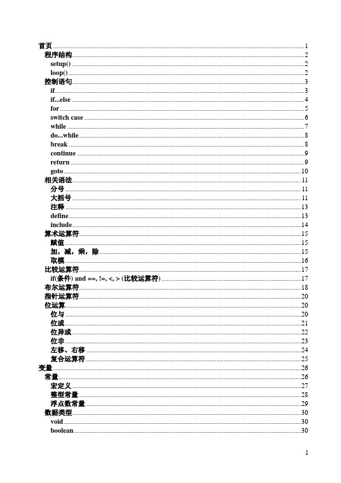
Implementing Quick Sort Algorithm (Contd.)
Truncate the last element, that is, pivot from List 1.
Smaller element 0
arr
1 55
2
3
4
5
6
7 30
28
46
38
16 89
83
Pivot Greater Value Smaller Value
Ver. 1.0
Session 5
Data Structures and Algorithms
Implementing Quick Sort Algorithm (Contd.)
Session 5
Data Structures and Algorithms
Implementing Quick Sort Algorithm (Contd.)
List is now partitioned into two sublists. List 1 contains all values less than or equal to the pivot. List 2 contains all the values greater than the pivot.
Ver. 1.0
Session 5
Data Structures and Algorithms