奥拓尼克斯PS17-5DN(8DN)
奥托尼克斯接近开关PRL18

奥托尼克斯接近开关PRL18
1. 简介
奥托尼克斯接近开关PRL18属于接近开关的一种,用于实现对物体的测量或检测,根据不同的物理量可以分为压力、重量、位置等不同类型的接近开关。
本文将主要介绍奥托尼克斯接近开关PRL18的相关信息。
2. 奥托尼克斯接近开关PRL18的特点
奥托尼克斯接近开关PRL18主要具有以下特点:
2.1 尺寸
奥托尼克斯接近开关PRL18的尺寸为18mm,相对于其他型号的接近开关具有较小的尺寸优势。
2.2 检测距离
奥托尼克斯接近开关PRL18的检测距离为8mm,可以检测较小物件的位置和运动。
2.3 工作方式
奥托尼克斯接近开关PRL18采用磁吸方式进行工作,检测过程不会对被测物体产生影响。
2.4 电气特性
奥托尼克斯接近开关PRL18的电气特性如下:
•工作电压:10-30V DC
•感应电流:200mA
•输出形式:2线式PNP输出
3. 安装方法
奥托尼克斯接近开关PRL18的安装方法如下:
•将接近开关安装到被测物体所在的位置,并确保与被测物体的距离适当。
•连接电源和输出信号线。
•调整被测物体的位置,直到接近开关的输出信号发生变化。
4. 应用场景
奥托尼克斯接近开关PRL18主要应用于以下场景:
•电子设备制造
•机械加工
•物料运输
5. 结论
综上所述,奥托尼克斯接近开关PRL18具有体积小、检测距离短、工作方式简单等特点,适用于多种场景,可提高生产效率和减少检测成本。
韩国奥托尼克斯传感器怎么样

传感器是工业4.0时代的重要角色,随着物联网在工业领域的应用推广,越来越多的设备需要采用传感器采集数据,进一步去挖掘数据的价值,通过数据分析提升设备效率,预测一些可能发生的事情,减少停机损失,让工厂更贴近市场需求。
奥托尼克斯的传感器是比较不错的,为什么这样说呢,本文就以光电传感器为例子:光电传感器检测距离广泛,从5mm至30m不等,用户可根据实际需要,选择合适的检测距离。
可远可近,可盐可甜!晶体管(NPN或PNP)输出的光电传感器,大部分响应时间为1ms以下,继电器输出的产品,响应时间为20ms 以下。
常规型光电传感器通常由发光器发射红色光(肉眼可见)或红外线光束(不可见),1束光,单通道,圆形扩散。
常规的产品,简单的功能,是无法满足广大用户日益增长的技术需求滴!奥托尼克斯为了实现使命:“创造更美好,更便捷的世界”,不断地在光电类产品的广度和深度上苦下功夫,创新产品和技术。
▼为了适应汽车和机床等油性环境行业,研发了耐油型的光电传感器,有效防止油污渗透。
▼为了优化印刷电路板(PCB)的检测,采用30mm x 3 mm矩形光束,不再受PCB板上的孔,凹槽,不完整加工或突出部分的影响。
▼当1道光束不能满足要求时,就用4道。
4个通道,光束独立,由点及面。
▼为了突破光电传感器检测精度及响应速度的极限,产品阵容同时包括数字显示型的光纤放大器。
因此奥托尼克斯的传感器是比较不错的。
河南科威腾电气设备有限公司自2007年公司成立以来销售业绩连年翻翻,在河南工控行业创下良好口碑。
我公司在伺服电机运动控制、飞剪、全自动系统生产线以及传感器应用等领域有丰富的经验。
我公司的优势是产品的销售与整个项目系统的开发相结合,能为客户优化系统配制,节约更多的资金和时间,使沟通更方便,服务更周到,及时,周到。
奥拓尼克斯PSN17-8DN2
奥拓尼克斯PSN17-8DN2
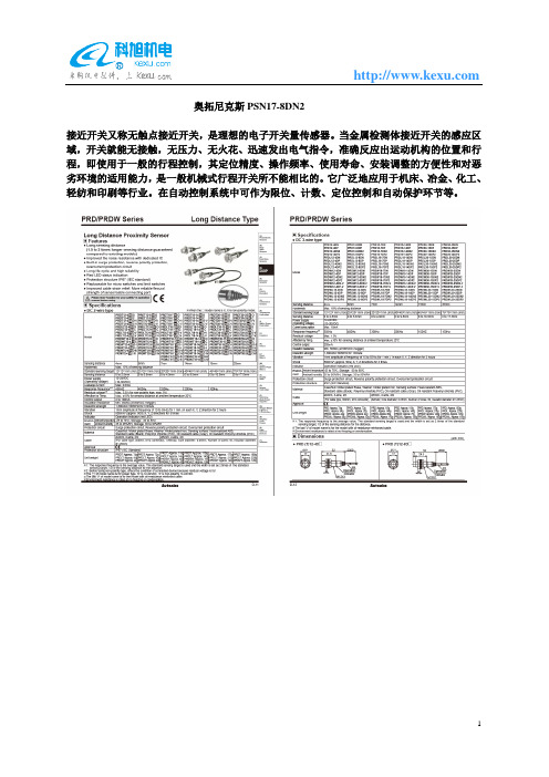
接近开关又称无触点接近开关,是理想的电子开关量传感器。
当金属检测体接近开关的感应区域,开关就能无接触,无压力、无火花、迅速发出电气指令,准确反应出运动机构的位置和行程,即使用于一般的行程控制,其定位精度、操作频率、使用寿命、安装调整的方便性和对恶劣环境的适用能力,是一般机械式行程开关所不能相比的。
它广泛地应用于机床、冶金、化工、轻纺和印刷等行业。
在自动控制系统中可作为限位、计数、定位控制和自动保护环节等。
SCHUNK产品的装配和操作手册-旋转活动器类型RM1说明书

Rotary actuator type RMDear Customer,Congratulations on choosing a SCHUNK product. By choosing SCHUNK, you have opted for the highest precision, top quality and best service.You are going to increase the process reliability of your production and achieve best machining results – to the customer's complete satisfaction.SCHUNK products are inspiring.Our detailed assembly and operation manual will support you.Do you have further questions? You may contact us at any time – even after purchase. You can reach us directly at the mentioned addresses in the last chapter of these instructions.Kindest Regards,Your SCHUNK GmbH & Co. KGPrecision Workholding SystemsBahnhofstr. 106 - 134D-74348 Lauffen/ NeckarTel. +49-7133-103-2503Fax +49-7133-103-2189 ********************.com Document last update: 18.02.2008R OTARY ACTUATORTYPES RM 12 TORM 21Rotary actuator type RMContents1SAFETY (2)1.1S YMBOL KEY (2)1.2A PPROPRIATE U SE (3)1.3S AFETY N OTES (4)1.4I NDICATIONS TO THE OPERATING MANUAL (4)2WARRANTY (5)3SCOPE OF DELIVERY (5)4TECHNICAL DATA (5)5OPERATING AND ENVIRONMENTAL CONDITIONS (5)6ASSEMBLY AND INSTALLATION (6)6.1D ESIGN PRECAUTIONS (6)6.2C OMPRESSED AIR SUPPLY (6)6.3S PECIAL CONNECTING MEASURES (6)6.4A SSEMBLY MEASURES (7)6.5M EASURES FOR THE INITIAL OPERATION (7)7HANDLING (8)7.1F INE ADJUSTMENT OF ROTATION ANGLE (8)7.2D AMPING ADJUSTMENT (8)7.3E ND POSITION INTERROGATION (9)7.4I NTERMEDIATE STOPS RZ (10)7.4.1Setting of intermediate position (10)7.4.2Damping adjustment (10)7.4.3Interrogation of intermediate position (10)8REPAIRS (11)9RESPONSE TO MALFUNCTIONS (11)10MAINTENANCE AND CARE (12)11REPLACEMENT PARTS (13)12INDEX .......................................................................... FEHLER! TEXTMARKE NICHT DEFINIERT. 13EC DECLARATION OF INCORPORATION . (14)14CONTACT (15)1 Safety1.1 Symbol keyYou will find this symbol wherever hazards for persons or damage to the productare possible.1.2 Appropriate UseThe rotary actuators are manufactured in accordance with the current level of technology and with recognised safety regulations. During their use, however, there may occur risks to life and limb of the user or impairment of the rotary actuator and other material assets.The rotary actuators are intended exclusively for the swivelling movement of service loads in any position that do not react in their manipulation with any risk to persons, property or the environment.The maximum permissible service loads and forces are given in our standard catalogue.Any usage beyond these definitions is inappropriate.The manufacturer cannot be held liable for loss or damage arising therefrom. The risk is borne exclusively by the user.Usage in accordance with directions includes observation of the user manual as well as adherence to the maintenance and repair specifications prescribed by the manufacturer.The rotary actuator must only be operated by persons that are familiar therewith and that have been instructed in the associated hazards. The relevant accident prevention regulations and the other generally recognised safety and occupational health regulations must be compliedwith.Rotary actuator type RM1.3 Safety Notes1. Responsibility for the compatibility of pneumatic equipment lies with the personwho designs the pneumatic system or takes the decision on its specifications.- Since the products specified herein can be used under various operatingconditions, their compatibility with the appropriate pneumatic system mustbe based on specifications and/or tests in order to conform to theirrequirements.2.Machines and equipment operated by pneumatic means may only be used by trained personnel.- Compressed air can be hazardous if an operator is not familiar with its use. The assembly, handling or repair of pneumatic systems is to be undertakenby trained and experienced personnel.3.Do not carry out maintenance work on machines and equipment and do not at-tempt to remove components until it has been confirmed that it is safe to do so.- Inspection and maintenance of machines and equipment may only be carried out after it has been confirmed that the devices that must be swit-ched off are in a securely deactivated condition. - If machine parts must be removed, carry out safety precautions as mentioned above. Deactivate the compressed air supply to this machine and release any remaining compressed air from the system.- Before machines and equipment are switched on again, take measures toensure that cylinder rods etc. are not pushed outwards. Allow compressedair to enter the system slowly so that counterpressure builds up gradually.4. Contact SCHUNK (see chapter 12 page 14) if the product is to be used under oneof the following conditions:- Conditions and environments that lie outside the stated specifications, orwhere the product is to be used outdoors.- Installation in equipment in conjunction with nuclear power, railways, aero-space, vehicles, medical equipment, food and drink, leisure equipment,emergency shutdown circuits, applications in presses or safety equipment.- Any application that may possibly have negative influences on persons,animals or property and that requires a special safety analysis.5. This user manual should always be easily accessible1.4 Indications to the operating manualThis user manual describes gripper actuators of series RM 12, RM 15 and RM 21.All statements in this user manual refer to the types stated above.Rotary actuator type RM2 WarrantyThe warranty period is 24 months or 40 million load cycles after delivery date from the factory, assuming use in single-shift operation and that the recommended maintenance and lubrication intervals are respected. Components that come into contact with workpieces, wearing parts, shock absorbers, stop screws and proximity switches are never included in the warranty.The warranty covers the replacement or repair of defective parts in the manufacturing plant. Further claims are hereby excluded. In this context, please also see our General Terms and Conditions.3 Scope of DeliveryThe scope of delivery comprises:- Rotary actuator type RM, depending on the version ordered4 Technical DataPlease consult our catalogue for further technical details. The last version is valid in each case. (in accordance with Chapter 2.3 General Terms and Conditions)The airborne sound emitted from the unit is <= 70dB(A)5 Operating and environmental conditions- Do not use the product in environments comprising corrosive gases, salt water, water or vapours.- For use in an atmosphere where water drops, oil, sprays etc, occur take appropriate countermeasures in order to ensure protection.- If electronic end switches are to be used, these should not be used in the presence of strong magnetic fields. Please contact SCHUNK (see chapter 12 page 14) if theproduct is to be used in the presence of strong magnetic fields.- Do not use the rotary actuator in an atmosphere in which it could come into contact with fluids such as oil or water.- Do not use the rotary actuator in an atmosphere in which it could come into direct contact with substances such as powder dust, dust, sprays etc.- Do not use the rotary actuator in an atmosphere in which sources of heat are present.- Do not subject the rotary actuator to excessive vibrations and/or shocks.Rotary actuator type RM6 Assembly and Installation6.1 Design precautions- A protective guard is recommended in order to minimise the risk of injury.- Ensure that loose, fixed and/or connected parts or tightened securely.- Operation without the shock absorbers included as standard in the scope of delivery is not permissible.- Take account of the possibility that the operating pressure may decrease as a result of power failures etc.- Pay attention to the possibility of the failure of power supplies.- Mount the compressed air supply in such a way as to prevent a gripping action.- Pay attention to emergency shutdown facilities.- Pay attention to what will happen after an emergency stop or abnormal stoppage.Ensure that nobody can be placed at risk or be injured when equipment is restarted.6.2 Compressed air supply- Use clean compressed air and insert a filter between the supply and the pneumatic system.- Install a water separator in the pneumatic system.- Use the product only within the range specified for the medium temperature and ambient temperature.Air specification- dry (free from condensation)- filtered to 10 microns- oiled or oil-free6.3 Special connecting measures- Use connecting pipes of a cross-section that is larger than or identical to that of the connector thread.- Blow air through the connecting pipes before fitting the devices in order to remove any dust, contaminant or particles.- Avoid the ingress of sealing material into the pipe network.- Do not remove pneumatic components from their packaging until shortly before fit-ting.Rotary actuator type RM6.4 Assembly measures- During the mounting of loads, do not allow the system to be subjected to impermissible forces or moments.- The flatness of the mounting surfaces must be less than 0.02mm.- Select the correct means of connection with a load that has its own guidance mechanism and ensure that this is adequately aligned.- Avoid contact with the rotary actuator during operation.- Select a suitable screw tightening torque for mounting of the rotary actuator or loads on the rotary actuator in accordance with the generally valid guidelines for screwconnections.6.5 Measures for the initial operationPlease read this user manual carefully. Knowledge of this user manual is essential in order to prevent errors and ensure problem-free operation.Under no circumstances may rotary actuators be operated with oiled air if theyare subsequently to be operated with oil-free air.- Check the technical specifications.- Do not use the device until you have checked that it functions correctly taking account of all permissible operating parameters.- Regulate the operating speed of the cylinder by means of throttle type non-return valves. Increase from the low speed to higher speeds until the required operatingspeed is reached.Selection and dimensioning- Do not subject the units to loads that exceed the limits of their operating range. If excessive loads are applied , the gripper jaw guidance system and closingmechanism could suffer damage or inaccuracies. The maximum permissible loadsare given in our standard catalogue.- Do not allow the system to experience impermissible forces or shocks.Rotary actuator type RM7 Handling7.1 Fine adjustment of rotation angleFor fine adjustment of the rotation angle and matching of the end damping to the mass moment of inertia occurring in operation, the following parts are included in the scope of delivery of each rotary actuator.- Stop collar (Pos. 10)- Locknut (Pos. 11)- Locknut (Pos. 12)- Shock absorber (Pos. 18)Once the locknut (Pos. 11) has been loosened, the rotation angle can be steplessly adjusted between 0 and 180 degrees by turning the stop collar (Pos. 10) with the integral shock absorber (Pos. 18). Each end position can be adjusted by 90 degrees.Figure 1: Fine adjustment of rotation angle7.2 Damping adjustmentOperation without the shock absorbers included as standard in the scope of delivery is not permissible.Please note the maximum permissible mass moment of inertia stated in our standardcatalogue.After the locknut (Pos. 12) has been loosened, the stroke length of the shock absorber and thus the damping curve can be matched to the mass moment of inertia occurring in operation by rotating the shock absorber (Pos. 18) inwards or outwards. This does not affect the rotation angle set previously.Rotary actuator type RM7.3 End position interrogationStandardised interrogation sets for direct mounting are available for interrogation of end posi-tions.Proximity switch - complete RMNS-...The scope of delivery includes:- 1x retaining plate- 2x switching cam- 2x proximity switch- 2x connection cableFigure 2: position of proximity switchAfter the clamping screw has been loosened, the switching cam can be steplessly adjusted in a vee-shaped slot in the turntable. The specific end position interrogation can thus be precisely adjusted for each rotation angle set.proximity switch RMNZproximity switch RMNSRotary actuator type RM7.4 Intermediate stops RZ7.4.1 Setting of intermediate positionIntermediate stops are additional modules for rotary actuators and are available for all rotary actuator sizes of this series.Figure 3: Rotary actuator shown in intermediate position at 90°The intermediate position can be set at any point over the entire swivel range of the rotary ac-tuator. It must be noted that the toothed racks of rotary actuators are tensioned without back-lash where a controlled intermediate stop is used. For an intermediate position of 90 degrees or more, the stop cylinders must be changed over.The intermediate position is set by rotating the complete stop cylinders inwards or outwards. The locknut (Pos. 5) must first be loosened and must be tightened again afterwards.7.4.2 Damping adjustmentThe stroke of the shock absorber and thus the damping curve can be matched to the mass moment of inertia occurring in operation by inserting shims under the shock absorber (Pos. 9). The stop sleeve (Pos. 2) with theh shock absorber (Pos. 9) and piston (Pos. 3) must be dismantled first.7.4.3 Interrogation of intermediate positionFor interrogation of the intermediate position, the interrogation set RMNZ-... is available. This interrogation set is identical with the end position interrogation set RMNS-... but contains only one switching cam, proximity switch and connection cable and is mounted on the opposite side.RZ 12: DIN 433-3.2-ST (max. 2mm) RZ 15: DIN 433-3.2-ST (max. 2mm) RZ 21: DIN 126-5.5-ST (max. 5mm)Rotary actuator type RM8RepairsThe repair or elimination of defects on our products by the customer may only be carried out with our explicit written agreement. Any failure to adhere to this principle renders invalid our warranty and liability for any resulting warranty or secondary losses.Following receipt and examination, all linear actuators of series RM can be repaired by SCHUNK.9Response to malfunctionsMalfunctions that are caused by defective components may only be remedied by replacement of these components.Defective components may only be replaced by SCHUNK genuine replacement parts.10 Maintenance and Careare subsequently to be operated with oil-free air.- The integral cylinders are lubricated for life and do not require relubrication. Operati-on with oiled or oil-free compressed air is permissible without restrictions.- The bearing arrangements of the turntable and of the toothed rack pinion unit are already lubricated. It is not therefore necessary to lubricate these again before opera-tion. Lubrication or relubrication of the toothed rack pinion unit with rolling bearinggrease is recommended after approx. 4 million cycles.- All rotary actuators of series RM are maintenance-free. In order to achieve the maxi-mum operating life, this chapter and chapter 6.2 (at page 6) of this user manualshould be observed.- Apart from normal cleaning of machines, no further maintenance measures arenecessary.Rotary actuator type RM11 Replacement partsAs standardised wear part sets, seal sets are available. The scope of delivery includes all seals.Ordering numbers of seal sets:- RMDI 12 for rotary actuator RM 12- RMDI 15 for rotary actuator RM 15- RMDI 21 for rotary actuator RM 21In accordance with the section drawing below, all other wear parts and individual parts are available as single items.Ordering numbers are as indicated in the following example- Part No. 1 RM 15-01 (for rotary actuator RM 15)Figure 4: section drawing RMRotary actuator type RM12 EC declaration of incorporationIn terms of the EC Machinery Directive 2006/42/EC, annex II B Manufacturer/ distributorSCHUNK GmbH & Co. KG. Spann- und Greiftechnik Bahnhofstr. 106 – 13474348 Lauffen/Neckar, GermanyWe hereby declare that the following product:Product designation: Rotary modules pneumatic, swivel unit Type designation: RM 12…RM21 ID number:0313000 (0313015)meets the applicable basic requirements of the Directive Machinery (2006/42/EC).The incomplete machine may not be put into operation until conformity of the machine into which the incomplete machine is to be installed with the provisions of the Machinery Directive (2006/42/EC) is confirmed.Applied harmonized standards, especially:EN ISO 12100-1 Safety of machines - Basic concepts, general principles for design -- Part 1: Basic terminology, methodologyEN ISO 12100-2 Safety of machines - Basic concepts, general principles for design -- Part 2: Technical principlesThe manufacturer agrees to forward on demand the special technical documents for the incomplete machine to state offices.The special technical documents according to Annex VII, Part B, belonging to the incomplete machine have been created.Person responsible for documentation: Mr. Michael Eckert, Tel.: +49(0)7133/103-2204Location, date/signature:Lauffen, Germany, January 2011p.p.Title of the signatoryDirector for DevelopmentRotary actuator type RM13 ContactGERMANY – HEAD OFFICE SCHUNK GmbH & Co. KG Spann- und Greiftechnik Bahnhofstrasse 106 – 134 D-Lauffen/Neckar Tel. +49-7133-103-0 Fax +49-7133-103-2399 **************.com CANADASCHUNK Intec Corp. 190 Britannia Road East, Units 23-24Mississauga, ON L4Z 1W6 Tel. +1-905-712-2200 Fax +1-905-712-2210 **************.com DENMARKSCHUNK Intec A/S Storhaven 7 7100 VejleTel. +45-43601339 Fax +45-43601492 **************.com HUNGARYSCHUNK Intec Kft. Széchenyi út. 70. 3530 MiskolcTel. +36-46-50900-7 Fax +36-46-50900-6 **************.comAUSTRIASCHUNK Intec GmbH Holzbauernstr. 20 4050 TraunTel. +43-7229-65770-0 Fax +43-7229-65770-14 **************.com CHINASCHUNK GmbH & Co.KG ShanghaiRepresentative Office 777 Zhao Jia Bang Road Pine City Hotel, Room 923 Xuhui District Shanghai 200032Tel. +86-21-64433177 Fax +86-21-64431922 **************.com FRANCESCHUNK Intec SARL Parc d´Activités des Trois Noyers 15, Avenue James de RothschildFerrières-en-Brie77614 Marne-la-Vallée Cedex 3Tel. +33-1-64 66 38 24 Fax +33-1-64 66 38 23 **************.com INDIASCHUNK India Branch Office # 80 B, Yeswanthpur Industrial Suburbs, Bangalore 560 022 Tel. +91-80-41277361 Fax +91-80-41277363 **************.comBELGIUM, LUXEMBOURG SCHUNK Intec N.V./S.A. Bedrijvencentrum Regio Aalst Industrielaan 4, Zuid III 9320 Aalst-Erembodegem Tel. +32-53-853504 Fax +32-53-836022 **************.com CZECH REPUBLIC SCHUNK Intec s.r.o. Ernsta Macha 1 643 00 BrnoTel. +420-545 229 095 Fax +420-545 220 508 **************.com GREAT BRITAIN, IRELAND SCHUNK Intec Ltd.Cromwell Business Centre 10 Howard Way, Interchange ParkNewport Pagnell MK16 9QS Tel. +44-1908-611127 Fax +44-1908-615525 **************.com ITALYSCHUNK Intec S.r.l. Via Barozzo22075 Lurate Caccivio (CO) Tel. +39-031-4951311 Fax +39-031-4951301 **************.com Rotary actuator type RMJAPANSCHUNK Intec K.K. 45-28 3-Chome Sanno Ohta-Ku Tokyo 143-0023 Tel. +81-33-7743731 Fax +81-33-7766500********************.jp www.tbk-hand.co.jpPOLANDSCHUNK Intec Sp.z o.o. Stara Iwiczna,ul. Słoneczna 116 A 05-500 Piaseczno Tel. +48-22-7262500 Fax +48-22-7262525 **************.com SOUTH KOREASCHUNK Intec Korea Ltd. # 907 Joongang Induspia 2 Bldg.,144-5 Sangdaewon-dong Jungwon-gu, Seongnam-si Kyunggi-do, 462-722 Tel. +82-31-7376141 Fax +82-31-7376142 **************.com SWITZERLAND, LIECHTENSTEIN SCHUNK Intec AG Soodring 19 8134 Adliswil 2Tel. +41-44-7102171 Fax +41-44-7102279 **************.comMEXICO, VENEZUELA SCHUNK Intec S.A. de C.V. Av. Luis Vega y Monroy # 332 Fracc. Plazas de Sol Santiago de Querétaro, Qro. 76099Tel. +52-442-223-6525 Fax +52-442-223-7665 **************.com PORTUGALSales Representative Victor MarquesTel. +34-937-556 020 Fax +34-937-908 692 Mobil +351-963-786 445 **************.com SPAINSCHUNK Intec S.L. Foneria, 2708304 Mataró (Barcelona) Tel. +34-937 556 020 Fax +34-937 908 692 **************.com TURKEYSCHUNK IntecBağlama Sistemleri veOtomasyon San. ve Tic. Ltd. Şti. Küçükyali Iş Merkezi Girne MahallesiIrmak Sodak, A Blok, No: 9 34852 Maltepe, Istanbul Tel. +90-216-366-2111 Fax +90-216-366-2277 **************.com NETHERLANDSSCHUNK Intec B.V. Speldenmakerstraat 3d 5232 BH ‘s -Hertogenbosch Tel. +31-73-6441779 Fax +31-73-6448025 **************.com SLOVAKIASCHUNK Intec s.r.o. Mostná 62 919 01 NitraTel. +421-37-3260610 Fax +421-37-6421906 **************.com SWEDENSCHUNK Intec AB Morabergsvägen 28 152 42 SödertäljeTel. +46-8 554 421 00 Fax +46-8 554 421 01 **************.com USASCHUNK Intec Inc. 211 Kitty Hawk Drive Morrisville, NC 27560 Tel. +1-919-572-2705 Fax +1-919-572-2818 **************.com 。
防水奥托尼克斯温控器说明书

防水奥托尼克斯温控器说明书
1、防水奥托尼克斯温控器是电子计量产品,其使用寿命为五年,每年需进行周期检验。
2、本防水奥托尼克斯温控器只能按照本公司规定的目的和方法使用。
未经授权的修改和使用非本公司所出售或推荐的零配件都有可能导致本系统出现故障,甚至损坏。
3、使用前请您详细阅读该说明书。
设计部门的工作人员请重点参阅性能指标、外形尺寸、机械安装及电气连接;安装人员请重点参阅外形尺寸、机械安装、电气连接及异常现象处理;使用人员请重点参阅基本操作及异常现象处理。
4、每台防水奥托尼克斯温控器在使用前应进行功能测试,以保证使用的可靠性及测量、控制的精度。
5、防水奥托尼克斯温控器在运输时应采用原包装,以免造成机械损坏。
6、防水奥托尼克斯温控器不使用时,请进行防潮处理。
7、防水奥托尼克斯温控器使用时应注意电源等级(无特殊说明时,一般为AC220V)。
8、当您准备使用防水奥托尼克斯温控器时,请仔细阅读该说明书的电气连接部分,确认连接无误后再给防水奥托尼克斯温控器送电!
9、为保证防水奥托尼克斯温控器输入信号质量,防水奥托尼克
斯温控器正常运行前务必拧紧传感器插头。
10、在干式变压器进行耐压测试前,必须将传感器插头与防水奥托尼克斯温控器分离,以避免防水奥托尼克斯温控器被损坏。
11、切勿用打火机等明火对传感器探头进行模拟温升试验,否则会损坏Pt100传感器。
12、避免在含有二氧化硫(SO2)或其他腐蚀性气体的环境中使用本防水奥托尼克斯温控器,否则会使继电器的触点失效。
机器人技术等级考试三级实操流程图程序汇真题与教材一致)

机器人技术等级考试三级实操流程图程序(汇真题与教材一致)一、实操流程图概述本文档描述了机器人技术等级考试三级实操的流程图程序。
该实操流程图程序与考试真题以及教材内容一致,能够帮助考生更好地理解和掌握机器人技术的相关知识和操作。
二、实操流程图程序下面是机器人技术等级考试三级实操的流程图程序:st=>start: 开始e=>end: 结束op1=>operation: 初始化机器人op2=>operation: 连接传感器与执行器op3=>operation: 启动机器人op4=>operation: 读取传感器数据op5=>operation: 检测障碍物op6=>operation: 控制执行器运动op7=>operation: 判断是否完成任务op8=>operation: 停止机器人op9=>operation: 输出成绩cond1=>condition: 是否连接成功?cond2=>condition: 是否检测到障碍物?cond3=>condition: 是否任务完成?st->op1->op2->op3->op4->op5->op6->op7->op8->cond3cond3(yes)->op9cond3(no)->op4op4->op5op5(yes)->op6op5(no)->op7op7(yes)->op8op7(no)->op4cond1(yes)->op4cond1(no)->econd2(yes)->op7cond2(no)->op6三、实操流程图程序说明1. 开始(Start)和结束(End)•开始节点(Start)标识了流程的开始。
•结束节点(End)表示流程的结束。
2. 初始化机器人(Initialize Robot)•初始化机器人(Initialize Robot)操作用于初始化机器人系统。
奥托尼克斯电容式接近开关

奥托尼克斯电容式接近开关奥托尼克斯电容式接近开关:助力智能交通和工业自动化进一步升级奥托尼克斯电容式接近开关是一种新型传感器,它的出现极大地推动了智能交通和工业自动化行业的发展。
那么,究竟这款产品有着哪些亮点呢?下面我们就来一一了解。
产品原理奥托尼克斯电容式接近开关,其工作原理是通过检测电容变化来检测靠近的物体。
在电容线圈和物体靠近时,电容值会随之变化,从而产生电容变化信号,即透过电路输出信号。
根据电容式接近开关不同的用途,采用的线圈和检测距离也有着不同。
产品亮点1. 长寿命:电容式接近开关使用的材料天然无污染,因此长久使用不会造成磨损和损坏。
2. 反应速度快:电容式接近开关的响应时间特别短,可以高效地监测物体的移动,并及时反馈。
3. 检测范围广:电容式接近开关检测的距离远,具有超强的侦测距离,便于远距离检测,准确度可靠。
4. 精度高:电容式接近开关可以检测物体的材质、性质、形状和大小,实现非接触式精准检测。
应用领域奥托尼克斯电容式接近开关的应用领域广泛,包括智能交通、机械制造、电力设备、自动化控制、医疗器械和航空航天等多个领域。
1. 智能交通:奥托尼克斯电容式接近开关可以感知车道内人车物,自动识别车型,并能够自动避让,大大提升交通安全性。
2. 机械制造:奥托尼克斯电容式接近开关可以感知物体的位置、大小和类型,实现自动化控制,提高生产效率和产量。
3. 电力设备:奥托尼克斯电容式接近开关可以检测高压缺陷,优化电力设备运行状态,提高电气设备的工作效率和安全性。
4. 自动化控制:奥托尼克斯电容式接近开关可以实现自动控制、调整、监测等多种功能,帮助企业降低成本、提高生产效率。
5. 医疗器械:奥托尼克斯电容式接近开关可以感知医疗器械和人体组织的距离和位置,实现非侵入性探测,提高手术和治疗的精度和安全性。
总结奥托尼克斯电容式接近开关,以其精准、快速、检测距离远、寿命长等优秀特性成为智能交通和工业自动化领域的重要装备,为推动行业升级换代和进一步提升高科技、高精度、高效率提供了强有力的支持。
17自由度人形机器人m

17自由度人形机器人
智能家居机器人价格,智能家居机器人厂家,家居机器人直销
17自由度人形机器人机体参数
身高:365mm;
重量:约1.65KG (含电池);kt02
关节:共17个关节;头:1个自由度,双臂6个自由度,双腿10个自由度;
装载全新机器人专用数字舵机及24路高端机器人控制器,附专用锂聚合物充电电池及充电器。
关于17自由度人形机器人支架结构
通体采用1mm厚度的硬铝合金精加工而成,部分支架做了加强边处理,使得支架不仅重量轻而且强度大。
每个关节之间都是由工程师仔细设计与测量,使得机器人腿部结构更加合理。
部分支架设计成为一体化结构,极大的方便了机器人的组装,节省了时间和体力。
关于17自由度人形机器人动力系统
采用双轴机器人数字舵机LD-2015,此款舵机扭力大,精度高,虚位小,零死区,使得机器人的动作更加敏捷,干净利落!
关于17自由度人形机器人控制器
采用高端24路双足机器人控制器,带有过载保护和低压报警,可以外接传感器。
软件配送,图形化编程,使得机器人的编程更加简单方便。
开关内置和模式开关内置的设计,将布线的烦恼降到最低!。
- 1、下载文档前请自行甄别文档内容的完整性,平台不提供额外的编辑、内容补充、找答案等附加服务。
- 2、"仅部分预览"的文档,不可在线预览部分如存在完整性等问题,可反馈申请退款(可完整预览的文档不适用该条件!)。
- 3、如文档侵犯您的权益,请联系客服反馈,我们会尽快为您处理(人工客服工作时间:9:00-18:30)。
奥拓尼克斯PS17-5DN(8DN)
接近开关又称无触点接近开关,是理想的电子开关量传感器。
当金属检测体接近开关的感应区域,开关就能无接触,无压力、无火花、迅速发出电气指令,准确反应出运动机构的位置和行程,即使用于一般的行程控制,其定位精度、操作频率、使用寿命、安装调整的方便性和对恶劣环境的适用能力,是一般机械式行程开关所不能相比的。
它广泛地应用于机床、冶金、化工、轻纺和印刷等行业。
在自动控制系统中可作为限位、计数、定位控制和自动保护环节等。