NTAG203F_SDS
浓盐水电子有限公司-太阳能转换器产品说明书

TPS_GCN_F_09.20E– Rev. 1 2012-10-29 Client: Huawei Technologies Co., LtdAdministration Building Headquarters of Huawei Technologies Co., Ltd.,Bantian, Longgang District, 518129 Shenzhen, PEOPLE'S REPUBLIC OFCHINAManufacturing place: Huawei Technologies Co., LtdAdministration Building Headquarters of Huawei Technologies Co., Ltd.,Bantian, Longgang District, 518129 Shenzhen, PEOPLE'S REPUBLIC OFCHINATest subject: Product: SOLAR INVERTERType:SUN2000-36KTL, SUN2000-33KTL-ATest specification: VDE-AR-N 4105:2011DIN VDE V 0124-100(VDE V 0124-100):2012DIN VDE 0126-1-1 (VDE V 0126-1-1):2013Purpose of examination: ∙Annex G.2, G.3, F3 and F4 from standard VDE-AR-N 4105∙TÜV SÜD certification mark specificationsTest result: The test results show that the presented product is in compliance with the specified requirements.Technical Report No. <70.409.16.086.03-02>G.2 Certificate of conformity for power generation unitsF.3 Requirements for the test report for power generation unitsG.3 Certificate of conformity of the network and system protectionF.4 Requirements for the test report for the NS protectionDated <2017-05-02>This technical report may only be quoted in full. Any use for advertising purposes must be granted in writing. This report is the result of a single examination of the object in question and is not generally applicable evaluation of the quality of other products in regular production.TPS_GCN_F_09.20E– Rev. 1 2012-10-29 1 Description of the test subject1.1 FunctionThese devices are transformer-less grid-connected PV inverters which converts direct current optimized by photovoltaic DC conditioner to alternating current, and they are in-tended to be connected in parallel with the public grid directly.They are intended for professional incorporation into PV system, and they are assessed on a component test basis.Firmware version: V200R0021.2 Consideration of the foreseeable misuseNot applicableCovered through the applied standardCovered by the following commentCovered by attached risk analysis1.3 Technical DataModel : SUN2000-36KTL, SUN2000-33KTL-APV input :d.c. Max. Input Voltage: 1100 Vd.c.d.c. MPP Range: 200-1000 Vd.c.d.c. Max. Input Current: 22 A /22 A /22 A /22 AIsc PV: 30 A /30 A /30 A /30 AAC output :a.c. Output Nominal Voltage: 3/N/PE~, 400Va.c. Nominal Operating Frequency: 50 Hza.c. Output Max. Current: 57,8 A (SUN2000-36KTL),48 A (SUN2000-33KTL-A)a.c. Output Rated Power: 36 kVA (SUN2000-36KTL),30 kVA (SUN2000-33KTL-A)a.c. Output Max. Active Power: 40 kW (SUN2000-36KTL), 33 kW (SUN2000-33KTL-A)a.c. Output Max. Apparent Power: 40 kVA (SUN2000-36KTL), 33 kVA (SUN2000-33KTL-A)Protection Class : IIngress protection : IP65Construction : Fixed equipmentSupply connection : Non-detachable power supply cableWeight : 55kg(SUN2000-36KTL)/60kg(SUN2000-33KTL-A)TPS_GCN_F_09.20E– Rev. 1 2012-10-29 2 Order2.1 Date of Purchase Order, Customer’s Reference2017.04.05, 7482130808/20002.2 Receipt of Test Sample, Location2016.04.15, 2017.04.15Nanjing CQC - Trusted Testing Technology Co., Ltd.No.99,Wenlan Road, Xianlin University Zone, Xianlin Street, Qixia District, NanJing, China2.3 Date of Testing2016-04-15 – 2016-05-04(original), 2017-04-15 – 2017-04-20(revised)2.4 Location of TestingNanjing CQC - Trusted Testing Technology Co., Ltd.No.99,Wenlan Road, Xianlin University Zone, Xianlin Street, Qixia District, NanJing, China2.5 Points of Non-compliance or Exceptions of the Test ProcedureNoneTPS_GCN_F_09.20E– Rev. 1 2012-10-29 3 Test Results3.1 Positive Test Results (as attachment of type D certificate)G.2 Certificate of conformity for power generation unitsCertificate of conformityPower generation unit No. 70.409.16.086.03-02ManufacturerHuawei Technologies Co., Ltd.Administration Building Headquarters of HuaweiTechnologies Co., Ltd., Bantian, Longgang District, 518129Shenzhen, PEOPLE'S REPUBLIC OF CHINA Type power generation unit SOLAR INVERTERModel SUN2000-36KTL, SUN2000-33KTL-AAssessment valuesMax. active power P Emax40048 W (SUN2000-36KTL)30322 W (SUN2000-33KTL-A)Max. apparent power S Emax40057 VA (SUN2000-36KTL)33127 VA (SUN2000-33KTL-A)Rated voltage 3/N/PE~, 400V Network connection rulesVDE-AR-N 4105 “Power generation systems connec tedto the low-voltage network”Technical minimum requirements for connection andparallel operation of power generation systems connectedto the low-voltage networkFirmware version V200R002Period of measurementFrom 2016-04-15 to 2016-05-04(original) and From 2017-04-15 to 2017-04-20(revised)The above mentioned power generation unit meets the requirements of VDE-AR-N 4105.Description of the structure and schematic set-up of the generating unit. (including single faultcheck)The generating unit integrated EMC filter on both PV and AC side converts direct current optimized byphotovoltaic DC conditioner to alternating current and it is intended to be connected in parallel with the low-voltage mains to supply common load. The generating unit has no electrical isolation between DC inputand AC output. The output is switched off by the failsafe inverter bridge and two relays in series. This al-lows a safe separation from generating unit to the network, also in case of failure. Refer to below illustra-tion.TPS_GCN_F_09.20E– Rev. 1 2012-10-29SUN2000-36KTL and SUN2000-33KTL-ATPS_GCN_F_09.20E– Rev. 1 2012-10-29 F.3 Requirements for the test report for power generation unitsExtract from test report for unit certificate“Determination of electrical properties”No. 70.409.16.086.03-02Type of systemGrid-connectedinverter for PVsystemManufacturer’s dataGeneration unitmanufacturerHuaweiTechnologies Co.,Ltd.Address:AdministrationBuildingHeadquarters ofHuaweiTechnologies Co.,Ltd., Bantian,Longgang District,518129 Shenzhen,PEOPLE'SREPUBLIC OFCHINAType of system:Grid-connected inverter for PVsystemActive power(nominal powerat referenceconditions):36kW (SUN2000-36KTL)30kW (SUN2000-33KTL-A)Rated voltage: 3/N/PE~, 400VPeriod ofmeasurement:From 2016-04-15 to 2016-05-04(original) and From 2017-04-15 to 2017-04-20(revised)Active power P Emax40048 W (SUN2000-36KTL), 30322 W (SUN2000-33KTL-A)(Assessment values)Reactive power reference(@0,91Un) – SUN2000-36KTLActive powerP/P Emax[%]10 20 30 40 50 60 70 80 90 100Max. possiblecosφunder-excited0,8020 0,8016 0,8014 0,8011 0,8009 0,8008 0,8007 0,8781* 0,9930* N/A**Max. possiblecosφover-excited0,7950 0,7975 0,7982 0,7987 0,7990 0,7991 0,7993 0,8695* 0,9880* N/A**The max. current is limited by software to 57,8 A, the apparent power and active power are limited accordingly when test at fixed grid voltage(0,91Un).S limited=P limited=57,8 x 209,3 x 3 ≈ 36293 W/VA“*”: Due to apparent power is limited to S limited, the active power is reduced accordingly when adjust cos φ. It is therefore not achieved to default cos φ at points 80% and 90% P/P Emax. The max. possible c os φ is recorded accordingly.“**”: The P Emax can not reached when test at 0,91Un.Reactive power reference (@Un) – SUN2000-36KTLActive powerP/P Emax[%]10 20 30 40 50 60 70 80 90 100Max. possiblecosφunder-excited0,8019 0,8015 0,8011 0,8010 0,8007 0,8007 0,8007 0,8006 0,9015* 0,9998*TPS_GCN_F_09.20E– Rev. 1 2012-10-29 Max. possiblecosφover-excited0,7951 0,7974 0,7982 0,7985 0,7991 0,7993 0,7993 0,7994 0,8988* 0,9998*“*”: Due to apparent power is limited to S Emax, the active power is reduced accordingly when adjust cos φ. It is therefore not achieved to default cos φ at points 90% and 100% P/P Emax. The max. possible cos φ is recorded accordingly.Reactive power reference (@1,09Un) – SUN2000-36KTLActive powerP/P Emax[%]10 20 30 40 50 60 70 80 90 100Max. possiblecosφunder-excited0,8023 0,8017 0,8012 0,8011 0,8008 0,8007 0,8007 0,8006 0,8966* 0,9998*Max. possiblecosφover-excited0,7954 0,7977 0,7984 0,7987 0,7990 0,7991 0,7994 0,7996 0,8987* 0,9998*“*”: Due to apparent power is limited to S Emax, the active power is red uced accordingly when adjust cos φ. It is therefore not achieved to default cos φ at points 90% and 100% P/P Emax. The max. possible cos φ is recorded accordingly.Reactive power reference (@Un) – SUN2000-33KTL-AActive powerP/P Emax [%]10 20 30 40 50 60 70 80 90 100Max. possiblecosφunder-excited- 0,8006 0,8010 0,8011 0,8012 0,8010 0,8010 0,8010 0,8012 0,9082*Max. possiblecosφover-excited- 0,7976 0,7977 0,7978 0,7980 0,7979 0,7973 0,7979 0,7982 0,9083*“*”: Due to apparent power is limited to S Emax, the active power is reduced accordingly when adjust cos φ. It is therefore not achieved to default cos φ at points 100% P/P Emax. The max. possible cos φ is recorded accordingly.Reactive power reference (@1,09Un) – SUN2000-33KTL-AActive powerP/P Emax[%]10 20 30 40 50 60 70 80 90 100Max. possiblecosφunder-excited- 0,8007 0,8010 0,8011 0,8012 0,8014 0,8011 0,8012 0,8008 0,9072*Max. possiblecosφover-excited- 0,7980 0,7977 0,7978 0,7980 0,7981 0,7981 0,7982 0,7981 0,9067*“*”: Due to apparent power is limited to S Emax, the active power is reduced accordingly when adjust cos φ. It is therefore not achieved to default cos φ at points 100% P/P Emax. The max. possible cos φ is recorded accordingly.TPS_GCN_F_09.20E– Rev. 1 2012-10-29 Compliance of required displacement factor cosφ– SUN2000-36KTLDefaultinsystemcontrol0,900ov 0,920ov0,940ov0,960ov0,980ov1,000 0,980un0,960un0,940un0,920un0,900unMeasuredvalueat PGUterminals0,8990 0,9198 0,9398 0,9598 0,9796 0,9998 0,9800 0,9600 0,9402 0,9202 0,9003Switching actions – SUN2000-36KTLMaking operation without default (of primary energy carrier) k i0,127Worst case at switch over of generator sections* k i-Making operation at reference conditions (of primary energycarrier)k i1,001Breaking operation at nominal power k i1,001Worst-case value of all switching operations k imax1,001Remark: “*” Not applicable for PV systemFlicker –SUN2000-36KTLAngle of network impedance ψk:32°1) 50°70°85°Coefficient of system flicker cψ: 2,38 - - -Remark: 1) R A = 0,24 Ω; X A = j 0,15 Ω at 50 Hz network impedance used for most unfavorable condition which is approximately 32° flicker angle.Reactive power transfer function – Standard-cosφ-(P)-characteristic – SUN2000-36KTLActive powerP/P n [%]10 20 30 40 50 60 70 80 90 100 cosφ0,9949 0,9987 0,9993 0,9995 0,9996 0,9799 0,9595 0,9398 0,9196 0,9999 Conform to Standard- cosφ-(P)-characteristicRemark:“*”:The maximum apparent power of the inverter is limited to SEmax. If setting cos φ≠1, the maximum active power is reduced accordingly. The active power 100% P/PEmax is therefore only achieved when cos φ = 1.Starting with a power of 0,2 P Emax, the characteristic curve shall be adhered to according to VDE AR-N 4105: 2011.TPS_GCN_F_09.20E– Rev. 1 2012-10-29 Harmonics – SUN2000-36KTLActivepowerP/Pn[%]0 10 20 30 40 50 60 70 80 90 100OrdinalnumberI [%] I [%] I [%] I [%] I [%] I [%] I [%] I [%] I [%] I [%] I [%]2 - 0,214 0,265 0,302 0,347 0,395 0,428 0,464 0,506 0,544 0,5633 - 0,103 0,102 0,082 0,070 0,065 0,061 0,069 0,080 0,095 0,1014 - 0,075 0,090 0,084 0,074 0,065 0,056 0,047 0,043 0,051 0,0525 - 0,149 0,177 0,274 0,312 0,367 0,374 0,407 0,394 0,409 0,3896 - 0,026 0,037 0,032 0,032 0,032 0,030 0,030 0,032 0,039 0,0717 - 0,291 0,237 0,215 0,171 0,196 0,199 0,271 0,302 0,350 0,3428 - 0,021 0,021 0,030 0,028 0,030 0,032 0,033 0,036 0,037 0,0579 - 0,035 0,044 0,048 0,051 0,050 0,055 0,057 0,072 0,072 0,08310 - 0,021 0,017 0,029 0,029 0,026 0,028 0,026 0,031 0,025 0,02011 - 0,216 0,192 0,333 0,329 0,350 0,340 0,351 0,384 0,378 0,38212 - 0,018 0,019 0,030 0,029 0,026 0,028 0,027 0,036 0,035 0,02913 - 0,250 0,167 0,285 0,306 0,307 0,348 0,341 0,392 0,398 0,40414 - 0,015 0,016 0,020 0,019 0,019 0,019 0,022 0,026 0,028 0,02715 - 0,039 0,036 0,032 0,033 0,036 0,036 0,034 0,033 0,037 0,03716 - 0,015 0,014 0,018 0,018 0,019 0,020 0,023 0,030 0,033 0,03417 - 0,115 0,145 0,181 0,199 0,209 0,220 0,256 0,277 0,289 0,31118 - 0,014 0,015 0,023 0,021 0,021 0,021 0,028 0,039 0,041 0,03619 - 0,086 0,136 0,158 0,161 0,178 0,186 0,207 0,245 0,255 0,26020 - 0,013 0,013 0,020 0,016 0,015 0,016 0,018 0,026 0,028 0,02421 - 0,023 0,024 0,039 0,032 0,022 0,026 0,024 0,030 0,032 0,03422 - 0,012 0,016 0,022 0,022 0,014 0,015 0,018 0,024 0,026 0,02523 - 0,069 0,096 0,125 0,115 0,125 0,139 0,160 0,176 0,207 0,22224 - 0,015 0,020 0,024 0,027 0,021 0,038 0,024 0,031 0,035 0,03525 - 0,045 0,076 0,114 0,097 0,109 0,118 0,135 0,148 0,175 0,19626 - 0,015 0,018 0,014 0,016 0,026 0,038 0,033 0,023 0,027 0,02827 - 0,018 0,021 0,017 0,020 0,037 0,033 0,034 0,022 0,027 0,02828 - 0,013 0,017 0,013 0,012 0,021 0,016 0,031 0,031 0,022 0,02229 - 0,017 0,049 0,082 0,062 0,083 0,084 0,104 0,110 0,132 0,15430 - 0,012 0,017 0,016 0,013 0,021 0,020 0,018 0,045 0,029 0,03131 - 0,021 0,044 0,070 0,048 0,068 0,072 0,080 0,081 0,114 0,13232 - 0,012 0,013 0,014 0,011 0,014 0,020 0,016 0,031 0,025 0,03433 - 0,018 0,014 0,013 0,016 0,014 0,021 0,018 0,019 0,031 0,03934 - 0,014 0,011 0,015 0,014 0,012 0,020 0,018 0,019 0,022 0,03335 - 0,026 0,026 0,043 0,038 0,053 0,061 0,062 0,053 0,079 0,10636 - 0,014 0,011 0,013 0,016 0,015 0,019 0,020 0,017 0,022 0,03637 - 0,025 0,015 0,033 0,034 0,041 0,055 0,051 0,040 0,068 0,09138 - 0,013 0,011 0,012 0,013 0,013 0,016 0,019 0,015 0,019 0,02739 - 0,018 0,016 0,016 0,016 0,015 0,018 0,023 0,022 0,023 0,02640 - 0,013 0,011 0,015 0,013 0,012 0,015 0,020 0,021 0,019 0,020TPS_GCN_F_09.20E– Rev. 1 2012-10-29 Subharmonics – SUN2000-36KTLActivepowerP/Pn[%]0 10 20 30 40 50 60 70 80 90 100Frequency[Hz]I [%] I [%] I [%] I [%] I [%] I [%] I [%] I [%] I [%] I [%] I [%]75 - 0,045 0,047 0,049 0,051 0,052 0,054 0,056 0,059 0,060 0,061125 - 0,035 0,036 0,035 0,038 0,036 0,036 0,036 0,037 0,036 0,035 175 - 0,030 0,029 0,028 0,029 0,029 0,028 0,028 0,030 0,029 0,027 225 - 0,027 0,025 0,025 0,026 0,026 0,027 0,027 0,030 0,027 0,026 275 - 0,025 0,024 0,024 0,025 0,025 0,025 0,026 0,028 0,026 0,025 325 - 0,024 0,023 0,023 0,024 0,024 0,025 0,025 0,027 0,026 0,025 375 - 0,023 0,022 0,023 0,023 0,024 0,025 0,025 0,027 0,026 0,025 425 - 0,023 0,022 0,022 0,023 0,024 0,025 0,025 0,027 0,026 0,024 475 - 0,022 0,021 0,022 0,022 0,023 0,024 0,024 0,026 0,026 0,024 525 - 0,022 0,020 0,021 0,022 0,022 0,023 0,024 0,027 0,026 0,024 575 - 0,021 0,019 0,020 0,021 0,022 0,023 0,024 0,026 0,026 0,024 625 - 0,021 0,019 0,020 0,020 0,022 0,023 0,024 0,025 0,027 0,025 675 - 0,020 0,018 0,019 0,020 0,022 0,023 0,024 0,025 0,027 0,025 725 - 0,022 0,022 0,022 0,024 0,025 0,027 0,028 0,030 0,031 0,028 775 - 0,020 0,020 0,021 0,022 0,024 0,025 0,026 0,027 0,030 0,029 825 - 0,021 0,021 0,021 0,022 0,024 0,026 0,028 0,030 0,032 0,028 875 - 0,017 0,016 0,017 0,018 0,019 0,021 0,023 0,024 0,029 0,026 925 - 0,016 0,016 0,017 0,018 0,019 0,021 0,023 0,024 0,030 0,025 975 - 0,016 0,016 0,019 0,018 0,019 0,021 0,023 0,024 0,030 0,026 1025 - 0,017 0,019 0,026 0,021 0,019 0,021 0,022 0,029 0,034 0,026 1075 - 0,016 0,022 0,036 0,039 0,018 0,020 0,022 0,027 0,028 0,026 1125 - 0,016 0,021 0,034 0,035 0,018 0,020 0,022 0,032 0,031 0,026 1175 - 0,018 0,022 0,041 0,049 0,022 0,024 0,024 0,027 0,025 0,027 1225 - 0,020 0,024 0,024 0,032 0,030 0,049 0,025 0,026 0,025 0,027 1275 - 0,021 0,022 0,023 0,028 0,036 0,036 0,045 0,023 0,025 0,027 1325 - 0,020 0,026 0,015 0,017 0,049 0,049 0,049 0,022 0,026 0,027 1375 - 0,017 0,026 0,015 0,016 0,034 0,031 0,063 0,025 0,025 0,028 1425 - 0,018 0,025 0,015 0,016 0,037 0,022 0,047 0,047 0,025 0,028 1475 - 0,017 0,024 0,014 0,015 0,022 0,023 0,043 0,046 0,025 0,027 1525 - 0,017 0,023 0,014 0,015 0,021 0,025 0,021 0,051 0,107 0,029 1575 - 0,018 0,019 0,014 0,015 0,021 0,028 0,022 0,044 0,028 0,043 1625 - 0,018 0,018 0,022 0,016 0,018 0,029 0,022 0,025 0,108 0,041 1675 - 0,021 0,015 0,015 0,018 0,017 0,028 0,024 0,022 0,026 0,053 1725 - 0,021 0,016 0,021 0,019 0,015 0,027 0,026 0,022 0,024 0,049 1775 - 0,020 0,016 0,014 0,021 0,015 0,021 0,027 0,022 0,024 0,046 1825 - 0,020 0,016 0,013 0,019 0,016 0,021 0,031 0,023 0,025 0,042 1875 - 0,021 0,016 0,013 0,019 0,017 0,023 0,028 0,022 0,024 0,037 1925 - 0,020 0,015 0,014 0,018 0,018 0,022 0,029 0,023 0,024 0,033 1975 - 0,020 0,016 0,016 0,017 0,019 0,023 0,030 0,025 0,024 0,029TPS_GCN_F_09.20E– Rev. 1 2012-10-29Higher frequencies – SUN2000-36KTLActivepowerP/Pn[%]0 10 20 30 40 50 60 70 80 90 100Frequency[kHz]I [%] I [%] I [%] I [%] I [%] I [%] I [%] I [%] I [%] I [%] I [%]2.1 - 0,064 0,043 0,056 0,058 0,063 0,079 0,089 0,095 0,092 0,1062.3 - 0,066 0,047 0,055 0,050 0,046 0,056 0,063 0,073 0,088 0,0742.5 - 0,070 0,047 0,055 0,047 0,044 0,054 0,059 0,062 0,072 0,0742.7 - 0,084 0,058 0,066 0,053 0,049 0,060 0,075 0,073 0,072 0,0832.9 - 0,067 0,041 0,047 0,041 0,037 0,046 0,050 0,053 0,065 0,0643.1 - 0,059 0,040 0,050 0,040 0,033 0,037 0,043 0,050 0,060 0,0503.3 - 0,052 0,037 0,050 0,040 0,032 0,035 0,043 0,050 0,055 0,0563.5 - 0,045 0,037 0,038 0,037 0,031 0,035 0,040 0,036 0,041 0,0523.7 - 0,041 0,037 0,038 0,035 0,029 0,035 0,034 0,033 0,043 0,0503.9 - 0,030 0,041 0,035 0,030 0,030 0,031 0,037 0,044 0,041 0,0424.1 - 0,029 0,035 0,033 0,031 0,031 0,038 0,040 0,029 0,031 0,0334.3 - 0,025 0,027 0,032 0,032 0,026 0,028 0,028 0,028 0,029 0,0294.5 - 0,025 0,027 0,028 0,027 0,025 0,027 0,027 0,026 0,028 0,0294.7 - 0,024 0,025 0,025 0,026 0,025 0,025 0,026 0,026 0,027 0,0274.9 - 0,024 0,025 0,025 0,026 0,025 0,025 0,025 0,025 0,026 0,0275.1 - 0,024 0,024 0,024 0,026 0,025 0,026 0,027 0,028 0,029 0,0305.3 - 0,024 0,024 0,024 0,025 0,024 0,025 0,025 0,025 0,026 0,0285.5 - 0,024 0,024 0,024 0,025 0,024 0,025 0,025 0,025 0,025 0,0255.7 - 0,024 0,024 0,024 0,025 0,025 0,026 0,026 0,026 0,027 0,0285.9 - 0,024 0,024 0,024 0,024 0,024 0,025 0,024 0,025 0,025 0,0256.1 - 0,024 0,024 0,024 0,024 0,025 0,025 0,025 0,025 0,025 0,0256.3 - 0,024 0,024 0,025 0,025 0,026 0,025 0,025 0,025 0,026 0,0266.5 - 0,024 0,024 0,025 0,025 0,026 0,025 0,026 0,026 0,026 0,0266.7 - 0,024 0,024 0,024 0,024 0,025 0,025 0,025 0,025 0,025 0,0256.9 - 0,024 0,024 0,024 0,024 0,025 0,025 0,025 0,024 0,025 0,0257.1 - 0,024 0,024 0,025 0,025 0,025 0,025 0,025 0,025 0,025 0,0257.3 - 0,024 0,024 0,025 0,025 0,025 0,025 0,025 0,025 0,025 0,0257.5 - 0,024 0,024 0,024 0,024 0,024 0,025 0,024 0,024 0,024 0,0247.7 - 0,024 0,024 0,024 0,024 0,024 0,025 0,024 0,024 0,024 0,0247.9 - 0,024 0,024 0,024 0,024 0,024 0,024 0,024 0,024 0,024 0,0248.1 - 0,024 0,024 0,024 0,024 0,024 0,025 0,024 0,024 0,024 0,0248.3 - 0,024 0,024 0,024 0,024 0,024 0,024 0,024 0,024 0,024 0,0248.5 - 0,024 0,024 0,024 0,024 0,024 0,024 0,024 0,024 0,024 0,0248.7 - 0,024 0,024 0,024 0,024 0,025 0,024 0,025 0,024 0,025 0,0258.9 - 0,024 0,024 0,024 0,024 0,025 0,024 0,025 0,025 0,025 0,025 Remark:The harmonic values are maximum values from all phases.TPS_GCN_F_09.20E– Rev. 1 2012-10-29 Harmonics – SUN2000-33KTL-AActivepowerP/Pn[%]0 10 20 30 40 50 60 70 80 90 100OrdinalnumberI [%] I [%] I [%] I [%] I [%] I [%] I [%] I [%] I [%] I [%] I [%]2 - 0,141 0,116 0,118 0,105 0,111 0,115 0,121 0,113 0,113 0,1373 - 0,183 0,193 0,227 0,207 0,193 0,195 0,188 0,196 0,203 0,2014 - 0,159 0,122 0,144 0,134 0,120 0,119 0,116 0,118 0,119 0,1225 - 0,789 0,973 0,563 0,435 0,418 0,471 0,502 0,553 0,593 0,6176 - 0,044 0,033 0,043 0,089 0,031 0,032 0,029 0,030 0,029 0,0317 - 0,409 0,903 0,805 0,713 0,548 0,439 0,351 0,314 0,297 0,3098 - 0,076 0,078 0,083 0,112 0,115 0,094 0,095 0,099 0,102 0,1419 - 0,051 0,056 0,084 0,092 0,102 0,099 0,063 0,062 0,059 0,08910 - 0,080 0,098 0,103 0,111 0,127 0,141 0,103 0,102 0,100 0,14111 - 0,428 0,219 0,111 0,381 0,512 0,569 0,593 0,594 0,618 0,61212 - 0,022 0,024 0,023 0,036 0,026 0,083 0,035 0,041 0,036 0,08913 - 0,308 0,223 0,106 0,270 0,402 0,465 0,510 0,522 0,553 0,55514 - 0,039 0,044 0,043 0,053 0,053 0,051 0,056 0,064 0,062 0,06515 - 0,031 0,041 0,036 0,047 0,047 0,046 0,051 0,054 0,054 0,05616 - 0,048 0,052 0,049 0,050 0,065 0,058 0,058 0,059 0,059 0,06917 - 0,149 0,156 0,130 0,104 0,246 0,334 0,379 0,403 0,417 0,42318 - 0,023 0,026 0,028 0,024 0,042 0,026 0,028 0,031 0,030 0,05219 - 0,137 0,117 0,158 0,169 0,200 0,311 0,394 0,462 0,512 0,55220 - 0,028 0,027 0,028 0,032 0,039 0,037 0,033 0,036 0,036 0,05521 - 0,039 0,038 0,044 0,036 0,035 0,058 0,051 0,053 0,050 0,05922 - 0,029 0,021 0,024 0,030 0,025 0,042 0,041 0,031 0,033 0,07923 - 0,100 0,054 0,078 0,080 0,072 0,141 0,185 0,209 0,230 0,23224 - 0,016 0,017 0,018 0,023 0,024 0,028 0,044 0,121 0,047 0,06725 - 0,074 0,086 0,078 0,195 0,149 0,181 0,257 0,323 0,379 0,41526 - 0,022 0,021 0,022 0,021 0,029 0,032 0,036 0,119 0,050 0,03927 - 0,034 0,035 0,037 0,034 0,030 0,041 0,052 0,073 0,072 0,05528 - 0,022 0,021 0,022 0,021 0,022 0,030 0,025 0,026 0,027 0,03429 - 0,124 0,124 0,088 0,048 0,051 0,061 0,101 0,137 0,162 0,17330 - 0,012 0,013 0,014 0,015 0,016 0,016 0,017 0,019 0,020 0,02231 - 0,116 0,150 0,135 0,126 0,142 0,111 0,140 0,194 0,240 0,27732 - 0,020 0,018 0,022 0,018 0,022 0,023 0,022 0,023 0,025 0,02733 - 0,030 0,031 0,029 0,030 0,025 0,030 0,034 0,037 0,037 0,04034 - 0,019 0,019 0,022 0,022 0,019 0,021 0,023 0,025 0,025 0,02735 - 0,080 0,072 0,067 0,038 0,055 0,036 0,058 0,096 0,133 0,16236 - 0,011 0,020 0,020 0,014 0,015 0,015 0,019 0,018 0,020 0,02237 - 0,130 0,105 0,111 0,094 0,138 0,119 0,106 0,134 0,170 0,20538 - 0,021 0,024 0,026 0,022 0,023 0,025 0,026 0,026 0,028 0,02939 - 0,026 0,025 0,028 0,024 0,030 0,029 0,026 0,029 0,030 0,03340 - 0,019 0,025 0,026 0,023 0,022 0,022 0,025 0,027 0,028 0,029TPS_GCN_F_09.20E– Rev. 1 2012-10-29 Subharmonics – SUN2000-33KTL-AActivepowerP/Pn[%]0 10 20 30 40 50 60 70 80 90 100Frequency[Hz]I [%] I [%] I [%] I [%] I [%] I [%] I [%] I [%] I [%] I [%] I [%]75 - 0,208 0,145 0,113 0,059 0,056 0,055 0,058 0,056 0,056 0,054125 - 0,067 0,226 0,146 0,048 0,047 0,046 0,045 0,046 0,045 0,044 175 - 0,191 0,126 0,117 0,079 0,046 0,046 0,045 0,046 0,045 0,045 225 - 0,093 0,069 0,115 0,095 0,054 0,054 0,054 0,055 0,053 0,054 275 - 0,071 0,048 0,084 0,135 0,047 0,049 0,047 0,049 0,047 0,048 325 - 0,073 0,041 0,063 0,123 0,082 0,042 0,043 0,043 0,041 0,045 375 - 0,050 0,043 0,064 0,105 0,109 0,046 0,050 0,054 0,051 0,120 425 - 0,047 0,045 0,058 0,096 0,172 0,069 0,050 0,051 0,050 0,139 475 - 0,044 0,041 0,054 0,057 0,110 0,124 0,046 0,047 0,047 0,152 525 - 0,036 0,034 0,037 0,060 0,124 0,141 0,113 0,048 0,064 0,222 575 - 0,037 0,040 0,041 0,064 0,044 0,125 0,184 0,293 0,235 0,102 625 - 0,036 0,039 0,040 0,067 0,042 0,121 0,117 0,057 0,071 0,221 675 - 0,035 0,036 0,037 0,067 0,040 0,041 0,179 0,289 0,230 0,050 725 - 0,029 0,033 0,033 0,050 0,051 0,036 0,038 0,045 0,043 0,043 775 - 0,031 0,032 0,033 0,051 0,048 0,037 0,038 0,042 0,041 0,057 825 - 0,028 0,029 0,030 0,031 0,064 0,035 0,039 0,040 0,041 0,061 875 - 0,025 0,056 0,043 0,030 0,061 0,034 0,039 0,042 0,042 0,075 925 - 0,038 0,030 0,038 0,031 0,058 0,047 0,036 0,038 0,038 0,078 975 - 0,033 0,055 0,046 0,031 0,046 0,048 0,036 0,037 0,037 0,075 1025 - 0,039 0,028 0,038 0,037 0,044 0,063 0,035 0,037 0,038 0,060 1075 - 0,031 0,025 0,031 0,037 0,027 0,076 0,031 0,032 0,033 0,068 1125 - 0,026 0,027 0,029 0,041 0,039 0,051 0,057 0,037 0,050 0,082 1175 - 0,022 0,025 0,026 0,033 0,037 0,059 0,088 0,046 0,106 0,068 1225 - 0,029 0,031 0,031 0,037 0,046 0,041 0,061 0,057 0,056 0,067 1275 - 0,027 0,029 0,031 0,030 0,041 0,048 0,088 0,052 0,108 0,064 1325 - 0,030 0,031 0,033 0,032 0,041 0,041 0,060 0,057 0,052 0,082 1375 - 0,024 0,026 0,029 0,028 0,031 0,044 0,034 0,038 0,039 0,058 1425 - 0,023 0,025 0,028 0,027 0,031 0,032 0,054 0,037 0,045 0,078 1475 - 0,019 0,021 0,021 0,022 0,024 0,025 0,027 0,031 0,032 0,034 1525 - 0,021 0,023 0,024 0,024 0,026 0,029 0,030 0,031 0,034 0,037 1575 - 0,018 0,019 0,021 0,020 0,023 0,025 0,026 0,028 0,030 0,032 1625 - 0,019 0,021 0,022 0,022 0,024 0,027 0,027 0,029 0,031 0,035 1675 - 0,018 0,020 0,021 0,021 0,022 0,026 0,026 0,027 0,028 0,036 1725 - 0,018 0,019 0,021 0,021 0,023 0,025 0,027 0,027 0,030 0,034 1775 - 0,017 0,027 0,022 0,022 0,023 0,024 0,029 0,028 0,032 0,036 1825 - 0,017 0,027 0,026 0,021 0,023 0,023 0,029 0,037 0,034 0,031 1875 - 0,023 0,026 0,026 0,023 0,025 0,025 0,029 0,029 0,033 0,034 1925 - 0,021 0,024 0,027 0,021 0,022 0,023 0,027 0,036 0,032 0,031 1975 - 0,025 0,021 0,028 0,024 0,025 0,027 0,028 0,030 0,032 0,035TPS_GCN_F_09.20E– Rev. 1 2012-10-29Higher frequencies – SUN2000-33KTL-AActivepowerP/Pn[%]0 10 20 30 40 50 60 70 80 90 100Frequency[kHz]I [%] I [%] I [%] I [%] I [%] I [%] I [%] I [%] I [%] I [%] I [%]2,1 - 0,125 0,183 0,148 0,150 0,168 0,164 0,147 0,167 0,204 0,240 2,3 - 0,106 0,120 0,125 0,121 0,131 0,130 0,116 0,121 0,137 0,155 2,5 - 0,067 0,090 0,116 0,135 0,147 0,175 0,169 0,164 0,168 0,174 2,7 - 0,101 0,124 0,125 0,146 0,166 0,199 0,197 0,179 0,177 0,197 2,9 - 0,079 0,068 0,085 0,109 0,136 0,158 0,185 0,182 0,170 0,153 3,1 - 0,059 0,067 0,071 0,064 0,066 0,073 0,091 0,107 0,115 0,120 3,3 - 0,064 0,083 0,082 0,101 0,111 0,123 0,143 0,167 0,174 0,168 3,5 - 0,051 0,070 0,079 0,074 0,084 0,097 0,107 0,129 0,150 0,161 3,7 - 0,046 0,070 0,075 0,075 0,071 0,070 0,073 0,076 0,077 0,086 3,9 - 0,043 0,054 0,059 0,066 0,079 0,079 0,084 0,093 0,114 0,133 4,1 - 0,039 0,045 0,050 0,049 0,054 0,057 0,062 0,066 0,071 0,088 4,3 - 0,037 0,039 0,041 0,042 0,048 0,049 0,048 0,049 0,057 0,068 4,5 - 0,036 0,041 0,044 0,039 0,044 0,048 0,050 0,051 0,050 0,054 4,7 - 0,034 0,035 0,036 0,035 0,038 0,039 0,041 0,044 0,044 0,045 4,9 - 0,034 0,036 0,037 0,035 0,036 0,038 0,038 0,040 0,040 0,040 5,1 - 0,034 0,036 0,037 0,035 0,035 0,036 0,037 0,040 0,041 0,041 5,3 - 0,033 0,034 0,034 0,034 0,033 0,035 0,034 0,035 0,036 0,036 5,5 - 0,033 0,034 0,034 0,034 0,034 0,035 0,034 0,035 0,036 0,037 5,7 - 0,033 0,033 0,034 0,035 0,036 0,035 0,034 0,035 0,036 0,036 5,9 - 0,033 0,033 0,033 0,033 0,033 0,033 0,033 0,033 0,034 0,034 6,1 - 0,032 0,033 0,033 0,033 0,033 0,034 0,033 0,033 0,034 0,034 6,3 - 0,033 0,033 0,033 0,033 0,033 0,034 0,034 0,034 0,035 0,035 6,5 - 0,033 0,034 0,035 0,035 0,035 0,035 0,036 0,035 0,036 0,036 6,7 - 0,032 0,032 0,032 0,032 0,033 0,034 0,034 0,033 0,033 0,034 6,9 - 0,032 0,032 0,032 0,032 0,033 0,033 0,033 0,033 0,033 0,033 7,1 - 0,033 0,033 0,033 0,033 0,033 0,034 0,034 0,034 0,034 0,034 7,3 - 0,033 0,033 0,033 0,033 0,033 0,033 0,033 0,034 0,033 0,033 7,5 - 0,032 0,032 0,032 0,032 0,032 0,033 0,033 0,033 0,033 0,033 7,7 - 0,032 0,032 0,032 0,032 0,032 0,032 0,033 0,033 0,033 0,033 7,9 - 0,032 0,032 0,032 0,032 0,033 0,033 0,033 0,033 0,033 0,032 8,1 - 0,032 0,032 0,032 0,032 0,032 0,032 0,033 0,033 0,033 0,033 8,3 - 0,032 0,032 0,032 0,032 0,032 0,032 0,033 0,032 0,033 0,032 8,5 - 0,032 0,032 0,032 0,032 0,032 0,032 0,033 0,032 0,033 0,032 8,7 - 0,032 0,032 0,033 0,032 0,032 0,032 0,033 0,033 0,033 0,033 8,9 - 0,032 0,032 0,032 0,032 0,032 0,032 0,033 0,033 0,033 0,033 Remark:The harmonic values are maximum values from all phases.。
模块检验项目
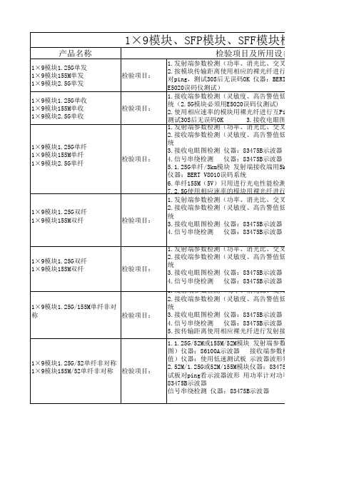
1×9模块1.25G/52单纤非对称 1×9模块155M/52单纤非对称 检验项目:
1.发射端参数检测(功率、消光比、交叉点、眼图)仪器:86100 2.接收端参数检测(灵敏度、高告警值低告警值)仪器:BERT V8 统 3.接收电眼图检测 仪器:83475B示波器 4.信号串绕检测 仪器:83475B示波器 5.按传输距离使用相应裸光纤进行发射接收视频传输 图象必须没 1.1.25G/52M或155M/52M模块 发射端参数检测(功率、消光比、交 图)仪器:86100A示波器 接收端参数检测(灵敏度、高告警值 值)仪器:使用低速测试板 示波器波形判定 2.52M/1.25G或52M/155M模块仪器:83475B示波器 发射参数检测( 试板对ping看示波器波形 用功率计对功率值 接收电眼图检测 仪 83475B示波器 信号串绕检测 仪器:83475B示波器
光比、交叉点、眼图)仪器:86100A示波器 高告警值低告警值)仪器:BERT V8010误码系 3.3V工作电 压
75B示波器 75B示波器 的核对) 接收端用5km裸光纤传输10S无误码丢包率OK
件检测:偏置电流、光功率、接收功率是否校
光比、交叉点、眼图)仪器:86100A示波器 高告警值低告警值)仪器:BERT V8010误码系
75B示波器 75B示波器 的核对) 光比、交叉点、眼图)仪器:86100A示波器 高告警值低告警值)仪器:BERT V8010误码系
3.3V工作电 压
75B示波器 75B示波器 的核对)
3.3V工作电 压
F模块检验项目
备注
及所用设备
光比、交叉点、眼图)仪器:86100A示波器 用于任何接 裸光纤进行互Ping,如25KM用30KM裸光纤进行 口类型、 仪器:BERT V8010误码系统(2.5G模块必须用 3.3V和5V模 块 高告警值低告警值)仪器:BERT V8010误码系 用于任何接 码仪测试) 口类型、 纤进行互Ping,如25KM用30KM裸光纤进行ping 3.3V和5V模 接收电眼图检测 仪器:83475B示波器 块 光比、交叉点、眼图)仪器:86100A示波器 高告警值低告警值)仪器:BERT V8010误码系 除单纤155M (5V)外用 75B示波器 于任何接口 75B示波器 接收端用5km裸光纤传输10S无误码丢包率OK 类型、3.3V 和5V模块 电性能检测、接收眼图检测、信号串绕检测 裸光纤进行互Ping必须用E5020误码仪测试 光比、交叉点、眼图)仪器:86100A示波器 高告警值低告警值)仪器:BERT V8010误码系 用于任何接 口类型、 75B示波器 3.3V和5V模 75B示波器 块
Mediatek_Wireless_Roadmap-2013-12-27

Confidential BMediaTek Roadmap UpdateDecember/27/2013Copyright © MediaTek Inc. All rights reserved.Confidential BAgenda▪ WiFi Market Update ▪ WiFi Networking Roadmap ▪ Beyond WiFiCopyright © MediaTek Inc. All rights reserved.2013/12/27-2-Confidential BWiFi Market UpdateCopyright © MediaTek Inc. All rights reserved.Smart Phone Say Hello to 802.11acConfidential BHTC New OneSamsung S4Sony Xperia Z Ultra C6802MediaTek13’Feb13’Mar13’Jun14’Q1Copyright © MediaTek Inc. All rights reserved.2013/12/27-4-11n vs. 11ac Transition100% 90% 80% 70% 60% 50% 40% 30% 20% 10% 0% 2013 2014 20152013/12/27 5Confidential BN300 takes entry level positionAC750/AC1200 replace N600 and get growth momentumAC-4SS (DBC) AC-3SS (DBC) AC-2SS (DBC) AC-2SS (FE, DBC) AC-1SS (DBC) 3SS (DBC) 2SS (DBC) 3SS 2SS 1SS20162017Copyright © MediaTek Inc. All rights reserved.Source: ABI, In-Stat, Mediatek IntelligenceMarket Dynamic▪ Router SKU Transition– – – – – –Confidential BN300 replaced N150 as 11n entry level router 11ac DBC router replaced 11n DBC router (AC1200 $79) LTE Smart Phone drive 11ac and NFC demand Normal power router + repeater to extend coverage Router 2.0 - Internet router (public cloud) + home router (personal cloud) Deep Packet Inspection (DPI) becomes mandatory function in mid-/high-end router▪ Next Generation Hotspot (Passpoint R2) moves Wi-Fi to the heart of the carrier network ▪ Home Security & Automation– – – – – Cloud & App, +touch panel for control Surveillance: WiFi Cloud IPC Security: BT Door Lock Home Automation: +Zigbee/Sub-1G for sensor network Healthcare: +BTLE2013/12/27 -6-Copyright © MediaTek Inc. All rights reserved.Confidential BWiFi Networking RoadmapCopyright © MediaTek Inc. All rights reserved.Confidential BAgenda▪ Chip Roadmap ▪ MT7620 Highlights ▪ MT7620 11ac Solutions ▪ MT7621 11ac Solutions ▪ MT7612 11ac SolutionsCopyright © MediaTek Inc. All rights reserved.2013/12/27-8-11n Router RoadmapN600(GbE) N750(GbE) N900(GbE)RT6856 RT3593 RT3593 MT7530 • MIPS34KEc (700 MHz) • DDRI/DDRII, NAND/SPI • FE SW, 802.3az • USB2.0 (2), rGMII, PCIe (2) • IPSec Engine (140Mbps) • AES256-CBC • Storage AcceleratorCPUMPConfidential BMT7620ART3593 MT7530MT7620ART5592 MT7530• MT7530 GbE SW • 5p+2 rGMII • 802.3az EEE • Jumbo FrameN600MT7620ART5592MT7620AMT7530N300MT7620AMT7620N• • • • • • • • • •2x2 802.11n (300 Mbps) MIPS24KEc (580/600 MHz) SDR/DDRI/DDRII, NAND/SPI/SD-XC/eMMC FE SW, 802.3az USB, rGMII(2), PCIe 2Gbps HWNAT (IPv6) Storage Accelerator Lowest Power Consumption Best IOT w/ Intel6300 eCos IPv6 logo ready turnkey (2/8)MT762x• • • • • • • • • •2x2 802.11n (300 Mbps) MIPS24KEc (580 MHz) DDRI/DDRII, SPI/SD-XC/eMMC FE SW, 802.3az USB, PCIe AES128/256-CBC Calibration Free 5V/0.6A power adapter DRAM embedded ULC rBOM, PCBN300GMPQ1’14Q2’14Q3’14Q4’14Q1’15Q2’1511ac Router Roadmap• MIPS1004K dual-core (880MHz) • 256KB L2 • DDRII/DDRIII, NAND/SPI/SD-XC • GbE SW, 802.3az EEE • USB 3.0, USB 2.0, rGMII, PCIe (3) • IPSec Engine (> 400Mbps) • HWNAT(IPv6)+BW Control • Storage Accelerator • NFC: MT6605 • SATAIII(2): 3rd PCIeCPUMPConfidential BAC1750(GbE)MT7621AMT7605E MT7615EAC1200(GbE)MT7621AMT7612E MT7602EMT7602E • LDPC, Beamforming • 256QAMMT7621AMT7612E MT7603EAC1200MT7603E • ULC • MCC • Airtime Fairness • 802.11v, 802.11j • Samples: Q1 2014• 4x4/4SS, 11ac stage2 • LDPC, Beamforming, MU-MIMO • 802.11v, 802.11j • CPU offload • Samples: Q4 2014MT7620AMT7612E• iPA • LDPC, Beamforming • Calibration FreeAC750MT7620AMT7610E• BeamformeeMPQ1’14Q2’14Q3’14Q4’14Q1’15Q2’15Dongle RoadmapAC1300CPUMPConfidential BAC866MT7612U • USB 3.0 • LDPC, Beamforming • Calibration Free, iPAMT7662U • USB 3.0 • BT 4.0+HS, LDPC, Beamforming • Calibration Free, iPA • Linux, Android MT7650U • USB 2.0 • BT 4.0+HS • Beamformee • Linux, AndroidAC433MT7610U • USB 2.0 • BeamformeeN450RT3573N300RT5572 RT5372 • USB 2.0 • Calibration Free, SoftAP mode • QFN40-5x5 (Smallest) MT7670U • USB 2.0 • High Power MT7603U • USB 2.0 • Calibration Free • ULCN150MT7601U RT3070MPQ1’14Q2’14Q3’14Q4’14Q1’15Q2’15PCIe Roadmap>AC1300CPUMPConfidential BMT7615E • 4x4/4SS, 11ac stage2 • LDPC, Beamforming, MU-MIMOAC866MT7612E • LDPC, Beamforming • Calibration Free, iPAAC433MT7610E • BeamformeeN450RT3593 • Calibration Free • LDPC, Beamforming • 256QAM • Calibration Free • 802.11j, 802.11v • 64QAMN300RT5592/EP RT5392MT7602E • USB 2.0 • Calibration Free, SoftAP mode • QFN40-5x5 (Smallest)MT7603EN150MT7601U RT3070MPQ1’14Q2’14Q3’14Q4’14Q1’15Q2’15MT7621 VPN Performance (>400Mbps)Confidential BVPN TunnelLAN:10.10.10.254Encrypti on DES 3DES AES-128 AES-192 AES-256 3DES AES-128 AES-192 AES-256 Authentication SHA-1 MD5 SHA-1 MD5 SHA-1 MD5 SHA-1 MD5 SHA-1 MD5 SHA-1 MD5 SHA-1 MD5 SHA-1 MD5 SHA-1 MD5 DH Group DH2 DH2 DH2 DH2 DH2 DH2 DH2 DH2 DH2 DH2 DH5 DH5 DH5 DH5 DH5 DH5 DH5 DH5NetScreen第一次 第二次 第三次503.963 415.579 450.942 552.657 597.048 546.626 507.185 588.509 422.110 380.032 457.272 455.986 444.925 332.600 448.310 422.465 423.996 505.989 507.322 504.105 421.491 549.283 399.405 395.676 382.091 510.567 398.124 381.551 540.925 508.904 360.313 562.598 420.892 473.680 420.030 472.003 510.725 476.088 517.963 512.740 380.029 502.125 454.674 420.783 557.360 478.124 421.747 552.370TCPTCPTCP平均449.617 465.0827 459.4313 509.5883 509.7547 523.999 474.851 498.975 394.7433 464.2413 436.69 419.44 514.4033 439.876 410.1233 512.4777Copyright © MediaTek Inc. All rights reserved.2013/12/27- 13 -MediaTek Technology RoadmapConfidential B20152014 {BBP} 1. BW 5/10 2. Airtime Fairness {MAC} 1. MCC 2. WiFi Positioning {SoC} KGD2013 {RF} DPD, 11ac iPA {BBP} LDPC, TxBF {MAC} STA-Proxy {SoC} HNAT+HQoS, VPN, Storage AcceleratorCopyright © MediaTek Inc. All rights reserved.{RF} 1. DPA 2. 4x4/4ss, 3. 11ac stage2 {BBP} 1. Smart Antenna v3 2. MU-MIMO2013/12/27- 14 -Software RoadmapReadyOpenWRT trunkOpenWRT (MT7620, 3.x)Confidential B2013 Q1 Q2 Q3 Q4 Q12014 Q2 Q3 Q42015 Q1 Q2●● OpenWRT(MT7620, 2.6.36)(RT5350, 3.x)● OpenWRT● OpenWRT(MT7621, 3.x)Linux SDK● SDK 4.1(MT7620, 2.6.36)● SDK 4.2(MT7621, 2.6.36)● SDK 5.0(Kernel 3.x)eCos OpenBSD● MT7620N/ ● MT7620NMT5350 SDK 2.4.1.4 (2/8M)● AC750 SDK2.4.3.0 (2/16M)● AC750 SDK2.4.5.0 (2/8M)eCos –IPv6 FreeBSD● MT7620N ● AC750 SDK3.0.3.0 (2/8M) - 15 2013/12/27IPv6 SDK 3.0.1.0 (2/16M)IPv6 SDK 3.0.2.0 (2/8M)● AC1200 SDK3.0.4.0 (2/8M)Copyright © MediaTek Inc. All rights reserved.Confidential BSDK 4.2 vs. 4.1 ComparisonSDK 4.1Kernel Chip 2.6.21 2.6.36 (RT6856, MT7620) RT3050, RT3052 RT3883, RT3662 RT3352, RT5350 RT6856, MT7620 GCC 3.4.2SDK 4.22.6.21 2.6.36 (RT6856, MT7620, MT7621) RT3050, RT3052 RT3883, RT3662 RT3352, RT5350 RT6856, MT7620 MT7621 GCC 4.6.3 (MT7621 default) (MT7620 option) uClibc 0.9.33.2 (MT7621 default) (MT7620 option) Fast path (MT7620, MT7621) Fast path (MT7620, MT7621) lighthttpd web server (BSD license) Linux 2.6.36 support 2.6.38 MT7620+MT7530 RT3883+MT7530 WM8960 YES (MT7621) 400Mbps (MT7621) YES xHCI (MT7621) Win8- 16 -DescriptionGccUser LibraryuClibc 0.9.28PPTP L2TP HTTP Server Layer7 QoS Openswan Gigabit Switch Audio DAC HQoS VPN SPDIF USB Windows certificationn/a n/a Go-ahead Linux 2.6.21 only 2.6.22 RT3883+Vitesse WM8750 n/a 150Mbps (RT6856) n/a EHCI (RT6856/MT7620) Vista/Win7MT720 performance gain ~120% MT7620 performance gain ~100% /QDMACopyright © MediaTek Inc. All rights reserved.2013/12/27Value Added SoftwareDPI +iQoS DPI +iQoS (Broadweb) CAPWAP user kernel driverConfidential BSamba, Airplay, Airprint, DLNA DMSVPN NTFS (Paragon) (MediaTek)NTFS (Paragon)Remote USBUSB Printer Audio StorageIPv6 HNAT HQoS (MediaTek)Storage Accelerator (MediaTek)VoW (MediaTek)Mesh (TerraNet)IP cam H.264 (AIT/Sonix) Audio DAC (WM8960)Copyright © MediaTek Inc. All rights reserved.2013/12/27- 17 -Confidential BAgendaChip Roadmap ▪ MT7620 Highlights ▪ MT7620 11ac Solutions ▪ MT7621 11ac Solutions ▪ MT7612 11ac SolutionsCopyright © MediaTek Inc. All rights reserved.2013/12/27- 18 -Confidential BMT7620A Functional Block3.3V 20/40MHz Crystal PMU 2.5/1.0V Clock/Timer/Reset/PLL DRAM Controller NAND/SD-XC/eMMC SPI RF FEM RF FEM MAC BBP UART Full+ UART Lite USB 2.0 Host/Device CTRL/PHY I2C PPE w/ IPv6 I2S PCM 2 3 4 External Interface TransformerSDRAM(512Mbits) DDR1(1Gbits) DDR2(2Gbits) NAND Flash(8Gbits) SPI Flash/Codec UART Interface USB 2.0 Interface EEPROM/Control Audio Interface Codec GPIO/LEDMIPS 24KEc (580/600 MHz) 64K I-Cache 32K D-Cache5G WiFi 2x2 11n: RT5592 2x2 11n: RT5592EP (HP) 3x3 11n: RT3593 1x1 11ac: MT7610ERGMIIPCIe Storage Accelerator Ethernet SwitchRGMII01Copyright © MediaTek Inc. All rights reserved.2013/12/27- 19 -MT7620 Highlights• Best DBC TP w/ Intel 6300 • Best TP w/ mutiSTAs • No. 1 HNAT in smallnetbuilder • First IPv6 HNATConfidential BBest DBC Throughput w/ Intel63002Gbps IPv6 HNATMT7620Lowest Power Consumption• Lowest power consumption • Thermal PK w/ E900USB 2.0 Samba Performance• Perform same performance w/ EA3500 and E4200v2Copyright © MediaTek Inc. All rights reserved.2013/12/27- 20 -HNAT (Chariot) Benchmarkipv6 HNATConfidential B2Gbps HNATOutperform in iPv6 benchmarkCopyright © MediaTek Inc. All rights reserved.2013/12/27- 21 -Confidential BPower Consumption BenchmarkD-LINK DIR-605L RTL8196C+ RTL8192CE 2.31 2.64 1.42 1.38 1.37MT7620NSDRTenda W308R BCM5357TP-LINK TL-WR841N AR9341Uplink Downlink STA associated STA unassociated Radio off1.80 2.18 1.03 0.83 0.613.42 4.41 2.88 2.79 2.072.632 3.290 2.444 2.350 2.068Copyright © MediaTek Inc. All rights reserved.2013/12/27- 22 -Confidential BDBC TP Benchmark (vs. Intel6300)Copyright © MediaTek Inc. All rights reserved.2013/12/27- 23 -Peak Throughput Benchmark APto1STA or APto2STAsConfidential BCopyright © MediaTek Inc. All rights reserved.2013/12/27- 24 -N300/600, AC750/1200(GbE) Solution▪ MT7620A (580MHz)– – – – – 2x2 11n 2.4GHz GbE LAN(4)+WAN USB 2.0, SD-XC, I2S DDR2, SPI Flash PCIe: 802.11 a/n/acMT7620AConfidential B1x1/2x2 11ac▪ MT7530– 5p GbE SwitchMT7530▪ 4L PCB, double sides▪ OS– Linux SDKCopyright © MediaTek Inc. All rights reserved.2013/12/27- 25 -Outdoor AP Solution (Industry Spec.)▪ MT7620A (580MHz)– – – – – 2x2 11n 2.4GHz GbE(2) USB 2.0, PoE DDR1, NAND Flash PCIe• •Confidential BrGMII iNIC802.11 a/n/ac 802.11ac iNICMT7620A– rGMIIPCIe 1x1/2x2 11ac▪ HW Spec.– 4L PCB, double sides – -40~85 degrees (Industry Spec.) – Tx PowerMCS0: 26.8dbm per chain • Over temperature: +- 1dbm•PoE▪ OS– Linux SDKCopyright © MediaTek Inc. All rights reserved. 2013/12/27 - 26 -Confidential BAgendaChip Roadmap MT7620 Highlights ▪ MT7620 11ac Solutions ▪ MT7621 11ac Solutions ▪ MT7612 11ac SolutionsCopyright © MediaTek Inc. All rights reserved.2013/12/27- 27 -AC750 Products▪ Chip: MT7620A+7610EConfidential B▪ MT7620A HNAT, DPD, STA-Proxy, USB performance outperform among all 2x2 11n SoC ▪ eCos IPv6 turnkey for small memory footprint ▪ Shipping AC750 modelsD-Link (DIR-810)Copyright © MediaTek Inc. All rights reserved.IO-Data (WN-AC733GR)2013/12/27 - 28 -PCI (MZK-750DHP)AC750 Solution▪ MT7620A (580MHz)– – – – 2x2 11n 2.4GHz FE LAN(4)+WAN USB 2.0, SD-XC, I2S DDR2, SPI FlashMT7620AConfidential BMT7610E▪ MT7610E– 1x1 11ac (ePA)▪ 4L PCB, double sides▪ Power Consumption– 3.13w (power optimized) – 3.96w (rBOM optimized)▪ OS– Linux SDK – eCos turnkey (2/16)Copyright © MediaTek Inc. All rights reserved. 2013/12/27 - 29 -AC750 vs. HTC New One TP140 120 100 80 60 40 20 0 UplinkCopyright © MediaTek Inc. All rights reserved.Confidential BMbps119.288.890.311ac TPDnlink2013/12/27 - 30 -Bi-directionAC1200(FE) Solution▪ Chip: MT7620A+7612EConfidential B▪ HNAT, DPD, STA-Proxy, USB performance outperform among all 2x2 11n SoC ▪ enable 11ac iPA w/ industry lowest rBOM ▪ support ePA for better coverage ▪ eCos IPv6 turnkey for small memory footprintCopyright © MediaTek Inc. All rights reserved.2013/12/27- 31 -AC1200 Solution▪ MT7620A (580MHz)– – – – 2x2 11n 2.4GHz FE LAN(4)+WAN USB 2.0, SD-XC, I2S DDR2, SPI FlashConfidential BMT7612E▪ MT7612E– 2x2 11ac (iPA/ePA)MT7620A▪ 4L PCB, double sides ▪ Power Consumption– 3.13w (power optimized) – 3.96w (rBOM optimized)▪ OS– Linux SDKCopyright © MediaTek Inc. All rights reserved.2013/12/27- 32 -Confidential BAC1200 iPA Benchmark▪ Tx Power BenchmarkTX output (dBm) MT7612EBelkin AC1000 RTL8197D+ RTL8192ER+ RTL8812AR5GRF HW OFDM HT20 HT40 VHT20 VHT40 VHT80 6M 54M MCS0 MCS7 MCS0 MCS7 MCS0 MCS8 MCS0 MCS9 MCS0 MCS92x2 ac iPA 19 16.5 19 15.5 18.5 15.5 19 15 18.5 15 17.5 152x2 ac ePA 16 14DIR-860 AC1200 (BCM) 2x2 ac ePA 18 16 18 16 18 161218 14Copyright © MediaTek Inc. All rights reserved.2013/12/27- 33 -*TX Pout is single chain data at antenna port which includes 1.5dB loss (transmission line+diplexer+IPEX connector)Confidential BAgendaChip Roadmap MT7620 Highlights MT7620 11ac Solutions ▪ MT7621 11ac Solutions ▪ MT7612 11ac SolutionsCopyright © MediaTek Inc. All rights reserved.2013/12/27- 34 -Confidential BMT7621A Function Block20/25/40MHz Crystal DRAM Controller Clock/Timer/Reset/PLL NAND/SD-XC/eMMC SPI (2)DDR2(2Gbits, 1066) DDR3(4Gbits, 1200) NAND Flash(8Gbits) SPI Flash/Codec UART Interface USB 3.0 Interface USB 2.0 Interface SATA SATAIII (2) Audio Interface NFC MT6605 GPIO/LED11n WiFiPCIeMIPS 1004KEc (880 MHz) 32K I-Cache 32K D-Cache L2-Cache 256KB Storage AcceleratorMIPS 1004KEc (880 MHz) 32K I-Cache 32K D-Cache Cache Coherency Port HNAT+ BW CTRLUART Lite (3) USB 3.0 Host11ac WiFiPCIeUSB 2.0 Host PCIe I2S, PCM, S/PDIFCryptoGigabit SwitchRGMII01234I2C External InterfaceTransformerCopyright © MediaTek Inc. All rights reserved.2013/12/27- 35 -MT7621 ApplicationConfidential BEthernet USB dongle SPDIFeMMC SDXC USB/SATAUSBUSB (printer)Airplay WiFi MT7662 BT Sink play I2C MT6605 PCM (VoIP)I2S I2SSPITouch panelCopyright © MediaTek Inc. All rights reserved. 2013/12/27 - 36 -MT7621N/AMT7621A Package GbE Power Consumption PCB Heat Sink Application TFBGA 11.7x13.6 GbE(5)+rGMII 2.4W 2/4L Yes AC1200G-Router MT7621N TFBGA 11.7x13.6 rGMII 1.2W 2/4L NoConfidential BAC1200-Repeater NAS+GbE(1) AC1200-FE Internet RouterCopyright © MediaTek Inc. All rights reserved.2013/12/27- 37 -Confidential BMT7621 Introduction▪ Platform based network processor for 2x2/3x3 11ac, LTE cat4/5 with rich extensions– Rich I/O sets: 5p GbE switch, rGMII, PCIe(3), USB3, USB2, SD-XC, I2S, PCM, S/PDIF▪ HNAT+BW CTRL can work seamlessly– HNAT w/ 2Gbps wired speed IPv6 routing – HW bandwidth control to replace software scheduler▪ Upgradable L7 QoS database for “Auto QoS” ▪ Storage accelerator – GSO/GRO, fast DMA for write offload ▪ >400 Mbps VPN crypto engine ▪ NFC for WPS replacement ▪ Industry lowest power consumption ▪ World’s first 2x2 11ac iPA to save rBOM ▪ World’s first 2x2 11ac DBC 2L design to save rBOMCopyright © MediaTek Inc. All rights reserved. 2013/12/27 - 38 -AC1200AC1200 -GbE 4L RFB▪ 4L, double side ▪ DDR3 1200/NAND Flash ▪ On board dual band concurrent WIFI– 7612E: 2x2 11ac iPA/iLNA – 7602E: 2x2 11n iPA/iLNAGbE 5p GbEConfidential BU3U2 MT6605 (NFC)IC+ GbE PhyNAND Flash MT7621 A DDR3 (1200)▪ Co-crystal design ▪ External high power module– 7612E: 2x2 11ac – 7602E: 2x2 11n (256QAM) – 7603E: 2x2 11n (64QAM)SD-XCSATA3.0ASM1061 MT7602E (2.4GHz) MT7612E (11ac) S/PDIF▪ USB 3.0/2.0/SATA3.0Copyright © MediaTek Inc. All rights reserved. 2013/12/27 - 39 -*Note: PCB cost estimation by vendor “Newheart”AC1200AC1200 -GbE 2L RFB▪ PCB cost down 40%– Dimension: 168mm x 115mm x 1.6mm – Single side – FR4 PCB: 100pcs estimation – 4Layer:NTD 175 – 2Layer: NTD 105*U 2Confidential B5p GbESD-XC DDR2 (1066)▪ DDR2 800/1066, SPI flash ▪ Co-crystal design ▪ On board dual band concurrent WIFI– 7612E: 2x2 11ac iPA/iLNA – 7602E: 2x2 11ac iPA/iLNAMT7602E (2.4GHz)MT7621ASPI FlashMT7612E (11ac)▪ USB 2.0 HS host supportCopyright © MediaTek Inc. All rights reserved. 2013/12/27 - 40 -MT7621A HDK V31*Note: PCB cost estimation by vendor “Newheart”Benchmark with Dlink DIRDIR-860LBetter computing power Integrated RF front-endConfidential BBenchmark Chip Set AC1200-GbE MT7621A+ MT7612E+MT7602E iPA/iLNA Dual Core 880MHz TX:iPA performance better than competitor ePADlink DIR-860L BCM47081A0+ BCM4352+BCM43217 ePA/eLNA Single Core 800MHz Front-end module:RFMD RFFM4501CPU WIFI 5GMTK AC1200-GbERX:Low rate worst than competitor eLNA 0.5dB High rate better than competitorBetter RF performanceWIFI 2.4GTX:iPA performance better than competitor iPATX:iPARX: Dlink DIR-860L Excellent power consumption Lower thermal risk Cost advantage Power Consumption Thermal r-BOMiLNA better than competitor iLNARX: iLNAUplink: 7.21W Downlink: 7.45W Less heat sink, thermal pad and shielding case USD: 3.8638 Co-clock supportUplink: 9.03W Downlink: 10.98W More thermal strategy USD: 6.5361 w/ RF front-end USD: 5.3967 w/o RF front-endNote: rBOM cost is not including thermal strategy, and shielding case Copyright © MediaTek Inc. All rights reserved. 2013/12/27 - 41 -Benchmark with Netgear R6200v2Confidential BBenchmark Chip Set AC1200-GbE MT7621A+ MT7612E+MT7602E ePA/eLNA Dual Core 880MHz TX:ePA: SKYWORKS SKY85402-11Netgear R6200v2 BCM47081A0+ BCM4352+BCM43217 ePA/eLNA Single Core 800MHz Front-end module:RFMD RFFM4501Better computing power Better RF performance MTK AC1200-GbECPU WIFI 5GRX:eLNASKYWORKS SKY85601-11Better RF performanceWIFI 2.4GFront-end module:RFMD RFFM4203TX:ePA: SKYWORKS SE2528RX: Netgear R6200-V2 Power Consumption Lower thermal risk Cost advantage Thermal r-BOM Less heat sink, thermal pad and shielding case USD:3.8638* Co-clock support USD: 3.9684*eLNA: Richwave RTC6602Uplink: 9.55W Downlink: 12.48W*Note: rBOM cost is not including external RF front-end, thermal strategy, and shielding case Copyright © MediaTek Inc. All rights reserved. 2013/12/27 - 42 -Media Security Gateway (MT7621+STB+ZigBee)Confidential B11n WiFiDDR3 NAND11ac WiFiUSB 2.0 USB 3.0STB SoC (Slave )ASM 1060ZigBeeMT7621 (Host)PCIeHDDSLICUART rGMII Transformer (1000Mps)R J 1 1R J 1 1R J 4 5R J 4 5R J 4 5R J 4 5MocaCopyright © MediaTek Inc. All rights reserved.2013/12/27- 43 -MT762xA + 2.8”(240x320 Dots) TFT +Touch Panel (Resistive (Resistive) )Confidential BCopyright © MediaTek Inc. All rights reserved.2013/12/27- 44 -What’s QoS?▪ End to End ▪ Big Pipe to Small Pie ▪ QoS Components1 Classifier 2 Queue/BW Mgmt 3 Scheduler/ShaperConfidential BCopyright © MediaTek Inc. All rights reserved.2013/12/27- 45 -HWHW-BWBW-CTRL - UpstreamConfidential B1 2 3 4 3 2 1Copyright © MediaTek Inc. All rights reserved.2013/12/27- 46 -HWHW-BWBW-CTRL - DnstreamConfidential B1 2 3 4 3 2 1Copyright © MediaTek Inc. All rights reserved.2013/12/27- 47 -HWHW-BWBW-CTRL – Dnstream (2)1Confidential B2Copyright © MediaTek Inc. All rights reserved.2013/12/27- 48 -USB 3.0 Samba BenchmarkConfidential BAP Linksys EA6400 Buffalo AC1750 D-Link DIR-860L MT7621AFormatHDD Model NameRead (MByte/sec) 13.75Write (MByte/sec) 11.67 15.77test tool InterfaceFAT32Buffalo HD-LB131.45 37.93 72.30IOMETER USB3.0 16.55 29.50Copyright © MediaTek Inc. All rights reserved.2013/12/27- 49 -Confidential BAgendaChip Roadmap MT7620 Highlights MT7620 11ac Solutions MT7621 11ac Solutions ▪ MT7612 11ac SolutionsCopyright © MediaTek Inc. All rights reserved.2013/12/27- 50 -。
PFSWITCH 2048T 商品说明书
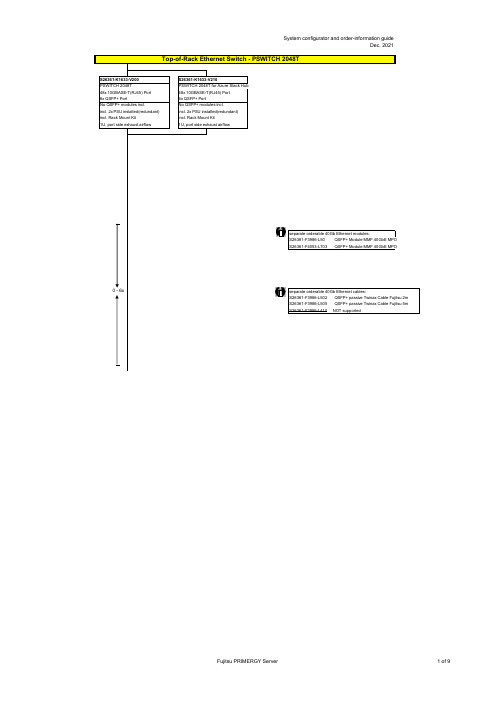
no power cord
T26139-Y3850-E10
T26139-Y1968-L180 T26139-Y1968-L250 T26139-Y1968-L10
T26139-Y1741-L90
T26139-Y1757-L10 T26139-Y1753-L10 T26139-Y1740-L10 T26139-Y1744-L10 T26139-Y1745-L10 T26139-Y1746-L10 T26139-Y1747-L18 T26139-Y1748-L10
Region Kits, 1x per System Region Kit Europe, Contains warranty sheet and safety instructions in German, English, French, Spanish, Italian, Polish, Russian and Welsh language
S26361-F1452-E100 S26361-F1452-E130
End of PSWITCH 2048T
CAT 6A S/STP RJ45 cables can be used for proper cabling: S26361-F3417-L602: CAT 6A, RJ45 connector, 2m S26361-F3417-L603: CAT 6A, RJ45 connector, 3m S26361-F3417-L605: CAT 6A, RJ45 connector, 5m S26361-F3417-L610: CAT 6A, RJ45 connector, 10m S26361-F3417-L615: CAT 6A, RJ45 connector, 15m
IR公司_大功率MOS管选型

I DContinuous Drain Current(A)70°Micro3Surface Mount PackagesV (BR)DSSDrain-to-Source Breakdown Voltage (V)R DS(on)On-State Resistance ()ΩI D Continuous Drain Current 25°C(A)R ΘMax.Thermal Resistance (°C/W)1FaxonDemand Number Case Outline KeyPartNumberPD Max.PowerDissipation (W)N-ChannelLogic LevelIRLML2402*912570.54200.25 1.20.95230H1IRLML2803912580.54300.251.20.93230P-ChannelLogic LevelIRLML6302*912590.54-200.6-0.62-4.8230H1IRLML5103912600.54-300.6-0.61-4.8230* Indicates low VGS(th), which can operate at VGS = 2.7VMeasured at ambient for Micro3, Micro6, Micro8, SO-8, and SOT-223 package styles. All others measured at case.1Micro3SO-8D-PakD -PakSOT-227Micro6SOT-223Micro82 Illustrations not to scaleI DContinuous Drain Current(A)70°Micro6Surface Mount PackagesV (BR)DSSDrain-to-Source Breakdown Voltage (V)R DS(on)On-State Resistance ()ΩI D Continuous Drain Current 25°C(A)R ΘMax.Thermal Resistance (°C/W)1FaxonDemand Number Case Outline KeyPartNumberPD Max.PowerDissipation (W)N-ChannelLogic LevelIRLMS1902915401.7200.10 3.2 2.675H2IRLMS1503915081.7300.103.22.675P-ChannelLogic LevelIRLMS6702*914141.7-200.20-2.3-1.975H2IRLMS5703914131.7-300.20-2.3-1.975* Indicates low VGS(th), which can operate at VGS = 2.7VMeasured at ambient for Micro3, Micro6, Micro8, SO-8, and SOT-223 package styles. All others measured at case.1Micro3SO-8D-PakD -PakSOT-227Micro6SOT-223Micro82 Illustrations not to scaleI DContinuous Drain Current(A)70°Micro8Surface Mount PackagesV (BR)DSSDrain-to-Source Breakdown Voltage (V)R DS(on)On-State Resistance ()ΩI D Continuous Drain Current 25°C(A)R ΘMax.Thermal Resistance (°C/W)1FaxonDemand Number Case Outline KeyPart NumberP D Max.PowerDissipation (W)N-Channel Logic LevelIRF7601* 912611.820 0.035 5.7 4.6 70 H3IRF7603 912621.830 0.035 5.6 4.5 70Dual N-Channel Logic LevelIRF7501* 912651.220 0.135 2.4 1.9 100 H3IRF7503 912661.2530 0.135 2.4 1.9 100P-Channel Logic LevelIRF7604* 912631.8-20 0.09 -3.6 -2.9 70 H3IRF7606 912641.8-30 0.09 -3.6 -2.9 70Dual P-Channel Logic LevelIRF7504* 912671.25-20 0.27 -1.7 -1.4 100 H3IRF7506 912681.25-30 0.27 -1.7 -1.4 100Dual N- and P-Channel Logic LevelIRF7507* 912691.2520 0.1352.4 1.9 100 H3-20 0.27 -1.7 -1.4IRF7509 912701.2530 0.135 2.4 1.9 100-30 0.27 -1.7 -1.4* Indicates low VGS(th), which can operate at VGS = 2.7VMeasured at ambient for Micro3, Micro6, Micro8, SO-8, and SOT-223 package styles. All others measured at case.1Micro3SO-8D-Pak D -PakSOT-227Micro6SOT-223Micro8 2 Illustrations not to scaleI DContinuous Drain Current(A)70°SO-8Surface Mount PackagesV (BR)DSSDrain-to-Source Breakdown Voltage (V)R DS(on)On-State Resistance ()ΩI D Continuous Drain Current 25°C(A)R ΘMax.Thermal Resistance (°C/W)1FaxonDemand Number Case Outline KeyPart Number P D Max.PowerDissipation (W)N-ChannelIRF7413913302.5300.011139.250H4IRF7413A 916132.5300.0135128.450IRF9410915622.5300.0375.850Dual N-ChannelIRF7311914352.0200.029 6.6 5.362.5H4IRF7313914802.0300.029 6.5 5.262.5IRF7333917002.0300.10 3.5 2.862.5917002.0300.050 4.9 3.962.5IRF9956915592.0300.103.52.862.5Dual P-ChannelIRF7314914352.0-200.058-5.3-4.362.5H4IRF7316915052.0-300.058-4.9-3.962.5IRF9953915602.0-300.25-2.3-1.862.5* Indicates low VGS(th), which can operate at VGS = 2.7VMeasured at ambient for Micro3, Micro6, Micro8, SO-8, and SOT-223 package styles. All others measured at case.1Micro3SO-8D-PakD -PakSOT-227Micro6SOT-223Micro82 Illustrations not to scaleI DContinuous Drain Current(A)70°SO-8Surface Mount PackagesV (BR)DSSDrain-to-Source Breakdown Voltage (V)R DS(on)On-State Resistance ()ΩI D Continuous Drain Current 25°C(A)RΘMax.ThermalResistance(°C/W)1FaxonDemand Number Case Outline KeyPart NumberP D Max.PowerDissipation (W)Dual N- and P-ChannelIRF7317 915682.020 0.029 6.6 5.3 62.5 H42.0-20 0.058 -5.3 -4.3 62.5IRF9952 915622.030 0.103.5 2.8 62.5915622.0-30 0.25 -2.3 -1.8 62.5IRF7319 916062.030 0.029 6.5 5.2 62.52.0-30 0.058 -4.9 -3.9 62.5* Indicates low VGS(th), which can operate at VGS = 2.7VMeasured at ambient for Micro3, Micro6, Micro8, SO-8, and SOT-223 package styles. All others measured at case.1Micro3SO-8D-Pak D -PakSOT-227Micro6SOT-223Micro8 2 Illustrations not to scaleI DContinuous Drain Current(A)70°SO-8Surface Mount PackagesV (BR)DSSDrain-to-Source Breakdown Voltage (V)R DS(on)On-State Resistance ()ΩI D Continuous Drain Current 25°C(A)R ΘMax.Thermal Resistance (°C/W)1FaxonDemand Number Case Outline KeyPart Number P D Max.PowerDissipation (W)N-ChannelLogic LevelIRF7401912442.5200.0228.77.050H4IRF7201911002.5300.0307.0 5.650IRF7403912452.5300.0228.55.450Dual N-ChannelLogic LevelIRF7101908712.0200.10 3.5 2.362.5H4IRF7301912382.0200.050 5.2 4.162.5IRF7303912392.0300.050 4.9 3.962.5IRF7103910952.0500.1303.02.362.5P-ChannelLogic LevelIRF7204911032.5-200.060-5.3-4.250H4IRF7404912462.5-200.040-6.7-5.450IRF7205911042.5-300.070-4.6-3.750IRF7406912472.5-300.045-5.8-3.750IRF7416913562.5-300.02-10-7.150* Indicates low VGS(th), which can operate at VGS = 2.7VMeasured at ambient for Micro3, Micro6, Micro8, SO-8, and SOT-223 package styles. All others measured at case.1Micro3SO-8D-PakD -PakSOT-227Micro6SOT-223Micro82 Illustrations not to scaleI DContinuous Drain Current(A)70°SO-8Surface Mount PackagesV (BR)DSSDrain-to-Source Breakdown Voltage (V)R DS(on)On-State Resistance ()ΩI D Continuous Drain Current 25°C(A)R ΘMax.Thermal Resistance (°C/W)1FaxonDemand Number Case Outline KeyPart Number P D Max.PowerDissipation (W)Dual P-ChannelLogic LevelIRF7104910962.0-200.250-2.3-1.862.5H4IRF7304912402.0-200.090-4.3-3.462.5IRF7306912412.0-300.10-3.6-2.962.5Dual N- and P-Channe Logic LevelIRF7307912421.4200.050 4.3 3.490H4-200.090-3.6-2.9IRF7105910972.0250.1093.5 2.862.52-250.25-2.3-1.862IRF7309912432.0300.050 4.9 3.962.5-300.10-3.6-2.9* Indicates low VGS(th), which can operate at VGS = 2.7VMeasured at ambient for Micro3, Micro6, Micro8, SO-8, and SOT-223 package styles. All others measured at case.1Micro3SO-8D-PakD -PakSOT-227Micro6SOT-223Micro82 Illustrations not to scaleI DContinuous Drain Current(A)70°SOT-223Surface Mount PackagesV (BR)DSSDrain-to-Source Breakdown Voltage (V)R DS(on)On-State Resistance ()ΩI D Continuous Drain Current 25°C(A)R ΘMax.Thermal Resistance (°C/W)1FaxonDemand Number Case Outline KeyPart Number P D Max.PowerDissipation (W)N-ChannelIRFL4105913812.1550.045 3.7 3.060H6IRFL110908612.01000.54 1.50.9660IRFL4310913682.11000.20 1.6 1.360IRFL21090868 2.02001.50.960.660IRFL214908622.02502.00.790.560P-ChannelIRFL9110908642.0-1001.2-1.1-0.6960H6N-ChannelLogic LevelIRLL3303913792.1300.031 4.6 3.760H6IRLL014N 914992.1550.14 2.0 1.660IRLL2705913802.1550.043.83.060* Indicates low VGS(th), which can operate at VGS = 2.7VMeasured at ambient for Micro3, Micro6, Micro8, SO-8, and SOT-223 package styles. All others measured at case.1Micro3SO-8D-PakD -PakSOT-227Micro6SOT-223Micro82 Illustrations not to scaleI DContinuous Drain Current(A)100°D-PakSurface Mount PackagesV (BR)DSSDrain-to-Source Breakdown Voltage (V)R DS(on)On-State Resistance ()ΩI D Continuous Drain Current 25°C(A)R ΘMax.Thermal Resistance (°C/W)1FaxonDemand Number Case Outline KeyPart Number P D Max.PowerDissipation (W)N-ChannelIRFR33039164257300.0313321 2.2H7IRFR024N9133638550.0751610 3.3IRFR41059130248550.0452516 2.7IRFR12059131869550.0273723 1.8IRFR11090524251000.54 4.3 2.75IRFR120N 91365391000.219.1 5.8 3.2IRFR391091364521000.11159.5 2.4IRFR2109052625200 1.5 2.6 1.75IRFR22090525422000.8 4.833IRFR21490703252502 2.2 1.45IRFR2249060042250 1.1 3.8 2.43IRFR3109059725400 3.6 1.7 1.15IRFR3209059842400 1.8 3.123IRFR42090599425003 2.4 1.53IRFRC2090637426004.421.33* Indicates low VGS(th), which can operate at VGS = 2.7VMeasured at ambient for Micro3, Micro6, Micro8, SO-8, and SOT-223 package styles. All others measured at case.1Micro3SO-8D-PakD -PakSOT-227Micro6SOT-223Micro82 Illustrations not to scaleI DContinuous Drain Current(A)100°D-PakSurface Mount PackagesV (BR)DSSDrain-to-Source Breakdown Voltage (V)R DS(on)On-State Resistance ()ΩI D Continuous Drain Current 25°C(A)R ΘMax.Thermal Resistance (°C/W)1FaxonDemand Number Case Outline KeyPart Number P D Max.PowerDissipation (W)P-ChannelIRFR55059161057-550.11-18-11 2.2H7IRFR53059140289-550.065-28-18 1.4IRFR90149065425-600.5-5.1-3.25IRFR90249065542-600.28-8.8-5.63IRFR91109051925-100 1.2-3.1-25IRFR91209052042-1000.6-5.6-3.63IRFR9120N 9150739-1000.48-6.5-4.1 3.2IRFR92109052125-2003-1.9-1.25IRFR92209052242-200 1.5-3.6-2.33IRFR92149165850-250 3.0-2.7-1.7 2.5IRFR93109166350-4007.0-1.8-1.12.5* Indicates low VGS(th), which can operate at VGS = 2.7VMeasured at ambient for Micro3, Micro6, Micro8, SO-8, and SOT-223 package styles. All others measured at case.1Micro3SO-8D-PakD -PakSOT-227Micro6SOT-223Micro82 Illustrations not to scaleI DContinuous Drain Current(A)100°D-PakSurface Mount PackagesV (BR)DSSDrain-to-Source Breakdown Voltage (V)R DS(on)On-State Resistance ()ΩI D Continuous Drain Current 25°C(A)R ΘMax.Thermal Resistance (°C/W)1FaxonDemand Number Case Outline KeyPart Number P D Max.PowerDissipation (W)N-ChannelLogic LevelIRLR27039133538300.0452214 3.3H7IRLR33039131657300.0313321 2.2IRLR31039133369300.0194629 1.8IRLR024N 9136338550.0651711 3.3IRLR27059131746550.042415 2.7IRLR29059133469550.0273623 1.8IRLR120N 91541391000.18511 6.9 3.2IRLR341091607521000.10159.52.4* Indicates low VGS(th), which can operate at VGS = 2.7VMeasured at ambient for Micro3, Micro6, Micro8, SO-8, and SOT-223 package styles. All others measured at case.1Micro3SO-8D-PakD -PakSOT-227Micro6SOT-223Micro82 Illustrations not to scaleI DContinuous Drain Current(A)100°D 2PakSurface Mount PackagesV (BR)DSSDrain-to-Source Breakdown Voltage (V)R DS(on)On-State Resistance ()ΩI D Continuous Drain Current 25°C(A)R ΘMax.Thermal Resistance (°C/W)1FaxonDemand Number Case Outline KeyPart NumberP D Max.PowerDissipation (W)N-ChannelIRFZ24NS 913554555 0.07 17 12 3.3 H10IRFZ34NS 913116855 0.04 29 20 2.2IRFZ44NS 9131511055 0.022 49 35 1.4IRFZ46NS 9130512055 0.020 53 37 1.3IRFZ48NS 9140814055 0.016 64 45 1.1IRF1010NS 913723.855 0.011 84 60 40IRF3205S 9130420055 0.008 110 80 0.75IRFZ44ES 9171411060 0.023 48 34 1.4IRF1010ES 9172017060 0.012 83 59 0.90IRF2807S 9151815075 0.013 71 50 1.0IRF520NS 9134047100 0.2 9.5 6.7 3.2IRF530NS 9135263100 0.11 15 11 2.4IRF540NS 91342110100 0.052 27 19 1.6IRF1310NS 91514120100 0.036 36 25 1.3IRF3710S 91310150100 0.028 46 33 1.0IRF3315S 9161794150 0.082 21 15 1.6IRF3415S 91509150150 0.042 37 26 1.0IRFBC20S 9.101450600 4.4 2.2 1.4 2.5IRFBC30S 9101574600 2.2 3.6 2.3 1.7IRFBC40S 91016130600 1.2 6.2 3.9 1.0* Indicates low VGS(th), which can operate at VGS = 2.7VMeasured at ambient for Micro3, Micro6, Micro8, SO-8, and SOT-223 package styles. All others measured at case.1Micro3SO-8D-Pak D -PakSOT-227Micro6SOT-223Micro8 2 Illustrations not to scaleI DContinuous Drain Current(A)100°D 2PakSurface Mount PackagesV (BR)DSSDrain-to-Source Breakdown Voltage (V)R DS(on)On-State Resistance ()ΩI D Continuous Drain Current 25°C(A)R ΘMax.Thermal Resistance (°C/W)1FaxonDemandNumberCase Outline KeyPart NumberP D Max.PowerDissipation (W)IRFBF20S 9166554900 8.0 1.7 1.1 2.3 H10P-ChannelIRF5305S 91386110-55 0.06 -31 -22 1.4 H10IRF4905S 914783.8-55 0.02 -74 -52 40IRF9520NS 9152247-100 0.48 -6.7 -4.8 3.2IRF9530NS 9152375-100 0.20 -14 -9.9 2.0IRF9540NS 9148394-100 0.117 -19 -13 1.6IRF5210S 91405150-100 0.06 -35 -25 1.0* Indicates low VGS(th), which can operate at VGS = 2.7VMeasured at ambient for Micro3, Micro6, Micro8, SO-8, and SOT-223 package styles. All others measured at case.1Micro3SO-8D-Pak D -PakSOT-227Micro6SOT-223Micro8 2 Illustrations not to scaleI DContinuous Drain Current(A)100°D 2PakSurface Mount PackagesV (BR)DSSDrain-to-Source Breakdown Voltage (V)R DS(on)On-State Resistance ()ΩI D Continuous Drain Current 25°C(A)R ΘMax.Thermal Resistance (°C/W)1FaxonDemand Number Case Outline KeyPart NumberP D Max.PowerDissipation (W)N-Channel Logic LevelIRL3302S 916925720 0.020 39 25 2.2 H10IRL3202S916756920 0.016 48 30 1.8IRL3102S 916918920 0.013 61 39 1.4IRL3402S 9169311020 0.01 85 54 1.1IRL3502S 9167614020 0.007 110 67 0.89IRL2703S 913604530 0.04 24 17 3.3IRL3303S 913236830 0.026 38 27 2.2IRL3103S 9133811030 0.014 64 45 1.4IRL2203NS 9136717030 0.007 116 82 0.90IRL3803S 9131920030 0.006 140 98 0.75IRLZ24NS 913584555 0.06 18 13 3.3IRLZ34NS 913086855 0.035 30 21 2.2IRLZ44NS 9134711055 0.022 47 33 1.4IRL3705NS 9150217055 0.01 89 63 0.90IRL2505S 9132620055 0.008 104 74 0.75IRLZ44S 9090615060 0.028 50 36 1.0IRL530NS 9134963100 0.1 15 11 2.4IRL2910S 91376150100 0.026 48 34 1.0* Indicates low VGS(th), which can operate at VGS = 2.7VMeasured at ambient for Micro3, Micro6, Micro8, SO-8, and SOT-223 package styles. All others measured at case.1Micro3SO-8D-Pak D -PakSOT-227Micro6SOT-223Micro8 2 Illustrations not to scaleI DContinuous Drain Current(A)100°SOT-227Surface Mount PackagesV (BR)DSSDrain-to-Source Breakdown Voltage (V)R DS(on)On-State Resistance ()ΩI D Continuous DrainCurrent 25°C(A)RΘMax.Thermal Resistance (°C/W)1FaxonDemand Number Case Outline KeyPart Number P D Max.PowerDissipation (W)N-ChannelFully Isolated Low ChargeFA38SA50LC 916155005000.1338240.25H21FA57SA50LC916506255000.0857360.20* Indicates low VGS(th), which can operate at VGS = 2.7VMeasured at ambient for Micro3, Micro6, Micro8, SO-8, and SOT-223 package styles. All others measured at case.1Micro3SO-8D-PakD -PakSOT-227Micro6SOT-223Micro82 Illustrations not to scaleI DContinuous Drain Current(A)100°I-PakThrough-Hole PackagesV (BR)DSSDrain-to-Source Breakdown Voltage (V)R DS(on)On-State Resistance ()ΩI D Continuous Drain Current 25°C(A)R ΘMax.Thermal Resistance (°C/W)1FaxonDemand Number Case Outline KeyPart Number P D Max.PowerDissipation (W)N-ChannelIRFU33039164257300.0313321 2.2H8IRFU024N 9133638550.0751610 3.3IRFU41059130248550.0452519 2.7IRFU12059131869550.0273723 1.8IRFU11090524251000.54 4.3 2.7 5.0IRFU120N 91365391000.219.1 5.8 3.2IRFU391091364521000.11159.5 2.4IRFU2109052625200 1.5 2.6 1.7 5.0IRFU22090525422000.80 4.8 3.0 3.0IRFU2149070325250 2.0 2.2 1.4 5.0IRFU2249060042250 1.1 3.8 2.4 3.0IRFU3109059725400 3.6 1.7 1.1 5.0IRFU3209059842400 1.8 3.1 2.0 3.0IRFU4209059942500 3.0 2.4 1.5 3.0IRFUC2090637426004.42.01.33.0I-PakTO-220 FullPakTO-262TO-247HEXDIPTO-220AB Illustrations not to scale** Not ratedI DContinuous Drain Current(A)100°I-PakThrough-Hole PackagesV (BR)DSSDrain-to-Source Breakdown Voltage (V)R DS(on)On-State Resistance ()ΩI D Continuous Drain Current 25°C(A)R ΘMax.Thermal Resistance (°C/W)1FaxonDemand Number Case Outline KeyPart Number P D Max.PowerDissipation (W)P-ChannelIRFU55059161057-550.11-18-11 2.2H8IRFU53059140289-550.065-28-18 1.4IRFU90149065425-600.50-5.1-3.2 5.0IRFU90249065542-600.28-8.8-5.6 3.0IRFU91109051925-100 1.2-3.1-2.0 5.0IRFU91209052042-1000.60-5.6-3.6 3.0IRFU9120N 9150739-1000.48-6.5-4.1 3.2IRFU92109052125-200 3.0-1.9-1.2 5.0IRFU92209052242-200 1.5-3.6-2.3 3.0IRFU92149165850-2503.0-2.7-1.7 2.5IRFU93109166350-4007.0-1.8-1.12.5N-ChannelLogic LevelIRLU27039133538300.0452214 3.3H8IRLU33039131657300.0313321 2.2IRLU31039133369300.0194629 1.8IRLU024N 9136338550.0651711 3.3IRLU27059131746550.04241715IRLU29059133469550.0273623 1.8IRLU120N 91541391000.18511 6.9 3.2IRLU341091607521000.10159.52.4I-PakTO-220 FullPakTO-262TO-247HEXDIPTO-220AB Illustrations not to scale** Not ratedI DContinuous Drain Current(A)100°HEXDIPThrough-Hole PackagesV (BR)DSSDrain-to-Source Breakdown Voltage (V)R DS(on)On-State Resistance ()ΩI D Continuous Drain Current 25°C(A)R ΘMax.Thermal Resistance (°C/W)1FaxonDemand Number Case Outline KeyPart Number P D Max.PowerDissipation (W)N-ChannelIRFD014907001.3600.2 1.7 1.2120H9IRFD024906991.3600.1 2.5 1.8120IRFD110903281.31000.54 1.00.71120IRFD120903851.31000.27 1.30.94120IRFD210903861.3200 1.50.60.38120IRFD220904171.32000.80.80.50120IRFD214912711.3250 2.00.570.32120IRFD224912721.3250 1.10.760.43120IRFD310912251.3400 3.60.420.23120IRFD320912261.3400 1.80.600.33120IRFD420912271.3500 3.00.460.26120IRFDC20912281.36004.40.320.21120I-PakTO-220 FullPakTO-262TO-247HEXDIPTO-220AB Illustrations not to scale** Not ratedI D Continuous Drain Current (A)100°TO-220Qg TotalGate Charge(nC)Through-Hole PackagesV (BR)DSSDrain-to-Source Breakdown Voltage (V)R DS(on)On-State Resistance ()ΩI D Continuous Drain Current 25°C (A)R ΘMax.Thermal Resistance(°C/W)1Faxon Demand Number Case OutlineKeyPart Number P D Max.Power Dissipation (W)N-ChannelLow ChargeIRF737LC91314743000.75 6.1** 1.7 3.9H11IRF740LC 910681254000.5510** 1.039IRF840LC 910691255000.858.0** 1.039IRFBC40LC910701256001.26.2**1.039I-PakTO-220 FullPakTO-262TO-247HEXDIPTO-220AB Illustrations not to scale** Not ratedI DContinuous Drain Current(A)100°TO-220ABThrough-Hole PackagesV (BR)DSSDrain-to-Source Breakdown Voltage (V)R DS(on)On-State Resistance ()ΩI D Continuous Drain Current 25°C(A)R ΘMax.Thermal Resistance (°C/W)1FaxonDemand Number Case Outline KeyPart Number P D Max.PowerDissipation (W)N-ChannelIRFZ24N 9135445550.071712 3.3H12IRFZ34N9127656550.042618 2.7IRFZ44N 9130383550.0244129 1.8IRFZ46N 9127788550.024633 1.7IRFZ48N 9140694550.0165337 1.6IRF1010N 91278130550.0127251 1.2IRF320591279150550.0089869 1.0IRFZ34E 9167268600.0422820 2.2IRFZ44E 91671110600.0234834 1.4IRF1010E 91670170600.01281570.90IRF280791517150750.0137150 1.0IRF520N 91339471000.209.5 6.79.5IRF530N 91351601000.111511 2.4IRF540N 91341941000.0522719 1.6IRF1310N 916111201000.0363625 1.3IRF3710913091501000.0284633 1.0IRF331591623941500.0822115 1.6IRF3415914771501500.0423726 1.0IRFBC209062350600 4.4 2.2 1.4 2.5IRFBC309048274600 2.2 3.6 2.3 1.7IRFBC4090506125600 1.2 6.2 3.9 1.0IRFBE2090610548006.51.81.22.3I-PakTO-220 FullPakTO-262TO-247HEXDIPTO-220AB Illustrations not to scale** Not ratedI DContinuous Drain Current(A)100°TO-220ABThrough-Hole PackagesV (BR)DSSDrain-to-Source Breakdown Voltage (V)R DS(on)On-State Resistance ()ΩI D Continuous Drain Current 25°C(A)R ΘMax.Thermal Resistance (°C/W)1FaxonDemand Number Case Outline KeyPart Number P D Max.PowerDissipation (W)IRFBE3090613125800 3.0 4.1 2.6 2.0H12IRFBF3090616125900 3.7 3.6 2.3 1.0IRFBG209060454100011 1.40.86 2.3IRFBG309062012510005.03.12.01.0P-ChannelIRF9Z24N 9148445-550.175-12-8.53.3H12IRF9Z34N 9148556-550.10-17-12 2.7IRF530591385110-550.06-31-22 1.4IRF490591280150-550.02-64-45 1.0IRF9530N 9148275-1000.20-13-9.2 2.0IRF9540N 9143794-1000.117-19-13 1.6IRF521091434150-1000.06-35-25 1.0IRF62159147983-1500.29-11-7.81.8I-PakTO-220 FullPakTO-262TO-247HEXDIPTO-220AB Illustrations not to scale** Not ratedI DContinuous Drain Current(A)100°TO-220ABThrough-Hole PackagesV (BR)DSSDrain-to-Source Breakdown Voltage (V)R DS(on)On-State Resistance ()ΩI D Continuous Drain Current 25°C(A)R ΘMax.Thermal Resistance (°C/W)1FaxonDemand Number Case Outline KeyPart NumberP D Max.PowerDissipation (W)N-Channel Logic LevelIRL3302 916965720 0.020 39 25 2.2 H12IRL3202 916956920 0.016 48 30 1.8IRL3102 916948920 0.013 61 39 1.4IRL3402 9169711020 0.01 85 54 1.1IRL3502 9169814020 0.007 110 67 0.89IRL2703 913594530 0.04 24 17 3.3IRL3303 913225630 0.026 34 24 2.7IRL3103 913378330 0.014 56 40 1.8IRL2203N 9136613030 0.007 100 71 1.230 0.007 61 43 3.2IRL3803 9130115030 0.006 120 83 1.0IRLZ24N 913574555 0.06 18 13 3.3IRLZ34N 913075655 0.035 27 19 2.7IRLZ44N 913468355 0.022 41 29 1.8IRL3705N 9137013055 0.01 77 54 1.2IRL2505 9132520055 0.008 104 74 0.75IRL520N 9149447100 0.18 10 7.1 3.2IRL530N 9134863100 0.10 15 11 2.4IRL540N 9149594100 0.044 30 21 1.6IRL2910 91375150100 0.026 48 34 1.0I-PakTO-220 FullPakTO-262TO-247HEXDIPTO-220AB Illustrations not to scale** Not ratedI D Continuous Drain Current (A)100°TO-220 FullPak (Fully Isolated)Qg TotalGate Charge(nC)Through-Hole PackagesV (BR)DSSDrain-to-Source Breakdown Voltage (V)R DS(on)On-State Resistance ()ΩI D Continuous DrainCurrent 25°C(A)R ΘMax.Thermal Resistance (°C/W)1Fax on Demand Number Case OutlineKeyPart Number P D Max.Power Dissipation (W)N-ChannelLow ChargeIRFI740GLC91209404000.55 6.0** 3.139H13IRFI840GLC 91208405000.85 4.8** 3.139IRFIBC40GLC91211406001.24.0**3.139I-PakTO-220 FullPakTO-262TO-247HEXDIPTO-220AB Illustrations not to scale** Not ratedI DContinuous Drain Current(A)100°TO-220 FullPak (Fully Isolated)Through-Hole PackagesV (BR)DSSDrain-to-Source Breakdown Voltage (V)R DS(on)On-State Resistance ()ΩI D Continuous Drain Current 25°C(A)R ΘMax.Thermal Resistance (°C/W)1FaxonDemand Number Case Outline KeyPart Number P D Max.PowerDissipation (W)N-ChannelIRFIZ24N 9150126550.07139.2 5.8H14IRFIZ34N9148931550.041913 4.8IRFIZ44N 9140338550.02428200.024IRFIZ46N 9130640550.023122 3.8IRFIZ48N 9140742550.0163625 3.6IRFI1010N 9137347550.0124431 3.2IRFI32059137448550.0085640 3.1IRFIZ24E 9167329600.071149.6 5.2IRFIZ34E 9167437600.0422115 4.1IRFI510G 90829271000.54 4.5 3.2 5.5IRFI520N 91362271000.207.2 5.1 5.5IRFI530N 91353331000.11117.8 4.5IRFI540N 91361421000.0521813 3.6IRFI1310N 91611451000.0362216 3.3IRFI371091387481000.0252820 3.1IRFI620G 90832302000.8 4.1 2.6 4.1IRFI630G 90652322000.4 5.9 3.7 3.6IRFI640G 90649402000.189.8 6.2 3.1IRFI614G 9083123250 2.0 2.1 1.3 5.5IRFI624G 9083330250 1.1 3.4 2.2 4.1IRFI634G 90738322500.45 5.6 3.5 3.6IRFI644G 90739402500.287.953.1I-PakTO-220 FullPakTO-262TO-247HEXDIPTO-220AB Illustrations not to scale** Not ratedI DContinuous Drain Current(A)100°TO-220 FullPak (Fully Isolated)Through-Hole PackagesV (BR)DSSDrain-to-Source Breakdown Voltage (V)R DS(on)On-State Resistance ()ΩI D Continuous Drain Current 25°C(A)R ΘMax.Thermal Resistance (°C/W)1FaxonDemand Number Case Outline KeyPart Number P D Max.PowerDissipation (W)IRFI720G 9083430400 1.8 2.6 1.7 4.1H14IRFI730G 9065032400 1.0 3.7 2.3 3.6IRFI740G 90651404000.55 5.4 3.4 3.1IRFI734G 9100135450 1.2 3.4 2.1 3.6IRFI744G 91002404500.63 4.9 3.1 3.1IRFI820G 9064130500 3.0 2.1 1.3 4.1IRFI830G 9064632500 1.5 3.12 3.6IRFI840G 90642405000.85 4.6 2.9 3.1IRFIBC20G 90850306004.41.71.1 4.1IRFIBC30G 90851356002.2 2.5 1.63.6IRFIBC40G 9085240600 1.2 3.5 2.2 3.1IRFIBE20G 9085330800 6.5 1.4.86 4.1IRFIBE30G 9085435800 3.0 2.1 1.4 3.6IRFIBF20G 90855309008.0 1.2.79 4.1IRFIBF30G90856359003.71.91.23.6P-ChannelIRFI9Z24N 9152929-550.175-9.5-6.7 5.2H14IRFI9Z34N 9153037-550.10-14-10 4.1IRFI49059152663-550.02-41-29 2.4IRFI9540G 9083742-1000.117-13-9.2 3.6IRFI9540N 9148742-1000.117-13-9.2 3.6IRFI52109140448-1000.06-20-14 3.1IRFI9634G 9148835-2501.0-4.1-2.63.6I-PakTO-220 FullPakTO-262TO-247HEXDIPTO-220AB Illustrations not to scale** Not ratedI DContinuous Drain Current(A)100°TO-220 FullPak (Fully Isolated)Through-Hole PackagesV (BR)DSSDrain-to-Source Breakdown Voltage (V)R DS(on)On-State Resistance ()ΩI D Continuous Drain Current 25°C(A)R ΘMax.Thermal Resistance (°C/W)1FaxonDemand Number Case Outline KeyPart Number P D Max.PowerDissipation (W)N-ChannelLogic LevelIRLI2203N 9137847300.0076143 3.2H14IRLI38039132048300.0066747 3.1IRLIZ24N 9134426550.06149.9 5.8IRLIZ34N 9132931550.0352014 4.8IRLIZ44N 9149838550.0222820 4.0IRLI3705N 9136947550.014733 3.2IRLI25059132763550.00858412.4IRLI520N 91496271000.187.7 5.4 5.5IRLI530N 91350331000.10117.8 4.5IRLI540N 91497421000.04420143.6IRLI291091384481000.02627193.1P-ChannelLogic LevelIRFI9520G 9083537-1000.6-5.2-3.6 4.1H14IRFI9530G 9083638-1000.03-7.7-5.4 3.6IRFI9620G 9087430-200 1.5-3.0-1.9 4.1IRFI9630G 9083840-2000.8-4.3-2.7 3.6IRFI9640G9083940-2000.5-6.1-3.93.1I-PakTO-220 FullPakTO-262TO-247HEXDIPTO-220AB Illustrations not to scale** Not ratedI D Continuous Drain Current (A)100°TO-247Qg TotalGate Charge(nC)Through-Hole PackagesV (BR)DSSDrain-to-Source Breakdown Voltage (V)R DS(on)On-State Resistance ()ΩI D Continuous Drain Current 25°C (A)R ΘMax.Thermal Resistance (°C/W)1Fax on Demand Number Case OutlineKeyPart Number P D Max.Power Dissipation (W)1N-ChannelLow ChargeIRFP350LC912291904000.3018**0.6570H16IRFP360LC 912302804000.2023**0.4598IRFP450LC 912311905000.4016**0.6570IRFP460LC 912322805000.2720**0.4598IRFPC50LC 912331906000.6013**0.6570IRFPC60LC912342806000.4016**0.4598I-PakTO-220 FullPakTO-262TO-247HEXDIPTO-220AB Illustrations not to scale** Not rated。
Atmel CryptoAuthentication技术幻灯片说明书
48 bit guaranteed unique serial number
September 09
3
Crypto Products
CryptoAuthentication product family overview
4FUCZ"UNFM DBO`UCFNPEJGJFEJOUIFGJFME
September 09
8
Crypto Products
SA100S SRAM
SRAM Key 0x0000 0xFF FF FF FF FF FF FF FF FF FF FF FF FF FF FF FF FF FF FF FF FF FF FF FF FF FF FF FF FF FF FF FF 1
3FBE "EESFTT
Y
r r
Y Y' Y Y'
3FBE "EESFTT
Y
r r
Y Y' Y Y'
3FBE r "EESFTT
Y r
Y Y' Y Y'
September 09
6
Crypto Products
SA102S/10HS Fuse Mapping
SA102 Fuse Map
3FBE r Y
"EESFTT
Y'
Y
r Y
Y'
Securely transmitted to customer by Atmel One key provided to each customer
恩智浦NTAG 5 boost NFC I2C桥接器产品数据手册说明书

NTA5332NTAG 5 boost ——适用于微型器件的NFC Forum 兼容I 2C 桥接器第3.1版——2020年3月24日 产品数据手册 544731公司公开文件1 简介NTAG 5 boost 使用主动负载调制(ALM)来提供与NFC 手机稳定可靠的通信,为微型器件带来全新的便利性水平。
恩智浦的NTAG 5 boost 在增加AES 安全性的同时,缩小了NFC 器件的占位面积,因此设计人员就可以提供适用于物联网、消费和工业应用的超小型器件。
它提供兼容NFC Forum (客户开发板已通过NFC Forum 认证,证书ID :58625)的非接触式接口,可提供出色的读取范围,使微型器件能够与云和其他支持NFC 的器件(包括智能手机)进行互动。
图1.NTAG 5 boost 概述ALM 支持构建在一個小型而高度可靠的天线,从而在不影响读取范围的情况下,大幅减小占位面积。
当在ALM 模式下运行时,设备的读取范围要比在被动模式下运行时远得多。
得益于配备硬断电模式和待机电流(通常小于10 μA )的节能设计,可确保较长的电池寿命。
2048字节(16384位)的用户存储器可以分为三个区域,每个区域可以使用不同的保护级别,从无保护、32/64位密码保护、到高达128位AES 保护的读/写访问(带双向认证)。
价值链中的各方可以拥有自己的专用存储器区域来存储访问数据。
NTAG 5 boost 带有预烧写的来源证明功能以验证真实性。
客户可以锁定或重新烧写基于椭圆曲线加密(ECC)的原始签名。
借助NTAG 5 boost ,只需轻触器件即可连接到云。
连接使用兼容NFC Forum 的数据交换机制。
该机制涉及256字节(2048位)SRAM ,以确保高度互操作的数据传输。
MCUALMSRAMEEPROM例如 T 传感器透明I 2C 主通道数据(能量)数据(能量) (能量采集)事件检测NTAG 5 boost ——适用于微型器件的NFC Forum 兼容I 2C 桥接器2 特性和优势• 将天线尺寸减小40倍的同时,保持与无源负载调制相同的读取范围 • 得益于低待机电流和硬断电,延长电池寿命 • 可调安全级别,最高可达AES 双向认证• 在三个开放和/或受保护的存储器区域之间灵活地划分 • 通过价值链确保产品的真实性• 根据NFC Forum 标准进行可互操作的数据交换 • 可互操作的高性能NFC 接口– 兼容ISO/IEC 15693和NFC Forum type 5标签 – 64位唯一标识符 • 可靠而强大的存储器– 配置存储器顶部提供2048字节(16384位)用户EEPROM – 256字节(2048位)SRAM ,用于频繁更改数据和直通模式 – 40年数据保存– 写入寿命为1,000,000次 • 可配置接触接口– I 2C 从机标准(100 kHz)和快速(400 kHz)模式– 透明的I 2C 主通道(例如,不带MCU 的读取传感器) – 一个可配置的事件检测引脚 – 两个GPIO 作为复用的I 2C 线路– 两个脉冲宽度调制(PWM)通道作为多路复用GPIO 和/或ED 引脚 – 电源电压:1.62 V 至5.5 V• 可扩展的安全性,用于保护访问和数据 – 暂时禁用NFC 接口 – 暂时禁用I 2C 接口 – NFC 隐私模式– NFC Forum type 5 标签规范中定义的只读保护– 两个接口都提供基于32位密码的完全、只读或无存储器访问 – 从NFC 角度的可选64位密码保护– ISO/IEC 15693中定义的128位AES 认证 – 基于ECC 的可重新烧写独创签名 • 多种快速数据传输模式– 256字节SRAM 缓冲区直通模式– 标准化数据传输模式(PHDC 、TNEP ) • 低功耗预算应用支持– 能量收集,可配置输出电压高达30 mW – 低功耗待机电流(通常<10 µA ) – 硬掉电电流(通常<0.25 µA ) • 坚固耐用的架构 – -40 °C 至85°C • 广泛的产品支持包 – 功能特定的应用笔记– 开发板(包括软件和源代码)NTAG 5 boost——适用于微型器件的NFC Forum兼容I2C桥接器3 应用•应用实例– 简单的动态安全配对– 调试– 参数化– 诊断– 固件下载– 低BoM和低功耗传感器数据采集– 校准– 调整– 真实性检查和数据保护– 后期“开箱即用”配置– LED驱动器配置– NFC充电•应用– 照明– 智能家居– 助听和可穿戴– 消费类– 工业– 游戏– 智能传感器– 智能电表NTAG 5 boost ——适用于微型器件的NFC Forum 兼容I 2C 桥接器4 订购信息表1.订购信息 可订购的器件编号封装 名称 说明版本 NTA53321G0FHKZXQFN16NTAG 5 boost 将I 2C 主/从接口、AES 认证、ALM 和2048字节用户EEPROM 集成在塑料、极薄的四侧扁平封装中;无引脚;16个端子SOT1161-2NTA53321G0FTTZTSSOP16 NTAG 5 boost 将I 2C 主/从接口、AES 认证、ALM 和2048字节用户EEPROM 集成在塑料、极薄的小型封装中;16引脚;0.65 mm 间距;主体尺寸:5 mm x 4.4 mm x 1.1 mm SOT403-1NTA53321G0FUAV晶圆NTAG 5 boost ;8英寸晶圆,150 µm 厚,薄膜框架载体,(符合SECS-II 格式的)故障芯片电子标记-注:签署保密协议(NDA)后可提供晶圆规格附件NTAG 5 boost——适用于微型器件的NFC Forum兼容I2C桥接器5 标示表2.标记代码型号标记代码第A行第B行第C行第D行NTA53321G10FHK A21 DBSN|ASID DYWW -NTA53321G10FTT NA53321 DBID|ASID ZnDYY WW所使用的缩写:ASID:封装序列IDD:RHF-2006指示符DBID:扩散批次IDDBSN:扩散批次序列号n:封装中心代码WW:周Y或YY:年份Z:扩散中心代码NTAG 5 boost ——适用于微型器件的NFC Forum 兼容I 2C 桥接器6 功能框图图2.NTAG 5 boost 功能框图RF 接口 PLM RX/TX ALM RX/TX射频控制器 低功率场检测PMUI 2C 接口存储器能源采集 子设备 EEPROM透明主通道SRAM会话寄存器安全性AESORIG.SIG. 密码认证仲裁器I 2C 控制器时钟数字控制单元ED 、GPIO 和PWM控制器命令解译器 存储器控制器SCL GPIO PWMSDA GPIO PWMED PWMNTAG 5 boost——适用于微型器件的NFC Forum兼容I2C桥接器7 引脚配置信息透明俯视图封装的引脚配置表3.XQFN16的引脚说明说明未使用时连接到GNDNTAG 5 boost ——适用于微型器件的NFC Forum 兼容I 2C 桥接器图4.TSSOP16封装的引脚配置表4.TSSOP16的引脚说明。
PFG3-SMW09EN 数字流量监测器系列 PFG300 PFG310 用户操作手册说明书

Instruction ManualDigital Flow Monitor Series PFG300/PFG310The intended use of this Digital Flow Monitor is to monitor and display flow. It can output a signal when the desired set flow is reached.1 Safety InstructionsThese safety instructions are intended to prevent hazardous situations and/or equipment damage. These instructions indicate the level of potential hazard with the labels of “Caution,” “Warning” or “Danger.” They are all important notes for safety and must be followed in addition to International Standards (ISO/IEC) *1), and other safety regulations. *1)ISO 4414: Pneumatic fluid power - General rules relating to systems. ISO 4413: Hydraulic fluid power - General rules relating to systems.IEC 60204-1: Safety of machinery - Electrical equipment of machines. (Part 1: General requirements)ISO 10218-1: Manipulating industrial robots -Safety.etc.This manual contains essential information for the protection of users and others from possible injury and/or equipment damage.∙ Read this manual before using the product, to ensure correct handling, and read the manuals of related apparatus before use. ∙ Keep this manual in a safe place for future reference.∙ To ensure safety of personnel and equipment the safety instructions in this manual must be observed, along with other relevant safety practices.Warning ∙The compatibility of the product is the responsibility of the person who designs the equipment or decides its specifications. ∙ Since the product specified here is used under various operating conditions, its compatibility with specific equipment must be decided by the person who designs the equipment or decides its specifications based on necessary analysis and test results. The expected performance and safety assurance of the equipment will be the responsibility of the person who has determined its compatibility with the product. This person should also continuously review all specifications of the product referring to its latest catalogue information, with a view to giving due consideration to any possibility of equipment failure when configuring the equipment.∙ Only personnel with appropriate training should operate machinery and equipment.The product specified here may become unsafe if handled incorrectly.The assembly, operation and maintenance of machines or equipment including our products must be performed by an operator who is appropriately trained and experienced.∙ Do not service or attempt to remove product and machinery/equipment until safety is confirmed.1) The inspection and maintenance of machinery/equipment shouldonly be performed after measures to prevent falling or runaway of the driven objects have been confirmed.2) When the product is to be removed, confirm that the safety measures as mentioned above are implemented and the power from any appropriate source is cut, and read and understand the specific product precautions of all relevant products carefully.3) Before machinery/equipment is restarted, take measures to prevent unexpected operation and malfunction.∙Contact SMC beforehand and take special consideration of safety measures if the product is to be used in any of the following conditions.1) Conditions and environments outside of the given specifications, or use outdoors or in a place exposed to direct sunlight.2) Installation on equipment in conjunction with atomic energy, railways, air navigation, space, shipping, vehicles, military, medical treatment, combustions and recreation, or equipment in contact with food and beverages, emergency stop circuits, clutch and brake circuits in press applications, safety equipment or other applications unsuitable for the standard specification described in the product catalogue.3) An application which could have negative effects on people, property or animals, requiring special safety analysis.4) Use in an interlock circuit, which requires the provision of double interlock for possible failure by using a mechanical protective function, and periodical checks to confirm proper operation.∙ Always ensure compliance with relevant safety laws and standards.All electrical work must be carried out in a safe manner by a qualified person in compliance with applicable national regulations.Caution∙ The product is provided for use in manufacturing industries. This product may cause interference if used in residential premises. The product herein described is basically provided for peaceful use in manufacturing industries.If considering using the product in other industries, consult SMC beforehand and exchange specifications or a contract if necessary. If anything is unclear, contact your nearest sales branch.2 Specifications*2: Value without digital filter (at 0 ms).*3: When using the accumulated value hold function, calculate the product life from the operating conditions, and use the product within its life.The maximum access limit of the memory device is 1.5 million cycles. If the product is operated 24 hours per day, the product life will be as follows.•5 min. cycle: 5min. x 1.5million times = 7.5 million min. = 14.3 years/2 min. cycle: 2min. x 1.5 million times = 3 million min. = 5.7 yearsIf the Accumulated flow external reset is repeatedly used, the product life will be shorter than the calculated life.*4: If the applied voltage fluctuates around the set value, the hysteresis width must be greater than the fluctuation width. Otherwise, chattering will occur. *5: This function is available only for models with analogue output. *6: This function is available only for models with external input.*7: Setting is possible only for models with the units selection function.*8: Response time indicates when the set value is 90% in relation to the input.*9: The first and next 6 digits (12 digits in total) for accumulated flow rate are displayed.When the first 6 digits are displayed, [x 106]is displayed.*10: Any products with tiny scratches, smears, or variations in the display colour or brightness, which does not affect the performance of the product, are verified as conforming products.3 Installation3.1 InstallationWarningDo not install the product unless the safety instructions have been read and understood.◌ Mounting with bracket∙ Mount the bracket to the body with mounting screws (Self tapping screws: Nominal size 3 x 8L (2 pcs)), then install the product in the specified position.*: Tighten the bracket mounting screws to a torque of 0.5±0.05 Nm. Self-tapping screws are used, and should not be re-used several times.∙ Bracket A (Part No.: ZS-46-A1) ∙ Bracket B (Part No.: ZS-46-A2) ◌Mounting with panel mount adapter∙ Mount part (a) to the front of the body and fix it. Then insert the body with (a) into the panel until (a) comes into contact with the panel front surface. Next, mount part (b) to the body from the rear and insert it until (b) comes into contact with the panel for fixing. ∙ Panel mount adapter (Part No.: ZS-46-B)Panel mount adapter + Front protective cover (Part No.: ZS-46-D)*: The panel mount adapter can be rotated through 90 degrees for mounting.3.2 EnvironmentWarning∙ Do not use in an environment where corrosive gases, chemicals, salt water or steam are present.∙ Do not use in an explosive atmosphere.∙ Do not expose to direct sunlight. Use a suitable protective cover. ∙ Do not install in a location subject to vibration or impact. Check the product specifications.∙ Do not mount in a location exposed to radiant heat.ORIGINAL INSTRUCTIONSRefer to Declaration of Conformity for relevant Directives3.3 Wiring connections∙Connections should be made with the power supply turned off.∙Use a separate route for the product wiring and any power or high voltage wiring. Otherwise, malfunction may result due to noise.∙If a commercially available switching power supply is used, be sure to ground the frame ground (FG) terminal. If a switching power supply is connected for use, switching noise will be superimposed and it will not be able to meet the product specifications. In that case, insert a noise filter such as a line noise filter/ferrite between the switching power supplies or change the switching power supply to the series power supply.3.4 Connector attachment / detachment∙When connecting the connector, insert it straight onto the pins, holding the lever and connector body, and lock the connector by pushing the lever hook into the concave groove on the housing.∙To detach the connector, remove the hook from the groove by∙ Connector pin numbers3.5 Attaching Connector to Sensor wire∙Strip the sensor wire as shown.∙Do not cut the insulator.∙ Insert the corresponding wire colour shown in the table into the pin number printed on the sensor connector, to the bottom.*: The wire colours shown are for the PFMB, PFMC, and PF3A7 series cables.∙Check that the above preparation has been performed correctly,then part A shown should be pressed in by hand to maketemporary connection.∙Part A should then betool, such aspliers.∙The sensor connector cannot be re-used once it has been fullycrimped.In cases of connection failure such as incorrect order of wires orincomplete insertion, please use a new connector.∙If the sensor is not connected correctly "LLL" or "HHH" will bedisplayed.3.6 Internal circuit & wiringPFG3□0□-□□□□Output specification-RT/-SV∙NPN open collector 2 output + Analogue outputMax.30 V, 80 mA, Residual voltage: 1 V or lessRT: Analogue output 1 to 5 V, 0 to 10 V, Output impedance 1 kΩSV: Analogue output 4 to 20 mA, Max. load impedancePower supply voltage 12 V: 300 ΩPower supply voltage 24 V: 600 Ω-RT/-SV∙NPN open collector 2 output + External inputMax. 30 V, 80 mA, Residual voltage: 1 V or lessExternal input: Input voltage 0.4 V or less (reed or solid state), 30msec or more-RT/SV/XY∙NPN open collector 2 output + Copy functionMax. 30 V, 80 mA, Residual voltage: 1 V or less-RT/-SV∙PNP open collector 2 output + Analogue outputMax. 80 mA, Residual voltage: 1.5 V or lessRT: Analogue output 1 to 5 V, 0 to 10 VOutput impedance 1 kΩSV: Analogue output 4 to 20 mA, Max. load impedancePower supply voltage 12 V: 300 ΩPower supply voltage 24 V: 600 Ω-RT/-SV∙PNP open collector 2 output + External inputMax. 80 mA, Residual voltage: 1.5 V or lessExternal input: Input voltage 0.4 V or less (reed or solid state), 30msec or more-RT/SV/XY∙PNP open collector 2 output + Copy functionMax.30 V, 80 mAResidual voltage: 1.5 V or lessExample for wiring for accumulated pulse outputNPN open collector 2 outputPNP open collector 2 output3.7 LubricationCaution∙SMC products have been lubricated for life at manufacture, and donot require lubrication in service.∙If a lubricant is used in the system, use turbine oil Class 1 (noadditive), ISO VG32. Once lubricant is used in the system, lubricationmust be continued because the original lubricant applied duringmanufacturing will be washed away.4 Settings4.1 Default settingsWhen the flow exceeds the set value, the switch will be turned on.When the flow falls below the set value by the amount of hysteresis ormore, the switch will be turned off.The default setting is that the output will be turned ON at 1500 L/minwhen the flow range of the connected sensor is 3000 L/min.Perform initial settings while referring to the "Outline of Settings"section.4.2 Outline of SettingsPower is supplied.Press thebuttonthebuttonbetween 1and 3 sec.thebuttonbetween 3and 5 sec.*: The outputs will continue to operate during setting.*: 3 step setting mode, simple setting mode and function selection mode settingsare reflected each other.Sub display (Hysteresis mode)In measurement mode, the display of the sub display can betemporarily changed by pressing the or buttons.4.3 Initial settingSet the flow range, display units and NPN/PNP output specifications ofthe connected sensor.button to set.Move on to the switchingsetting of switch outputNPN/PNP specifications.Return to function selectionmode.Press 2 sec.or longer.4.4 3 step setting mode[3 step setting mode (hysteresis mode)]In the 3 step setting mode, the set value (P_1 or n_1, P_2 or n_2) andhysteresis (H_1, H_2) can be changed.The set value on the sub display (right) will start flashing.and can be reducedWhen are pressed and heldsimultaneously for 1 second or longer, the set value is displayed as [- - -], and the set value will be the same as the current flow valueautomatically (snap it is possible to adjustThe Flow switch turns on within a set flow range (OUT1: from P1L toP1H, OUT2: from P2L to P2H) during window comparator mode. SetP1L/P2L, the lower limit of the switch operation, and P1H/P2H, theupper limit of the switch operation and WH1/WH2 (hysteresis) followingthe instructions given on above.(When reversed output is selected, the sub display (left) shows[n1L/n2L] and [n1H/n2H].)In accumulated output mode, the switch will start at the set accumulatedflow rate.Set each P1/P2 (set value), referring to the Setting method on above.(When reversed output is selected, the sub display (left) shows [n1/n2].)*: Set OUT2 in the same way.*: Setting of the normal/reverse output switching and hysteresis/windowcomparator mode switching are performed with the function selection mode [F 1]Setting of OUT1 and [F 2] Setting of OUT2.4.5 Simple setting mode[Simple setting mode (hysteresis mode)](1) Press and hold the between 1 and 3 seconds indisplay. When thebutton is released while in the [SEt] display, the current flow value isdisplayed on the main display, [P_1] or [n_1] is displayed on the subdisplay (left), and the set value is displayed on the sub display (right)(Flashing).(2) Change the set value and pressbutton to set the value. Then, the setting moves to hysteresis setting.(The snap shot function can be used.)(3) Change the set value and pressbutton to set the value. Then, the setting moves to setting of OUT2.(The snap shot function can be used.)button for 2 seconds or longer to complete thesetting. The product will return to measurement mode.In window comparator mode, set P1L/P2L, the lower limit of the switchoperation, and P1H/P2H, the upper limit of the switch operation andWH1/WH2 (hysteresis) following the instructions given on above.(When reversed output is selected, the sub display (left) shows[n1L/n2L] and [n1H/n2H].)4.6 Function selection modebutton between 3 and 5 seconds,to display [F 0]. Select to function to be changed [F□□].Press and hold for 2 seconds or longer in function*: Some products do not have all the functions. If no function is available orselected due to configuration of other functions, [- - -] is displayed on the subdisplay (right).4.6.1 Default Function settingsThe default setting is as follows.If no problem is caused by this setting, keep these settings.∙Switching function of [F 0] Flow range, display unit and switchSame setting as [F 1] OUT1.*2: This function is available for models with analogue output.4.7 Other settings4.7.1 Snap shot functionThe current flow value can be stored to the switch output ON/OFF setpoint.When the set value and hysteresis are set, pressbuttons for 1 second or longer simultaneously. Then,the sub display (right) shows [- - -], and the values corresponding to thecurrent flow values are automatically displayed.4.7.2 Peak/bottom value indicationThe maximum (minimum) flow when the power is supplied is detectedand updated.button in measurement mode.4.7.3 Key-lock functionThe key-lock function is used to prevent errors occurring due tounintentional changes of the set values. If is pressedfor approximately 1 second.(Each setting and peak/bottom values are displayedbuttons.)4.7.4 Reset operationWhen are pressed for 1 second or longeraccumulated flow/peak/bottom values aredisplayed, the sub display (right) displays [---] and the display valuesare cleared.5 How to Order∙Accessories/Part numbersAccessories can be ordered separately. Place the order using thefollowing part numbers.between 3 and 5 sec.Move on to flow range setting.When the product includesunits selectionWhen [USEr] is selected,Press to move on tothe display unit setting.When fixed to SI unitsWhen [USEr] is selected,Press to move on tothe switching setting of switch outputNPN/PNP specifications.∙ Digital Flow Monitor∙ Bracket A (Part No: ZS-46-A1)∙ Bracket B (Part No: ZS-46-A2)∙Panel mount adapter (Part No: ZS-46-B)∙Panel mount adapter + Front protective cover (Part No: ZS-46-D)∙ Lead wire with connector (Part No: ZS-46-5L)∙Sensor connector (Part No: ZS-28-C-1)*: 1 to 5 V or 4 to 20 mA∙ Sensor connector (Part No: ZS-28-CA-4)*: 1 to 5 V or 4 to 20 mA∙ Panel cut-out dimensions Mounting individuallyMore than 2 pcs. (n pcs.) Close mounting <Horizontal><Vertical>7 Maintenance7.1 General MaintenanceCaution∙ Not following proper maintenance procedures could cause the product to malfunction and lead to equipment damage.∙If handled improperly, compressed air can be dangerous. Maintenance of pneumatic systems should be performed only by qualified personnel.∙Before performing maintenance, turn off the power supply and be sure to cut off the supply pressure. Confirm that the air is released to atmosphere.∙After installation and maintenance, apply operating pressure and power to the equipment and perform appropriate functional and leakage tests to make sure the equipment is installed correctly.∙If any electrical connections are disturbed during maintenance, ensure they are reconnected correctly and safety checks are carried out as required to ensure continued compliance with applicable national regulations.∙Do not make any modification to the product.∙ Do not disassemble the product, unless required by installation or maintenance instructions.8 Limitations of Use8.1 Limited warranty and Disclaimer/Compliance Requirements ∙ The product used is subject to the following “Limited warranty and Disclaimer” and “Compliance Requirements”. Read and accept them before using the product . ∙ Limited warranty and Disclaimer1) The warranty period of the product is 1 year in service or 1.5 years after the product is delivered, whichever is first (1). Also, the product may have specified durability, running distance or replacement parts. Please consult your nearest sales branch.2) For any failure or damage reported within the warranty period which is clearly our responsibility, a replacement product or necessary parts will be provided.This limited warranty applies only to our product independently, and not to any other damage incurred due to the failure of the product. 3) Prior to using SMC products, please read and understand the warranty terms and disclaimers notedin the specified catalogue for the particular products. (1)Vacuum pads are excluded from this 1 year warranty.A vacuum pad is a consumable part, so it is warranted for a year after it is delivered. Also, even within the warranty period, the wear of a product due to the use of the vacuum pad or failure due to the deterioration of rubber material are not covered by the limited warranty.∙ Compliance Requirements1) The use of SMC products with production equipment for the manufacture of weapons of mass destruction (WMD) or any other weapon is strictly prohibited.2) The exports of SMC products or technology from one country to another are governed by the relevant security laws and regulations of the countries involved in the transaction. Prior to the shipment of aSMC product to another country, assure that all local rules governing that export are known and followed.Caution∙SMC products are not intended for use as instruments for legal metrology.Measurement instruments that SMC manufactures or sells have not been qualified by type approval tests relevant to the metrology (measurement) laws of each country.Therefore, SMC products cannot be used for business or certification ordained by the metrology (measurement) laws of each country.9 ContactsURL : http// (Global) http// (Europe) 'SMC Corporation, Akihabara UDX15F, 4-14-1, Sotokanda, Chiyoda-ku, Tokyo 101 0021Specifications are subject to change without prior notice from the manufacturer. © 2018 SMC Corporation All Rights Reserved. Template DKP50047-F-085G。
- 1、下载文档前请自行甄别文档内容的完整性,平台不提供额外的编辑、内容补充、找答案等附加服务。
- 2、"仅部分预览"的文档,不可在线预览部分如存在完整性等问题,可反馈申请退款(可完整预览的文档不适用该条件!)。
- 3、如文档侵犯您的权益,请联系客服反馈,我们会尽快为您处理(人工客服工作时间:9:00-18:30)。
华视电子/莫宗华/13421323510
NFC Forum Type 2 Tag compliant IC with 144 bytes user memory and field detection
Rev. 3.3 — 12 February 2013 220632 Product data sheet COMPANY PUBLIC
2.5 Security
Anti-cloning support by unique 7-byte serial number for each device 32-bit one way counter Field programmable read-only locking function per page for first 16 pages (64 bytes) of the memory Read-only locking per block for rest of memory
Rev. 3.3 — 12 February 2013 220632
3 of 32
NXP Semiconductors
NTAG203F
NFC Forum compliant IC with user memory and field detection
4. Block diagram
DIGITAL CONTROL UNIT
2.3iance
NTAG203F IC provides full compliance to the NFC Forum Tag 2 Type technical specification (see Ref. 8) and enables NDEF data structure configurations (see Ref. 9).
Rev. 3.3 — 12 February 2013 220632
2 of 32
NXP Semiconductors
NTAG203F
NFC Forum compliant IC with user memory and field detection
For detailed information refer to Application note Ref. 11 “AN11141 How to use the FD pin”.
NTAG203F
All information provided in this document is subject to legal disclaimers.
© NXP B.V. 2013. All rights reserved.
Product data sheet COMPANY PUBLIC
1.1 Contactless energy and data transfer
Communication to NTAG can be established only when the IC is connected to an antenna. Form and specification of the coil is out of scope of this document. For details on how to design antennas see Ref. 6. When the NTAG is positioned in the RF field, the high speed RF communication interface allows the transmission of the data with a baud rate of 106 kbit/s.
2.7 Anticollision
An intelligent anticollision function according to ISO/IEC 14443 allows to operate more than one tag in the field simultaneously. The anticollision algorithm selects each tag individually and ensures that the execution of a transaction with a selected tag is performed correctly without data corruption resulting from other tags in the field.
NFC Forum compliant IC with user memory and field detection
1.2 Naming conventions
Table 1. NTAG 2 0 3 F Short naming convention (for easier product identification) Description NXP NFC Tag product family name Platform indicator Generation number (starting from 0) Code number for size (0 : < 64 bytes, 1 : 64-96 bytes; 2 : 96-128 bytes; 3 : 128-256 bytes) HWSON8 and HXSON4 package with Field Detection pin Family name
antenna
RF INTERFACE ANTICOLLISION EEPROM INTERFACE FIELD DETECTION COMMAND INTERPRETER EEPROM
NTAG203F
All information provided in this document is subject to legal disclaimers.
© NXP B.V. 2013. All rights reserved.
Product data sheet COMPANY PUBLIC
2.4 Field detection
NTAG203F features an additional RF field detection functionality. The corresponding output signal can be used as interrupt source to e.g. wake up an embedded microcontroller or trigger further actions. Typical applications are Bluetooth and Wi-Fi pairing.
1. General description
NXP Semiconductors has developed NTAG203F - NFC Forum Type 2 Tag compliant IC to be used with NFC enabled devices according to NFC Forum technical specifications (see Ref. 8 and Ref. 9), according to NFC Forum recommendations or Proximity Coupling Devices (PCD), according to ISO/IEC 14443A (see Ref. 1). The communication layer (RF Interface) complies to parts 2 and 3 of the ISO/IEC 14443A standard. The NTAG203F is primarily designed for NFC Forum Type 2 Tag applications in electronics (i.e. connection handover, Bluetooth simple pairing, Wi-Fi Protected set-up, device authentication, gaming and others).
2.2 EEPROM
168 bytes of total memory, divided in 42 pages (4 bytes each) 144 bytes of user r/w memory area, divided in 36 pages (4 bytes each) Field programmable read-only locking function per page 16 pages (64 bytes) of the memory Field programmable read-only locking function per block (2 pages) 32-bit user definable One-Time Programmable (OTP) area 16-bit counter Data retention of 10 years Write endurance 10000 cycles
2.6 Cascaded UID
The anticollision function is based on an IC individual serial number called Unique IDentifier. The UID of the NTAG203F is 7 bytes long and supports cascade level 2 according to ISO/IEC 14443-3.
3. Ordering information
Table 2. Ordering information Package Name NT2H0301F0DTP NT2H0301F0DTL Description Version HWSON8 plastic leadless module carrier package; 35 mm wide tape HXSON4 plastic leadless module carrier package; 35 mm wide tape Type number