OMRON传感器压力
OMRON 电压传感器 SDV 说明书

2,500kΩ
*1. 输入阻抗为基准值,与实测值稍有区别。 *2. DC电源时脉动率在5%以下。
控制输出
消耗电力 使用环境温度
控制电源
1c
额定值负载 AC220V 5A(cosφ=1)
DC24V 5A(cosφ=1)
AC220V 2A(cosφ=0.4)
DC24V 2A(L/R=7ms)
额定值通电电流
ᡔᴃᣛफ
电压传感器 SDV 1007
额定值/性能
■额定值
●种类 单动作型 过电压检出或电压不足检出(通过开关切换)
型号
项目
输入
整体值
SDV-FL
直流专用
4~240mV
SDV-FM
SDV-FH SDV-FH□T
直流及交流用 通过开关 切换
0.2~12V 10~300V
*输入范围为300V以上的请另外询问本公司。
-10~+55℃
交流控制电源 (不结冰)
5VA以下
*2 DC12V
24V
48V
100/110V
125V DC电源 变动范围 80~130% AC100/110V
200/220V (50/60Hz) AC电源 变动范围 85~110%
1008 电压传感器 SDV
■性能
●本体
项目
型号
SDV-F□□
SDV-FH□T
5A
接点电压的最大值 AC250V、DC125V
接点电流的最大值 5A
开关容量的最大值 1,100VA(cosφ=1)
120W(cosφ=1)
440VA(cosφ=0.4)
48W(L/R=7ms)
过电压及电压不足 1a、1b
OMRON FS-V10 系列光电传感器说明书

54Digital LEDBar-graph LEDDual monitoring systemThe FS-V10 Series features both a digital LED indicator, whichnumerically displays the received light intensity, and a bar LED, which shows the level of detectionDescriptionFeaturesq An Industry-first dual monitoring system q Auto and manual calibrationq 20-bit concurrent processing chip q High accuracy and high powerqWire-saving 0-line or 1-line connection systemDetecting DistanceThrubeam – Up to 3,600 mm (with lens)Diffuse-reflective – Up to 300 mmDefinite-reflective – Up to 14 mmAutomatic SET buttonFS01SeriesHigh AccuracyFibreoptic Sensors<FS-V10 Series>NEW 20-bit concurrentprocessing chip + 12-bit A/D converter The FS-V10 Series features a newlydeveloped 20-bit concurrent processing chip.This chip can concurrently process12 types of control including calculation of received light intensity “dual monitor display ”, and hold display ”. Compared to general-purposeHigh Accuracy Fibreoptic SensorsAmplifier VariationsHybrid Calibration Type:FS-V10 Series•Dual monitoring function withbar LED and digital display•Hybrid calibration with Auto SETbutton and manual adjustmentbuttonOne-touch Calibration Type:FS-T Series•Fully-automatic calibration byDetects down to 0.01 mm dia wire withDetects target at the industry longestHigh Accuracy Fibreoptic SensorsSUPER TURBO ModeTURBO Mode200 mm300 mmFINE Mode100 mmModel: FU-66From ultra-high precision to ultra-high power:A single unit covers every applicationThe FS-V10 Series offers three levels of detection to Small targetReceived light quantity: LargeLarge targetReceived light quantity: SmallArea detection fibre unitHigh Accuracy Fibreoptic SensorsUnstable operating conditions can be discovered at a glance using Bar LED indicatorsThe bar LED indicates detection stability using a 7-level bar LED.The bar LED shows when maintenance is required at a glance, which is difficult to notice with the digital display.Low excess gainOne LED does not lightduring light beam reception.1-line systemSpace advantageHigh Accuracy Fibreoptic Sensors)l a t i g i d ,l a u n a m +h c u o t -e n O (n o i t a r b i l a c d i r b y H ti n u n i a M ti n u n o i s n a p x e e n i l -1ti n u n o i s n a p x e e n i l -011V -S F 21V -S F 01V -S F .1P11V -S F P21V -S F —DE L d e R )O B R U T R E P U S (s m 1/)O B R U T (s µ005/)E N I F (s µs m 7.1o t s µ014.2)e l b a t c e l e s -h c t i w s (N O -K R A D /N O -T H G I LHigh Accuracy Fibreoptic Sensorsno i t a r b i l a c l a u n a M t i n u n i a M ti n u n o i s n a p x e e n i l -1es n o p s e r d e e p s -h g i H ti n u n o i s n a p x e e n i l -01M -S F 2M -S F H1M -S F 0M -S F P 1M -S F P 2M -S F ——DE L d e R DE L d e R DE L d e R DE L d e R )e l b a t c e l e s -h c t i w s (O B R U T /E N I F ,)r o t a c i d n i h t i w (r e m m i r t n r u t -8,)E N I F (s µ052)O B R U T (s µ005,)E N I F (s µ052)O B R U T (s µ005,)E N I F (s µ02)O B R U T (s µ05s m 2.1o t s µ014.1.x a m x u l 000,02:t h g i l n u S ,.x a m x u l 000,01:p m a l t n e c s e d n a c n I 55+o t 01-°C55+o t 01-°C55+o t 01-°C55+o t 01-°Ce t a n o b r a c y l o P :r e v o C e t a n o b r a c y l o P :r e v o C /y d o B e t a n o b r a c y l o P :r e v o C /y d o B et a n o b r a c y l o P :r e v o C /y d o B g57.x o r p p A g04.x o r p p A g02.x o r p p A g02.x o r p p A The response speed varies depending on the number of expansion units connected.Only the FS-T1/M1 provide stability outputs. Stability outputs for the FS-T2/T0/M2/M0 are output from the FS-T1/M1 or FS-R0.Power to the FS-T2/T0/M2/M0 is supplied through the FS-V11/V1/T1/M1 or FS-R0.1-line connection amplifiers reduce wiring Up to 16 expansion units can be connected to a single main unit and can be freely combined.Expansion units+FS-T1G :Green LED light source FS-M1H :High-speed response FS-V12:Hybrid calibration FS-T2:One-touch calibration FS-M2:Manual calibration FS-R0FS-T0FS-M0Connector unit0-lineexpansion-units0-line connection units eliminate wiring and labourThe innovative 0-line connection system only requires an FS-R0 connector unit and a cable with a MIL connector for wiring. The units can be easily connected to an I/O card of a PLC (programmable controller) or special board. Units can be freely combined to suit the application.Board InputDC power supplyPLC Cable with MIL connectorFS-V10Terminal block unitHigh Accuracy Fibreoptic SensorsFU-77FU-67FU-66ZFU-63ZFU-35FZFU-12A single-core fibre exposed to excessive bending will easily break.The 217-core fibre is hardly affected by exces-sive bending.Ready for immediate useArmoured ToughFlexprovides a cost and labour savings by eliminating the need for protective tubing.More flexible than conventional spiral fibresToughFlex will not break even when sharply bent.More flexible than conventional spiral fibres.Standard FibreToughFlex Fibre PrincipleKeyence has developed the toughest fibre unit series by bundling multiple core fibres of 66 µm diameter. These fibres will work normally without any malfunction even when they are bent to a minimum radius or when they are Keyence has also maintained a long detecting distance while using this unique design. Including focused small spot model, area detection model, ultra-long detecting distance model, and thin sleeve models, every application can be improved with maintenance efficiency.Plus, the latest armoured model is sheathed by a flexible stainless steel jacket to protect the fibre from daily wear ToughFlex fibre variationsToughFlex Fibre FeaturesT oughFlex will not break even when sharply bent.FU-67G/77GHigh Accuracy Fibreoptic Sensors FS01ToughFlex Fibres [Patent pending]:FU-67/77/35FZ/4FZ/5FZ/63Z/66Z/12Fibres with a minimum bend radius of 2 mm retain light intensity even when folded. These innovative fibres can be routed just like an electric wire, enabling installation anywhere.High-flex Fibres: FU-45X/48/49X/59/65X/68/69X/78/79 These fibres, which provide higher flexibility than an electric wire, can endure repeated bends. The bendradius of 4 mm makes fibre routingeasier and saves mountingspace.Compact Definite Reflective Fibres: These fibres are excellent for detection in tight spaces such as being embedded in a robot arm or on a conveyor. Detection is almost unaffected by target backgrounds.Area Detection Fibre: FU-12The FU-12, which provides a detecting area 10 mm wide, is suitable for detecting vibrating targetsor minute targets. A target assmall as 1.2 mm in diametercan be accurately detected.Fibre Unit Selection Guide (major models only)High Accuracy Fibreoptic SensorsFeaturesDetecting distance 1. (mm)Smallest 2. detectable object Minimum bend radius640760(3600)320ø0.03 mmø0.03 mmR25 mmR4 mmLong-detecting distanceA minimum bend radius of 4 mm300370150Lens F-1, F-2, F-4Lens F-1, F-2, F-4Fibre Unit Selection ChartHigh Accuracy Fibreoptic SensorsFeaturesDetecting distance 1. (mm)Smallest 2.detectable object Minimum bend radiusModel Weight(Approx.)2003001001602408020281270110ø0.01 mm (gold wire)R25 mmSuitable for positioning0.2 mm spot diameter when used with F-2HA 0.4 mm spot diameter when 4g18g4g 6g Free-cutFree-FU-23X FU-25FU-21XFU-35FALens F-2HALensHigh Accuracy Fibreoptic SensorsFeaturesDetecting distance 1. (mm)Smallest 2.detectable object Minimum bend radius3 (Centre of detecting distance)3 (Centre of detecting distance)3 (Centre of detecting distance)6 ±16 ±16 ±10 to 40 to 40 to 40 to 14 (Centre of detecting distance)0 to 14 (Centre of detecting distance)ø0.3 mm (gold wire)ø0.08 mm (copper wire)R25 mmR10 mmø0.01 mm (gold wire)Almost unaffected by target colour and backgroundAlmost unaffected by target background, side-by-sidedetection available Almost unaffected by target colour and background, long-High Accuracy Fibreoptic Sensorsdr a d n a t S tn a t s i s e r -t a e H ,f o o r p l i O fo o r p l a c i m e h C 053°ep y t C 003°ep y t C 081°ep y t C 501°ep y t C 07+o t 04-°C :77,76,21-U F (05+o t 04-°,C :93-U F 001+o t 03-°)C 053+o t 03-°C .1003+o t 04-°C .1081+o t 06-°C .1501+o t 04-°C 07+o t 03-°C,c i t s a l P :e r b i F :h t a e h S e n e l y h t e y l o P )s s a l g :93-U F (,s s a l G :e r b i F la r i p s l e e t s -s s e l n i a t S :h t a e h S eb u t ,c i t s a l P :e r b i F :h t a e h S no b r a c o r o u l F gn i t a o c r e m y l o p ,c i t s a l P :e r b i F :h t a e h S en e l y p o r p y l o P ,c i t s a l P :e r b i F n o l f e T :h t a e h S1. Ambient temperature varies depending on the distance from the tip or a fibre unit. Refer to "Dimensions". The ambient temperature for the FU-87 and 88 is in dry condition.ConfigurationFeature Model FINE TURBO SUPERTURBO ModelDetecting distance (mm)Applicable fibre units FU-35FA(Z)FU-35FA(Z)FU-7F,8640026022022018008005404404403600100067055055036002.FU-77, 77G FU-78FU-84CFU-7F,860 to 20 with beam spotdiameter of 4 mm15 ±2 with beam spot diameter of 0.5 mmImproves the stability for the minute target detection.Space-saving, side-view type F-3HAF-4HAF-11.NEW When using the F-1 at a temperature of 70°C or more, specify the "Heat-resistant F-1"."3600" is assumed as maximum because the fibre cable has the length of 2 m.High Accuracy Fibreoptic Sensors190120501601004565ShapeDetecting distance 1. (mm)3 mm dia.M41.5 mm dia.M43 mm dia.Detecting distance using FS-T1G/FS-M1H Fibre Unit Selection ChartHigh Accuracy Fibreoptic SensorsFS01ec n a t s id g n i t ce t e d -g n o l -a r t l U s n e l g n i s u c o F 4-F A H 2-F AH 3-F 68,F 7-U F G77,77-U F AF 53-U F 00310001802001200610103006005851we i v -e d i S ec n a t s id g n i t ce t e d -g n o L 1-F 2-F 68,F 7-U F .1G77,77-U F C 48-U F .168,F 7-U F G77,77-U F C 48-U F 061021001008006005052022061003100010080705540040530520R -S F .x a m ,%5±C D V 42o t 21.1t n e r r u c s u l p ,s s e l r o A m 02st i n u n o i s n a p x e y b d e m u s n o c de t c e n n o c )t u p t u o y t i l i b a t s g n i s u n e h w 51(661s m 2.1o t s µ014.2).x a m V 04(.x a m A m 05N P N l e d o M 3R -S F y l p p u s r e w o P .x a m %5±C D V 42o t 21.1n o i t p m u s n o c t n e r r u C yb d e m u s n oc t n e r r u c s u l p ,s s e l r o A m 05).x a m A m 001(r o s n e s d e t c e n n o c s t u p n i e l b a d n a p x E 2l a n g i s t u p n I t u p n i e g a t l o v -n o n P N P /N P N gn i h c t i w s )e t a t s -d i l o s ,t c a t n o c (e m i t e s n o p s e R s m 1o t s µ053.2ed o m t u p t u O )e l b a t c e l e s -h c t i w s (.C .N /.O .N Attachment (with FS-M1H/T1G)1. To use the F-1 with the FU-84C or FU-86, specify the heat-resistant F-1 when ordering.Simple wiring connector unitTerminal block unitHigh Accuracy Fibreoptic SensorsInput/Output CircuitsP h o t o e l e c t r i c s e n s o r m a i n c i r c u i tInput circuitBrownBlack(Control output)(Stability output)Orange1.BluePink2.(External calibration)O v e r c u r r e n t p r o t e c t i o n c i r c u i tLoad100 mA max.Load 50 mA max.12 to 24 VDCFS-T1/M1/T1G/M1HP h o t o e l e c t r i c s e n s o r m a i n c i r c u i tInput circuitO v e r c u r r e n t p r o t e c t i o n c i r c u i t12 to 24 VDCFS-V11.When the stability output is not used, cut the orange cable at the base, or connect this cable to the 0 V terminal of the power supply.High Accuracy Fibreoptic SensorsMODEMODEPress this button once.Received light intensityExcess gain display (%)Press this button once.Display changes alternately.Hold display (Excess gain)R e c e i v e d l i g h t i n t e n s i t yMax.Setting value*Min.TimeSelecting displayed dataThe display changes every time the MODE button is Setting the sensitivity (Automatic calibration)Select the sensitivity setting procedure according to the target condition.When the setting is completed, the setting value flashes twice.For sensitivity adjustment using a moving target • Fully-automatic calibration1.Pass a target through theoptical axis while pressing the SET button.2.The calibration indicator (orange LED) flashes.3.Release the SET button. (The orange LED goes off.)*The setting value is adjusted to the midpoint of the difference between the maximum andHigh Accuracy Fibreoptic SensorsUP DOWNPress or once.Flashing displayWait for 2 seconds.At least 3 seconds120PA Changing the setting value When the sensitivity difference is insufficientIf the sensitivity has no allowance, “- - - -” flashes immedi-ately after the completion of the automatic calibration.Sensitivity is set and entered even when the sensitivity difference is insufficient. Be sure to confirm that the detection is properly performed.Selecting mode (Power/Timer)Power selectionFS-V1/FS-T SeriesSelect the sensitivity setting procedure according to the target condition. (FS-T has no display.)For sensitivity adjustment using a moving target •Fully automatic calibration1.Pass a target through the optical axis while pressing the SET button.2.Confirm that the calibration indicator (yellow LED) flashes.3.Release the SETbutton. The calibration indicator goes off.For target positioning •Positioning calibration1.With no target, press the SET button and release it. TheHigh Accuracy Fibreoptic SensorsFS-V+VBrownLock+VBrownLockNPNPNPABAB Optimal position[Note]When only a single unit is used, the mutual-interference prevention function cannot be used.Mutual Interference Prevention FunctionUp to four sensors can be con-nected without being affected by light beams from adjacent units.When several units are connected, the FS01 Series alternates the light emission timing with up to four sensors so that the adjacent sensors ’ light beams do When the TURBO mode is selected with the FS-M Series, up to 8 sensors enable stable detection without 2.With no target, turn the trimmer counter-clockwise until the green LED lights (turns off). – Point B3.Set the trimmer midway between points A and B. Confirm sensor operation.With a target in place, turn the trimmer counterclockwise until the green LED turns Point BSet the trimmer midway between points A and B. Confirm sensor operation.Precautions for adjustmentWhen the sensitivity difference is insufficient:After calibration is completed, the stable operationindicator (green LED) flashes if the sensitivity difference is insufficient. The FS-V1 LCD display flashes a row of External calibration functionSensitivity can be set using a signal input from anexternal device. The input time should be 20 ms or more.For external calibration, set the key-protection switch to LOCK.When several units are connected, only the units with the key-protection switch set to LOCK are externally cali-brated.•The FS-V , FS-T Series and FS-M Series can be used together.High Accuracy Fibreoptic Sensors33112Stable operationlevel Detection levelStability output“ 8 seconds ”The received light quantity does not exceed the stable operation level 31 times continuously .exceed the stable operation level 8 seconds continuously .900800Detecting distance X (mm)Detecting distance X (mm)Detecting distance X (mm)20040060080010001600140012000.11101001000xE x c e s s g a i n100020003000400050000.11101001000xE x c e s s g a i nSUPERTURBOSUPERTURBOFINESUPERTURBOFINEFS-V/T+FU-7F, 86+F-1FS-V/T+FU-7F, 86+F-2*Operating levelOperating level*Data was obtained using a 5-m type fiber unit.1001000xs g a i n1001000xs g a i nFS-V/T+FU-5FZ, 77FS-V/T+FU-75FWhen the received light quantity exceeds the detection level but does not exceed the stable operation level for 8 seconds continuously ”,the stability output is activated.Reset: When the stability output is activated, clean the front surface of the fibre unit or realign the optical axis so that the stable operation indicator (green LED) lights again. The stability output is reset when detection is done with the stable operation indicator (green LED) turned on.Operation chart[Note]When several units are connected, the stability outputs of all the units are output from the main unit based on OR logic.Self-diagnostic FunctionReceiver excess gain vs. detecting distance (Typical)FS-T1/V1 detecting distance is the same as that for FINE mode.High Accuracy Fibreoptic SensorsFS-V (SUPER)+FU-4F, 6F, 66, 85FS-V (SUPER)+FU-49X, 69XFS-V (SUPER)+FU-4F, 6F, 66, 85250300051015205101525XY510152025303545051015 5Y 40X D i s t a n c e Y (m m )D i s t a n c e Y (m m )Dia.Gold wire ø0.01Copper wireø0.1Copper wireø0.320Operating distance vs. detecting distance (Typical)Detecting area (Typical)High Accuracy Fibreoptic Sensors100101E x c e s s g a i nFS-M (TURBO)/ FU-4F, 6F, 66, 85Operating level100101E x c e s s g a i nFS-M (TURBO)/ FU-49X,69XOperating level XXWhite mat paperWhite mat paperFS-M (TURBO)/ FU-4F, 6F, 66, 854812FS-M (TURBO)/ FU-49X, 69XXYTarget: 30 x 30white mat paper 100200300400FS-M (TURBO)/ FU-7F, 86+F-2XYaxis (Typical)High Accuracy Fibreoptic SensorsFS01Hints on Correct Use221Using the cutterCut the free-cut fibre unit to the desired length using the included cutter.1.Insert the fibre unit into the corresponding cutter hole to the desired length.2.Cut the fibre by quickly pushing the blade all the way down.Stopping the blade midway will prevent a clean cut, thereby lessening the detectingTilt the quick-release lever. Insert the fibre unit until it stops, and then lift the quick-release lever.amplifier, and then lift the quick-release lever.High Accuracy Fibreoptic SensorsPower lines or high-voltage lines Mounting expansion unit1.Mount amplifiers to a DIN rail one at a time.2.Slide one expansion unit toward another. Align the front claws of the amplifiers and push the amplifiers together until they click.3.Fix the amplifiers together by pushing an end unit onto each end (The end units are included in the expansion unit. Be sure to use end units.).When extending, use the cablewhose sectional area is more. Do not extendIf the amplifier cable is placedtogether with power lines or high-voltage lines in the same conduit, detection error may occur due to noise interference, or the sensor may be damaged. Isolate theHigh Accuracy Fibreoptic SensorsFree-cut2000ø2.2( ) shows FU-5FZ.FU-32100015150.62.3ø0.82ø1.3stainless steelø0.6(Beam dia.)ø2.5 stainless steelUnit: mmHigh Accuracy Fibreoptic SensorsFS0178Unit: mm FU-77FU-77GFU-78FU-79FU-84CFU-86FU-88FU-92FU-96Diffuse-reflective typeFU-4F/4FZFU-6FFU-21XFU-21X+F-2HAHigh Accuracy Fibreoptic SensorsFS0179Unit: mm( ) shows FU-35FZ.( ) shows FU-35FZ.( ) shows FU-66Z.FU-22XFU-25FU-31FU-33FU-35FA/35FZFU-35FA(35FZ)+F-2HAFU-35FA(35FZ)+F-3HAFU-43FU-45XFU-48FU-49XFU-63TFU-63/63ZFU-65XFU-66/66ZFU-67FU-67GHigh Accuracy Fibreoptic SensorsFS0180®*Do not bend or cut this portion.Across-flats: 6.8, FU-68FU-69XFU-81CFU-82CFU-83CFU-85FU-87Definite-reflective typeFU-37FU-38FU-38RFU-38VLiquid-level typeFU-93FU-94CFU-95Unit: mmHigh Accuracy Fibreoptic Sensors30.736.53.822.825.625.481630.8(13)2 x ø3.4,12 min.3.9, 3-core (Brown/Blue/Black) x 0.34 mm2Cable length: 2 mDIN-rail mountingUnit: mmWhen the mounting bracket (supplied with FS-V11) is attached:High Accuracy Fibreoptic SensorsFS01822.the end unit (accessory to the FS-R0, T2, M2).When expanding an FS-R3, refer to theFS-R3 dimensional drawing.2DIN-rail mountingUnit: mmProtective tube (optional)OP-6630OP-6631Attachment (optional)F-1F-4F-4HAFS-R0FS-R3End unit (included in the FS-R0,T2,M2)When several units are connected:MEMO83。
欧姆龙传感器的工作原理

欧姆龙传感器的工作原理欧姆龙传感器是一种常用的传感器,它可以用来测量物品的重量、压力、力等物理量。
它的工作原理可以用欧姆定律来解释。
在这篇文章中,我们将会详细介绍欧姆龙传感器的工作原理、结构和应用。
欧姆龙传感器的结构欧姆龙传感器由弹性元件、电桥和信号放大器三个部分组成。
弹性元件是一个变形体,它的变形量可以反映物体所受的载荷、压力等物理量。
电桥由四个电阻组成,其中两个电阻为等值电阻,另外两个电阻则为相等的附加电阻。
当弹性元件受到载荷或者压力时,会引起电桥中电阻的变化,从而改变电桥的电阻平衡状态。
这时电桥输出的电信号会送入信号放大器进行放大。
欧姆龙传感器的工作原理我们可以用欧姆定律来解释欧姆龙传感器的工作原理。
欧姆定律规定,当电流通过一个电阻器时,电阻器内电势差和电流成正比,电势差与电阻成反比。
即Ohm’s Law: V=IR.在欧姆龙传感器中,我们把它当作一个电阻器。
当它受到外力作用,弹性元件的形变会引起电桥中的电阻变化,从而在电桥的输出端产生一个电压信号。
这个电压信号经过信号放大器的放大,最终输出到控制系统中,从而实现对物体的测量和控制。
欧姆龙传感器的应用欧姆龙传感器广泛应用于工业生产、农业等领域。
其中最常见的应用之一是在车辆称重系统中。
当卡车装载物品时,称重传感器会感应到物品的重量,并把测量结果传递给电脑或显示屏。
在工业领域中,欧姆龙传感器还可以用于高精度物体质量测量和控制。
欧姆龙传感器在农业上也有很大的应用,如测量农作物的生长情况,检测土壤的湿度和肥力等。
此外,欧姆龙传感器还可以应用于科研领域,如动物绝育,鸟儿迁徙等领域。
结论欧姆龙传感器的工作原理十分简单,它通过量化物理量来控制实际的运行过程。
欧姆龙传感器是一个常见的传感器,它广泛应用于各个领域,如医疗、工业、农业等。
相信在不久的将来,随着技术的不断发展和创新,欧姆龙传感器在各大领域中的应用会越来越广泛。
美国Omron公司MOS FET电流传感器说明说明书

110RoHS compliant!Note:The actual product is marked differently from the image shown here.■Application Examples•Semiconductor inspection tools •Measurement devices •Broadband systems •Data loggers■List of Models■DimensionsNote:All units are in millimeters unless otherwise indicated.■Terminal Arrangement/Internal Connections (Top View)■Actual Mounting Pad Dimensions (Recommended Value, Top View)Contact form Terminals Load voltage (peak value)Model Minimum packaging unitNumber per tape SPST-NOSurface-mounting terminals40 VACG3VM-41LR3---G3VM-41LR3(TR)1,500G3VM-41LR3Note:The actual product is marked differentlyfrom the image shown here.Weight: 0.03 gNote: A tolerance of ±0.1 mm applies toall dimensions unless otherwise specified.G3VM-41LR3G3VM-41LR3G3VM-41LR3 G3VM-41LR3■Absolute Maximum Ratings (Ta = 25°C)■Electrical Characteristics (Ta = 25°C)■Recommended Operating ConditionsUse the G3VM under the following conditions so that the Relay will operate properly.■Engineering DataLoad Current vs. Ambient Temperature G3VM-41LR3■Safety PrecautionsRefer to “Common Precautions” for all G3VM models.Item Symbol Rating Unit Measurement ConditionsInput LED forward current I F50mARepetitive peak LED forward current I FP1A100 µs plus, 100 ppsLED forward current reduction rate∆ I F/°C−0.5mA/°C Ta ≥ 25°CLED reverse voltage V R5VConnection temperature T j125°COutput Output dielectric strength V OFF40VContinuous load current I O80mAON current reduction rate∆ I ON/°C−0.8mA/°C Ta ≥ 25°CConnection temperature T j125°CDielectric strength between input andoutput (See note 1.)V I-O1,500Vrms AC for 1 minAmbient operating temperature T a−20 to +85°C With no icing or condensation Storage temperature T stg−40 to +125°C With no icing or condensation Soldering temperature---260°C10s Note: 1.The dielectric strength be-tween the input and out-put was checked byapplying voltage betweenall pins as a group on theLED side and all pins as agroup on the light-receiv-ing side.Item Symbol Mini-mum Typical Maxi-mumUnit MeasurementconditionsInput LED forward voltage V F 1.0 1.15 1.3V I F = 10 mA Reverse current I R------10µA V R = 5 VCapacity between terminals C T---15---pF V = 0, f = 1 MHz Trigger LED forward current I FT------4mA I O = 80 mA Output Maximum resistance with output ON RON ---2535ΩI F = 5 mA,I O = 80 mA, t = 10 msCurrent leakage when the relay is open I LEAK------ 1.0nA V OFF = 30 V, Ta = 50°C Capacity between terminals C OFF---0.6 1.4pF V = 0, f = 100 MHz,t < 1 sCapacity between I/O terminals C I-O---0.8---pF f = 1 MHz, Vs = 0 V Insulation resistance between I/O terminals R I-O1,000------MΩV I-O = 500 VDC,RoH ≤ 60%Turn-ON time tON------0.5ms I F = 10 mA, R L = 200 Ω,V DD = 20 V (See note 2.)Turn-OFF time tOFF------0.5ms Note: 2.Turn-ON and Turn-OFFTimesItem Symbol Minimum Typical Maximum UnitOutput dielectric strength V DD------32VOperating LED forward current I F10---30mAContinuous load current I O------80mAOperating temperature T a25---60°C111Common Precautions!WARNINGBe sure to turn OFF the power when wiring the Relay, other-wise an electric shock may be received.!WARNINGDo not touch the charged terminals of the SSR, otherwise an electric shock may be received.!CautionDo not apply overvoltage or overcurrent to the I/O circuits of the SSR, otherwise the SSR may malfunction or burn.!CautionBe sure to wire and solder the Relay under the proper soldering conditions, otherwise the Relay in operation may generate ex-cessive heat and the Relay may burn.Typical Relay Driving Circuit ExamplesUse the following formula to obtain the LED current limiting resis-tance value to assure that the relay operates accurately.Use the following formula to obtain the LED forward voltage value to assure that the relay releases accurately.Protection from Surge Voltage on the Input TerminalsIf any reversed surge voltage is imposed on the input terminals, insert a diode in parallel to the input terminals as shown in the fol-lowing circuit diagram and do not impose a reversed voltage value of 3V or more.Surge Voltage Protection Circuit ExampleProtection from Spike Voltage on the Output TerminalsIf a spike voltage exceeding the absolute maximum rated value is generated between the output terminals, insert a C-R snubber orclamping diode in parallel to the load as shown in the following circuit diagram to limit the spike voltage.Spike Voltage Protection Circuit ExampleUnused Terminals (6-pin models only)Terminal 3 is connected to the internal circuit. Do not connect anything to terminal 3 externally.Pin Strength for Automatic Mountingn order to maintain the characteristics of the relay, the force imposed on any pin of the relay for automatic mounting must not exceed the following.In direction A: 1.96 NIn direction B: 1.96 NLoadTransistor10 to 100 kΩLoadR1 =V CC− V OL− V F (ON) 5 to 20 mAV F (OFF) = V CC− V OH < 0.8 V4Load ConnectionDo not short-circuit the input and output terminals while the relay is operating or the relay may malfunction.Solder MountingPerform solder mounting under the following recommended con-ditions to prevent the temperature of the Relays from rising.<Flow Soldering>Through-hole Mounting (Once Only)Note:We recommend that the suitability of solder mounting be verified under actual conditions.<Reflow Soldering>Surface Mounting DIP or SOP Packages (Twice Max.) Surface Mounting SSOP Packages (Twice Max.)Note: 1.We recommend that the suitability of solder mounting be verified under actual conditions.2.Tape cut SSOPs are packaged without humidity resis-tance. Use manual soldering to mount them.Manual Soldering (Once Only)Manually solder at 350°C for 3 s or less or at 260°C for 10 s or less.SSOP Handling Precautions<Humidity-resistant Packaging>Component packages can crack if surface-mounted components that have absorbed moisture are subjected to thermal stress when mounting. To prevent this, observe the following precau-tions.1.Unopened components can be stored in the packaging at 5to 30°C and a humidity of 90% max., but they should be used within 12 months.2.After the packaging has been opened, components can bestored at 5 to 30°C and a humidity of 60% max., but they should be mounted within 168 hours.3.If, after opening the packaging, the humidity indicator turnspink to the 30% mark or the expiration data is exceeded, bake the components while they are still on the taping reel, and use them within 72 hours. Do not bake the same com-ponents more than once.Baking conditions: 60±5°C, 64 to 72 hExpiration date: 12 months from the seal date(given on the label)4. f the same components are baked repeatedly, the tapedetachment strength will change, causing problems when mounting. When mounting using dehumidifying measures, always take countermeasures against component damage from static electricity.5.Do not throw or drop components. If the laminated packag-ing material is damaged, airtightness will be lost.6.Tape cut SSOPs are packaged without humidity resistance.Use manual soldering to mount them.AC ConnectionDC Single Connection DC Parallel Connection LoadLoadLoadLoadSolder type Preheating SolderingLead solderSnPb150°C60 to 120 s230 to 260°C10 s max.Lead-free solderSnAgCu150°C60 to 120 s245 to 260°C10 s max.Solder type Preheating SolderingLead solderSnPb140→160°C60 to 120 s210°C30 s max.Peak240°C max.Lead-free solderSnAgCu180→190°C60 to 120 s230°C30 to 50 sPeak260°C max.Solder type Preheating SolderingLead solderSnPb140→160°C60 to 120 s210°C30 s max.Peak240°C max.Lead-free solderSnAgCu150→180°C120 s max.230°C30 s max.Peak250°C max.5。
欧姆龙电子血压计压力精度检测方法
电源开关 ON
OFF
检定模式按钮 1234
P R I 打印选择N按钮
ON OFF
T O N
SD 卡插口
RS232C
测定压力精度的检定测试(自动卷紧)
【必要材料】 周长36cm的圆柱体、压力计(水银计)、Y 字管、橡皮球、空气插头
【规格】 器差 ±6mmHg 以内
【检测手续】 (1)将周长36cm的圆柱体放入臂筒部位。
(自动卷紧)]用▲・▼按钮选定、再按下开始/停止按钮。自动卷紧模拟手臂。
(5)关闭橡皮球的空气开放口、依次设定 280、140mmHg 等压力值、依次记录被检测机器的压
力值、确认是否满足规格的要求。
HBP-9020 测定压力显示
HBP-9021 测定压力显示
测定压力精度检定测试(自动卷紧)
(6)按下开始/停止按钮。 臂带放气、返回检测模式。
周长 36cm 圆柱体
(2)将“300空气插孔”与压力计(水银计)、橡皮球用Y字管、和空气插头如图连接。 请确认打开橡皮球的空气开放口。
300 空气插孔
空气插头
压力计(水银表)
(3)被检查机器请调整到检测模式。
*检测模式请参见上页准备。
(4)在检测模式下、HBP-9020 选择[tES_13]、HBP-9021 选择[14. 测定压力精度的检定测试
测定压力值
90
mmHg
90
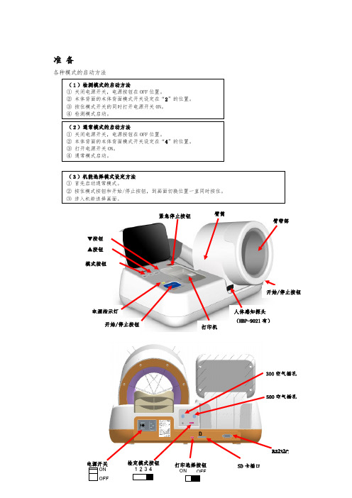
准备
各种模式的启动方法
(1)检测模式的启动方法 ① 关闭电源开关,电源按钮在 OFF 位置。 ② 本体背面的本体背面模式开关设定在“2”的位置。 ③ 按住模式开关的同时打开电源开关 ON。 ④ 检测模式启动。
(2)通常模式的启动方法 ① 关闭电源开关,电源按钮在 OFF 位置。 ② 本体背面的本体背面模式开关设定在“4”的位置。 ③ 打开电源机能选择模式设定方法 ① 首先启动通常模式。 ② 按住模式按钮和开始/停止按钮,到画面切换位置一直同时按住。
OMRON MEMS流量传感器D6F-V03A1说明书

The unique dust separating structure, developed by OMRON is a compact and highly efficient FLOW-SENSOR.•A dust-resistant design has been taken into consideration, by the original dust segregation structure, of OMRON.•+/-10% Full-Scale repeatable accuracy achieves consistent air velocity measurement.•Applications include clogged-filter detection and air velocity.Sensor specificationAbsolute maximum ratingOutput characteristicMeasurement condition: Power-supply voltage 3.3VDC, ambient temperature 25°C and dry air.Note:1.Air velocity is the value converted from the mass-flow in OMRON regulation wind tunnel phi48mm.2.The air velocity, set to the Measurement Law, is not shown. Please confirm in a real use environment in use.3.T emperature characteristics:Over ambient temperature range -10 to +60°C: within ±20% F .S. of detected characteristics Of at +25°C.Type D6F-V03A1Flow Range 0 – 3 m/s @ 25°C, 1 atmosphere Case Material Thermoplastic resin GasAirAmbient Temperature -10 to +60°C (with no condensation)Using Humidity Max. 85% RH (with no condensation)Storage Temperature -40 to +80°C (with no condensation)Preservation Humidity Max. 85% RH (with no condensation)Power Supply Voltage 3.15 to 3.45 VDCOutput Signal Analog output 0.5 to 2 VDC (non-linear output)Load resistance min. 10k ΩCurrent Consumption Max. 15mA (No-load, V CC = 3.3 VDC, 25°C)Insulation Resistance20Mohm min. (500VDC, between lead terminal and the case)Dielectric Withstanding Voltage Leakage current is 1mA max. (at 500 VAC, 50/60Hz for one minute).500VAC, 50/60Hz judged at 1mA max. (between the lead terminals and the case)ItemSymbol Rating Unit Power supply voltage V CC 12.0VDC Output voltageV OUT3.0VDCFlow Velocity (m/sec)00.75 1.50 2.25 3.00Output Voltage (VDC)0.50±0.150.70±0.151.11±0.151.58±0.152.00±0.15DimensionsOmron Electronic Components, LLCTerms and Conditions of Sales1.Definitions: The words used herein are defined as follows.(a) Terms:These terms and conditions(b) Seller:Omron Electronic Components LLC and its subsidiaries(c) Buyer:The buyer of Products, including any end user in section III through VI(d) Products:Products and/or services of Seller(e) Including:Including without limitation2.Offer; Acceptance: These Terms are deemed part of all quotations, acknowledgments,invoices, purchase orders and other documents, whether electronic or in writing, relating to the sale of Products by Seller. Seller hereby objects to any Terms proposed in Buyer's purchase order or other documents which are inconsistent with, or in addition to, these Terms.3.Distributor: Any distributor shall inform its customer of the contents after and includingsection III of these Terms.1.Prices; Payment: All prices stated are current, subject to change without notice by Seller.Buyer agrees to pay the price in effect at time of shipment. Payments for Products received are due net 30 days unless otherwise stated in the invoice. Buyer shall have no right to set off any amounts against the amount owing in respect of this invoice.2.Discounts: Cash discounts, if any, will apply only on the net amount of invoices sent toBuyer after deducting transportation charges, taxes and duties, and will be allowed only if (a) the invoice is paid according to Seller's payment terms and (b) Buyer has no past due amounts owing to Seller.3.Interest: Seller, at its option, may charge Buyer 1.5% interest per month or the maximumlegal rate, whichever is less, on any balance not paid within the stated terms.4.Orders: Seller will accept no order less than 200 U.S. dollars net billing.5.Currencies: If the prices quoted herein are in a currency other than U.S. dollars, Buyershall make remittance to Seller at the then current exchange rate most favorable to Seller; provided that if remittance is not made when due, Buyer will convert the amount to U.S. dollars at the then current exchange rate most favorable to Seller availableduring the period between the due date and the date remittance is actually made.ernmental Approvals: Buyer shall be responsible for all costs involved in obtainingany government approvals regarding the importation or sale of the Products.7.Taxes: All taxes, duties and other governmental charges (other than general real propertyand income taxes), including any interest or penalties thereon, imposed directly orindirectly on Seller or required to be collected directly or indirectly by Seller for themanufacture, production, sale, delivery, importation, consumption or use of the Products sold hereunder (including customs duties and sales, excise, use, turnover and license taxes) shall be charged to and remitted by Buyer to Seller.8.Financial: If the financial position of Buyer at any time becomes unsatisfactory to Seller,Seller reserves the right to stop shipments or require satisfactory security or payment in advance. If Buyer fails to make payment or otherwise comply with these Terms or any related agreement, Seller may (without liability and in addition to other remedies) cancel any unshipped portion of Products sold hereunder and stop any Products in transit until Buyer pays all amounts, including amounts payable hereunder, whether or not then due, which are owing to it by Buyer. Buyer shall in any event remain liable for all unpaid accounts.9.Cancellation; Etc: Orders are not subject to rescheduling or cancellation unless Buyerindemnifies Seller fully against all costs or expenses arising in connection therewith. 10.Force Majeure: Seller shall not be liable for any delay or failure in delivery resulting fromcauses beyond its control, including earthquakes, fires, floods, strikes or other labor disputes, shortage of labor or materials, accidents to machinery, acts of sabotage, riots, delay in or lack of transportation or the requirements of any government authority.11.Shipping; Delivery: Unless otherwise expressly agreed in writing by Seller:(a) All sales and shipments of Products shall be FOB shipping point (unless otherwisestated in writing by Seller), at which point title to and all risk of loss of the Products shall pass from Seller to Buyer, provided that Seller shall retain a security interest in theProducts until the full purchase price is paid by Buyer;(b) Delivery and shipping dates are estimates only; and(c) Seller will package Products as it deems proper for protection against normalhandling and extra charges apply to special conditions.12.Claims: Any claim by Buyer against Seller for shortage or damage to the Productsoccurring before delivery to the carrier must be presented in detail in writing to Seller within 30 days of receipt of shipment.1.Suitability: IT IS THE BUYER’S SOLE RESPOINSIBILITY TO ENSURE THAT ANYOMRON PRODUCT IS FIT AND SUFFICIENT FOR USE IN A MOTORIZED VEHICLE APPLICATION. BUYER SHALL BE SOLELY RESPONSIBLE FOR DETERMINING APPROPRIATENESS OF THE PARTICULAR PRODUCT WITH RESPECT TO THE BUYER’S APPLICATION INCLUDING (A) ELECTRICAL OR ELECTRONICCOMPONENTS, (B) CIRCUITS, (C) SYSTEM ASSEMBLIES, (D) END PRODUCT, (E) SYSTEM, (F) MATERIALS OR SUBSTANCES OR (G) OPERATING ENVIRONMENT.Buyer acknowledges that it alone has determined that the Products will meet theirrequirements of the intended use in all cases. Buyer must know and observe allprohibitions of use applicable to the Product/s.e with Attention: The followings are some examples of applications for whichparticular attention must be given. This is not intended to be an exhaustive list of all possible use of any Product, nor to imply that any use listed may be suitable for any Product:(a) Outdoor use, use involving potential chemical contamination or electricalinterference.(b) Use in consumer Products or any use in significant quantities.(c) Energy control systems, combustion systems, railroad systems, aviation systems,medical equipment, amusement machines, vehicles, safety equipment, andinstallations subject to separate industry or government regulations.(d) Systems, machines, and equipment that could present a risk to life or property.3.Prohibited Use: NEVER USE THE PRODUCT FOR AN APPLICATION INVOLVINGSERIOUS RISK TO LIFE OR PROPERTY WITHOUT ENSURING THAT THE SYSTEM AS A WHOLE HAS BEEN DESIGNED TO ADDRESS THE RISKS, AND THAT THE PRODUCT IS PROPERLY RATED AND INSTALLED FOR THE INTENDED USEWITHIN THE OVERALL EQUIPMENT OR SYSTEM.4.Motorized Vehicle Application: USE OF ANY PRODUCT/S FOR A MOTORIZEDVEHICLE APPLICATION MUST BE EXPRESSLY STATED IN THE SPECIFICATION BY SELLER.5.Programmable Products: Seller shall not be responsible for the Buyer's programming ofa programmable Product.1.Warranty: Seller's exclusive warranty is that the Products will be free from defects inmaterials and workmanship for a period of twelve months from the date of sale by Seller (or such other period expressed in writing by Seller). SELLER MAKES NO WARRANTY OR REPRESENTATION, EXPRESS OR IMPLIED, ABOUT ALL OTHER WARRANTIES, NON-INFRINGEMENT, MERCHANTABILITY OR FITNESS FOR A PARTICULARPURPOSE OF THE PRODUCTS.2.Buyer Remedy: Seller's sole obligation hereunder shall be to replace (in the formoriginally shipped with Buyer responsible for labor charges for removal or replacement thereof) the non-complying Product or, at Seller's election, to repay or credit Buyer an amount equal to the purchase price of the Product; provided that there shall be noliability for Seller or its affiliates unless Seller's analysis confirms that the Products were handled, stored, installed and maintained and not subject to contamination, abuse,misuse or inappropriate modification. Return of any Products by Buyer must beapproved in writing by Seller before shipment.3.Limitation on Liability: SELLER AND ITS AFFILIATES SHALL NOT BE LIABLE FORSPECIAL, INDIRECT, INCIDENTAL OR CONSEQUENTIAL DAMAGES, LOSS OF PROFITS OR PRODUCTION OR COMMERCIAL LOSS IN ANY WAY CONNECTED WITH THE PRODUCTS, WHETHER SUCH CLAIM IS BASED IN CONTRACT,WARRANTY, NEGLIGENCE OR STRICT LIABILITY. FURTHER, IN NO EVENT SHALL LIABILITY OF SELLER OR ITS AFFILITATES EXCEED THE INDIVIDUAL PRICE OF THE PRODUCT ON WHICH LIABILITY IS ASSERTED.4.Indemnities: Buyer shall indemnify and hold harmless Seller, its affiliates and itsemployees from and against all liabilities, losses, claims, costs and expenses (including attorney's fees and expenses) related to any claim, investigation, litigation or proceeding (whether or not Seller is a party) which arises or is alleged to arise from Buyer's acts or omissions under these Terms or in any way with respect to the Products.1.Intellectual Property: The intellectual property embodied in the Products is the exclusiveproperty of Seller and its affiliates and Buyer shall not attempt to duplicate it in any way without the written permission of Seller. Buyer (at its own expense) shall indemnify and hold harmless Seller and defend or settle any action brought against Seller to the extent that it is based on a claim that any Product made to Buyer specifications infringedintellectual property rights of another party.2.Property; Confidentiality: Notwithstanding any charges to Buyer for engineering ortooling, all engineering and tooling shall remain the exclusive property of Seller. All information and materials supplied by Seller to Buyer relating to the Products areconfidential and proprietary, and Buyer shall limit distribution thereof to its trustedemployees and strictly prevent disclosure to any third party.3.Performance Data: Performance data is provided as a guide in determining suitabilityand does not constitute a warranty. It may represent the result of Seller's test conditions, and the users must correlate it to actual application requirements.4.Change In Specifications: Product specifications and description may be changed at anytime based on improvements or other reasons. It is Seller’s practice to change part numbers when published ratings or features are changed, or when significantengineering changes are made. However, some specifications of the Product may be changed without any notice.5.Errors And Omissions: The information on Seller’s website or in other documentationhas been carefully checked and is believed to be accurate; however, no responsibility is assumed for clerical, typographical or proofreading errors or omissions.6.Export Controls: Buyer shall comply with all applicable laws, regulations and licensesregarding (a) export of the Products or information provided by Seller; (b) sale ofProducts to forbidden or other proscribed persons or organizations; (c)disclosure to non-citizens of regulated technology or information.1.Waiver: No failure or delay by Seller in exercising any right and no course of dealingbetween Buyer and Seller shall operate as a waiver of rights by Seller.2.Assignment: Buyer may not assign its rights hereunder without Seller's written consent.w: These Terms are governed by Illinois law (without regard to conflict of laws). Federaland state courts in Illinois have exclusive jurisdiction for any dispute hereunder.4.Amendment: These Terms constitute the entire agreement between Buyer and Sellerrelating to the Products, and no provision may be changed or waived unless in writing signed by the parties.5.Severability: If any provision hereof is rendered ineffective or invalid, such provision shallnot invalidate any other provision.Certain Precautions on Specifications and UseOMRON ON-LINEGlobal - USA - Cat. No. J01C-E-01Printed in USAOMRON ELECTRONIC COMPONENTS LLC55 E. Commerce Drive, Suite B Schaumburg, IL 60173847-882-228801/07 Specifications subject to change without noticeComplete “Terms and Conditions of Sale” for product purchase and use are on Omron’s website at – under the “About Us” tab, in the Legal Matters section.ALL DIMENSIONS SHOWN ARE IN MILLIMETERS.T o convert millimeters into inches, multiply by 0.03937. To convert grams into ounces, multiply by 0.03527.。
压力传感器计算公式上限值

压力传感器计算公式上限值压力传感器是一种用于测量压力的传感器,它能够将压力转换为电信号输出。
在工业控制、汽车制造、医疗设备等领域都有广泛的应用。
在使用压力传感器时,我们需要了解其上限值,以便正确使用和保护传感器。
本文将详细介绍压力传感器计算公式上限值的相关知识。
首先,我们需要了解什么是压力传感器的上限值。
压力传感器的上限值是指传感器所能承受的最大压力值。
超过这个数值,传感器可能会损坏或出现不准确的测量结果。
因此,了解上限值对于正确选择和使用压力传感器至关重要。
在计算压力传感器的上限值时,我们需要考虑传感器的结构和工作原理。
一般来说,压力传感器的上限值取决于传感器的材料、结构、工作原理等因素。
在选择传感器时,我们需要根据具体的工作环境和测量要求来确定传感器的上限值。
在实际应用中,我们可以通过以下公式来计算压力传感器的上限值:上限值 = 最大工作压力×安全系数。
其中,最大工作压力是指传感器所能承受的最大压力值,通常由传感器的技术参数或厂家提供;安全系数是指在实际使用中为了保证传感器的安全和可靠性而设置的一个系数,通常取1.5-2之间。
举个例子,如果一个压力传感器的最大工作压力为100MPa,安全系数取1.5,那么其上限值为150MPa。
这意味着在实际使用中,传感器所能承受的最大压力值为150MPa,超过这个数值就可能会损坏传感器或导致测量不准确。
在实际应用中,我们还需要考虑到传感器的工作温度、介质、脉冲压力等因素对上限值的影响。
这些因素都会对传感器的上限值产生影响,因此在计算上限值时需要综合考虑各种因素。
总之,压力传感器的上限值是在选择和使用传感器时需要重点考虑的因素之一。
通过合理计算上限值,可以确保传感器在实际使用中能够安全可靠地工作,同时也能够保护传感器免受损坏。
希望本文能够帮助大家更好地理解压力传感器的上限值计算方法,从而更好地选择和使用压力传感器。
OMRON欧姆龙光电传感器
OMRON欧姆龙光电传感器OMRON欧姆龙公司是一家专业从事电器控制、电子设备和自动化技术的日本企业。
公司成立于1933年,随着科技的发展与市场需求的变化,OMRON欧姆龙公司已经逐渐成为全球领先的电气制造商之一。
它的光电传感器是其自动化技术产品中的重要组成部分。
什么是光电传感器?光电传感器是一种常见的传感器类型,其工作原理基于光的特性。
它利用发射器发射出的光束,通过被检测物体反射回来或者经过物体时发生光电反应,进而判断物体是否存在或者物体的某种信息。
光电传感器常用于自动化检测和测量中,能够替代人工进行物体检测和计数的工作。
光电传感器根据测量光源、检测方式、输出方式等不同标准进行分类。
其中,OMRON欧姆龙光电传感器主要用于物体检测和测距等领域,并且在不同场合中选用不同种类的光电传感器。
OMRON欧姆龙光电传感器的特点1. 精度高OMRON欧姆龙光电传感器能够对物体进行快速、准确的检测,可以测量到微小物体,其测量精度高于通常的机械传感器。
同时,它的检测距离也具有较高的可调节性,可以根据实际需求进行灵活的调整。
2. 适用范围广OMRON欧姆龙光电传感器能够应用于各种不同的环境和场合。
例如,它可以用于在加工生产中检测个体物体或者线体,也可以用于自动售货机中物品的检测。
3. 反应时间短OMRON欧姆龙光电传感器反应时间快,达到亚毫秒级别。
这要归功于其光电传感技术的高速度与高效性。
4. 安全性高OMRON欧姆龙光电传感器使用低功率发射器,可以保证在使用过程中的安全性。
其次,当检测到异常情况时,光电传感器也能够立即停止工作,从而保障生产安全。
适用场合OMRON欧姆龙光电传感器广泛应用于机械加工、自动化流水线、食品加工、物流包装等领域。
通过其高效、准确的检测,可以提高生产效率并降低成本,同时还能确保产品质量和安全性。
例如,在食品加工业中,OMRON欧姆龙的光电传感器可以对水果、蔬菜、肉类和大米等进行检测,控制流水生产线上的物料充实度、等级是否符合标准、存在异物等问题,提高了加工线的质量和安全性。
- 1、下载文档前请自行甄别文档内容的完整性,平台不提供额外的编辑、内容补充、找答案等附加服务。
- 2、"仅部分预览"的文档,不可在线预览部分如存在完整性等问题,可反馈申请退款(可完整预览的文档不适用该条件!)。
- 3、如文档侵犯您的权益,请联系客服反馈,我们会尽快为您处理(人工客服工作时间:9:00-18:30)。
OMRON传感器压力
接近开关是一种无需与运动部件进行机械直接接触而可以操作的位置开关,当物体接近开关的感应面到动作距离时,不需要机械接触及施加任何压力即可使开关动作,从而驱动直流电器或给计算机(plc)装置提供控制指令。
接近开关是种开关型传感器(即无触点开关),它既有行程开关、微动开关的特性,同时具有传感性能,且动作可靠,性能稳定,频率响应快,应用寿命长,抗干扰能力强等、并具有防水、防震、耐腐蚀等特点。
产品有电感式、电容式、霍尔式、交、直流型。
接近开关又称无触点接近开关,是理想的电子开关量传感器。
当金属检测体接近开关的感应区域,开关就能无接触,无压力、无火花、迅速发出电气指令,准确反应出运动机构的位置和行程,即使用于一般的行程控制,其定位精度、操作频率、使用寿命、安装调整的方便性和对恶劣环境的适用能力,是一般机械式行程开关所不能相比的。
它广泛地应用于机床、冶金、化工、轻纺和印刷等行业。
在自动控制系统中可作为限位、计数、定位控制和自动保护环节等。
OMRON传感器压力。