BHX1-LR44-SM, 规格书,Datasheet 资料
XNX系列氢氧化物传感器的产品介绍说明书
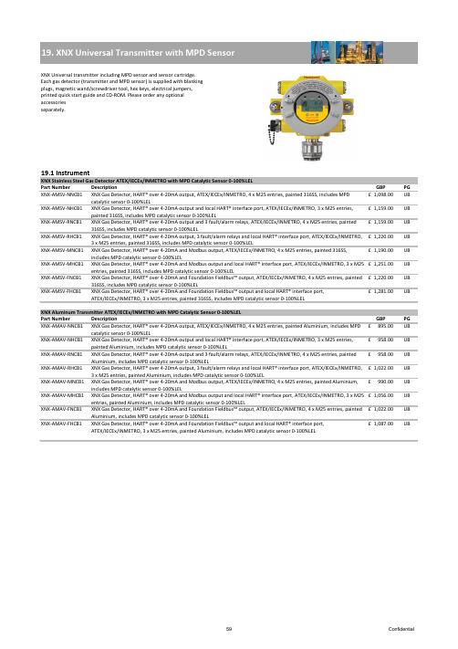
XNX Gas Detector, HART® over 4-20mA output, ATEX/IECEx/INMETRO, 4 x M25 entries, painted 316SS, includes MPD XNX Gas Detector, HART® over 4-20mA output and local HART® interface port, ATEX/IECEx/INMETRO, 3 x M25 entries, XNX Gas Detector, HART® over 4-20mA output and 3 fault/alarm relays, ATEX/IECEx/INMETRO, 4 x M25 entries, painted6970Confidential71Confidential72Confidential73ConfidentialPart NumberDescriptionPGXNX-AMAE-FNNNN XNX Transmitter, HART® over 4-20mA and Foundation Fieldbus™ output, ATEX/IECEx/INMETRO, 4 x M25 entries, painted Aluminium, configured for XNX toxic and oxygen sensors895.00£ UB XNX-AMAE-FHNNNXNX Transmitter, HART® over 4-20mA and Foundation Fieldbus™ output and local HART® interface port, ATEX/IECEx/INMETRO, 3 x M25 entries, painted Aluminium, configured for XNX toxic and oxygen sensors958.00£ UBXNX Stainless Steel Transmitter UL/CSA for use with XNX Toxic and Oxygen Sensors Part Number Description GBP PGXNX-UTSE-NNNNN XNX Transmitter, HART® over 4-20mA output, UL/CSA, 4 x 3/4"NPT entries, painted 316SS, configured forXNX toxic and oxygen sensors975.00£ UB XNX-UTSE-NHNNN XNX Transmitter, HART® over 4-20mA output and local HART® interface port, UL/CSA, 3 x 3/4"NPTentries, painted 316SS, configured for XNX toxic and oxygen sensors1,037.00£ UB XNX-UTSE-RNNNN XNX Transmitter, HART® over 4-20mA output and 3 fault/alarm relays, UL/CSA, 4 x 3/4"NPT entries,painted 316SS, configured for XNX toxic and oxygen sensors1,037.00£ UB XNX-UTSE-RHNNN XNX Transmitter, HART® over 4-20mA output and 3 fault/alarm relays and local HART® interface port,UL/CSA, 3 x 3/4"NPT entries, painted 316SS, configured for XNX toxic and oxygen sensors 1,098.00£ UB XNX-UTSE-MNNNN XNX Transmitter, HART® over 4-20mA and Modbus output, UL/CSA, 4 x 3/4"NPT entries, painted 316SS, configured for XNX toxic and oxygen sensors1,068.00£ UB XNX-UTSE-MHNNN XNX Transmitter, HART® over 4-20mA and Modbus output and local HART® interface port, UL/CSA, 3 x 3/4"NPT entries, painted 316SS, configured for XNX toxic and oxygen sensors1,128.00£ UB XNX-UTSE-FNNNN XNX Transmitter, HART® over 4-20mA and Foundation Fieldbus™ output, UL/CSA, 4 x 3/4"NPT entries, painted 316SS, configured for XNX toxic and oxygen sensors1,098.00£ UB XNX-UTSE-FHNNNXNX Transmitter, HART® over 4-20mA and Foundation Fieldbus™ output and local HART® interface port, UL/CSA, 3 x 3/4"NPT entries, painted 316SS, configured for XNX toxic and oxygen sensors1,159.00£ UBXNX Aluminium Transmitter UL/CSA for use with XNX Toxic and Oxygen Sensors Part Number Description GBP PGXNX-UTAE-NNNNN XNX Transmitter, HART® over 4-20mA output, UL/CSA, 4 x 3/4"NPT entries, painted Aluminium,configured for XNX toxic and oxygen sensors767.00£ UB XNX-UTAE-NHNNN XNX Transmitter, HART® over 4-20mA output and local HART® interface port, UL/CSA, 3 x 3/4"NPTentries, painted Aluminium, configured for XNX toxic and oxygen sensors831.00£ UB XNX-UTAE-RNNNN XNX Transmitter, HART® over 4-20mA output and 3 fault/alarm relays, UL/CSA, 4 x 3/4"NPT entries,painted Aluminium, configured for XNX toxic and oxygen sensors831.00£ UB XNX-UTAE-RHNNN XNX Transmitter, HART® over 4-20mA output and 3 fault/alarm relays and local HART® interface port,UL/CSA, 3 x 3/4"NPT entries, painted Aluminium, configured for XNX toxic and oxygen sensors 895.00£ UB XNX-UTAE-MNNNN XNX Transmitter, HART® over 4-20mA and Modbus output, UL/CSA, 4 x 3/4"NPT entries, painted Aluminium, configured for XNX toxic and oxygen sensors863.00£ UB XNX-UTAE-MHNNN XNX Transmitter, HART® over 4-20mA and Modbus output and local HART® interface port, UL/CSA, 3 x 3/4"NPT entries, painted Aluminium, configured for XNX toxic and oxygen sensors927.00£ UB XNX-UTAE-FNNNN XNX Transmitter, HART® over 4-20mA and Foundation Fieldbus™ output, UL/CSA, 4 x 3/4"NPT entries, painted Aluminium, configured for XNX toxic and oxygen sensors895.00£ UB XNX-UTAE-FHNNNXNX Transmitter, HART® over 4-20mA and Foundation Fieldbus™ output and local HART® interface port, UL/CSA, 3 x 3/4"NPT entries, painted Aluminium, configured for XNX toxic and oxygen sensors958.00£ UB74Confidential75Confidential76Confidential77ConfidentialXNX Aluminuim Transmitter ATEX/IEC for use with Optima Plus and Searchline Excel Detectors78ConfidentialXNX Aluminuim Transmitter UL/CSA for use with Optima Plus and Searchline Excel DetectorsExcel kits including standard XNX transmitter configured with HART® over 4-20mA output and local IS HART® port. For Excel kits includingother XNX transmitter configurations contact Honeywell Analytics. A calibration has to be ordered with every XNX Excel kit.Excel gas calibration curve to be selected from section 29.2 and to be ordered additionally.23.1 InstrumentExcel kits including standard XNX transmitter with HART® over 4-20mA outputs and local IS HART® port.Excel Short Range 5m – 40m (15ft - 130ft)Part Number Description GBP PG 02104-N-XSAA XNX Excel line-of-sight gas detection system, short range (5 to 40m), 4 to 20mA and HART® outputs, ATEX/IECEx, fully wired with flexible conduit, electro polished 316SS. Includes Tx, Rx, aluminimum XNX, Ex e junction box with M20/M25 cable entries, 316SS mounting plates, brackets and hardware 6,518.00£ UA02104-N-XSSAXNX Excel line-of-sight gas detection system, short range (5 to 40m), 4 to 20mA and HART® outputs, ATEX/IECEx, fully wired with flexible conduit, electro polished 316SS. Includes Tx, Rx, stainless steel XNX, Ex e junction box with M20/M25 cable entries, 316SS mounting plates, brackets and hardware6,649.00£ UA 02104-N-XSAUXNX Excel line-of-sight gas detection system, short range (5 to 40m), 4 to 20mA and HART® outputs, UL, fully wired with flexible conduit, electro polished 316SS. Includes Tx, Rx, aluminimum XNX, junction box with 3/4"NPT cable entries, 316SS mounting plates, brackets and hardware6,827.00£ UA 02104-N-XSSUXNX Excel line-of-sight gas detection system, short range (5 to 40m), 4 to 20mA and HART® outputs, UL, fully wired with flexible conduit, electro polished 316SS. Includes Tx, Rx, stainless steel XNX, junction box with 3/4"NPT cable entries, 316SS mounting plates, brackets and hardware6,960.00£ UA 02104-N-XSACXNX Excel line-of-sight gas detection system, short range (5 to 40m), 4 to 20mA and HART® outputs, FM/CSA, fully wired with flexible conduit, electro polished 316SS. Includes Tx, Rx, aluminimum XNX, junction box with 3/4"NPT cable entries, 316SS mounting plates, brackets and hardware6,539.00£ UA 02104-N-XSSCXNX Excel line-of-sight gas detection system, short range (5 to 40m), 4 to 20mA and HART® outputs, FM/CSA, fully wired with flexible conduit, electro polished 316SS. Includes Tx, Rx, stainless steel XNX, junction box with 3/4"NPT cable entries, 316SS mounting plates, brackets and hardware6,671.00£ UA 02104-N-NSNAExcel line-of-sight gas detection system (without XNX, please order required XNX separately), short range (5 to 40m), 4 to 20mA output, ATEX/IECEx, fully wired with flexible conduit, electro polished 316SS. Includes Tx, Rx, 316SS mounting plates, brackets and hardware. XNX and junciton boxes to be ordered seperately.5,591.00£ UA83Confidential。
LR1154(LR44)新规格书

丰力电池有限公司ALKALINE ZINC-MANGANESE DIOXIDE MERCURY-FREE BUTTON CELL型号(MODEL):LR44 0.0Hg碱性锌锰扣式电池TECHNICAL SPECIFICATION技术规格书制定:Huang Ting Piao申批:Hong ze hong规格编号:CKJ.FL-LR44版本号:2015-A44-1日期:2015-03(本公司有更改产品规格书及任何资料的权力,且无须预先通知。
)第1页,共6页负载电阻:7.5k扣式碱性电池LR441、Scope 适用范围This specification is applicable to our Accell alkaline zinc –manganese dioxide mercury-free button cell :LR44该规格书适用于由丰力电池有限公司碱性锌-二氧化锰无汞扣式电池:LR44。
2、产品类型TYPE名称Model:LR44(LR1154)IEC命名:LR443、化学构成分子式CHEMICAL STRUCTURE(+)锌--二氧化锰(碱性电解液) (-) Zn|KOH|MnO2汞含量测试结果(TESTING RESULT OF MERCURY) :Hg<5ppm(0.0005%)镉含量测试结果(TESTING RESULT OF NICKLE) :Cd<5ppm(0.0005%)铝含量测试结果(TESTING RESULT OF ALUMINIUM) :Pb<5ppm(0.0005%)4、技术规格PRODUCT SPECIFICATION4.1规格尺寸高度(H)5.40mm直径(Φ)11.60mm4.2平均重量 Average weight: 1.86g4.3额定电压 Nommal voltage 1.50V4.4典型容量Typical capacity: 120mAh(在20±2℃条件下,用1KΩ负载电阻连续放电,终止电压0.90V)。
海斯特产品目录(彩色)

佛山市海斯特密封技术有限公司佛山市海斯特密封技术有限公司地址:广东省佛山市禅城区平远北街平西新村15号3楼东邮编:528041电话:+86-0757-******** / 83134290 / 83819359 / 83875181 / 83875182传真:+86-0757-******** / 83819359网址: 邮箱:sales@Add:15Pingxi Xincun ,Pingyuan Street North,Suite3A, Foshan,Guangdong PC.:528041T e l :+86-0757-******** / 83134290 / 83819359 / 83875181 / 83875182Fax:+86-0757-******** / 83819359Web: E-mail:sales@Foshan Hiseal Industry and Trade Co.,Ltd密封设计选型指南密封设计选型指南佛山市海斯特密封技术有限公司目 录目 录密封件一览表活塞密封活塞杆密封防尘圈耐磨环旋转密封弹簧施力密封O形圈其它密封安装指南质量及贮存准则27 51 75 119 133 139 151 157 161163活塞密封:活塞杆密封:防尘圈:耐磨环:旋转密封:弹簧施力密封:O 形圈:H30活塞密封H30活塞密封双向活塞密封密封件一览表注:以上表中以及本书中所列工作参数数据是最大值,各参数之间相互制约,相互关联,因度范围也与具体工作介质密切相关。
此不能同时使用。
比如最高压力取决于具体材料类型、工作温度、速度和间隙尺寸等,而温表面粗糙度 Ra 0.05-0.3<1.6Rz <1.6<10.0Rmax.<2.5<16.0配合表面µm 沟槽表面µm 1.说明H30活塞密封是双向作用的活塞密封,由一个填充聚四氟乙烯密封环和一个O形圈组成。
Schneider Electric XUSL4E14F031N 产品数据手册说明书

T h e i n f o r m a t i o n p r o v i d e d i n t h i s d o c u m e n t a t i o n c o n t a i n s g e n e r a l d e s c r i p t i o n s a n d /o r t e c h n i c a l c h a r a c t e r i s t i c s o f t h e p e r f o r m a n c e o f t h e p r o d u c t s c o n t a i n e d h e r e i n .T h i s d o c u m e n t a t i o n i s n o t i n t e n d e d a s a s u b s t i t u t e f o r a n d i s n o t t o b e u s e d f o r d e t e r m i n i n g s u i t a b i l i t y o r r e l i a b i l i t y o f t h e s e p r o d u c t s f o r s p e c i f i c u s e r a p p l i c a t i o n s .I t i s t h e d u t y o f a n y s u c h u s e r o r i n t e g r a t o r t o p e r f o r m t h e a p p r o p r i a t e a n d c o m p l e t e r i s k a n a l y s i s , e v a l u a t i o n a n d t e s t i n g o f t h e p r o d u c t s w i t h r e s p e c t t o t h e r e l e v a n t s p e c i f i c a p p l i c a t i o n o r u s e t h e r e o f .N e i t h e r S c h n e i d e r E l e c t r i c I n d u s t r i e s S A S n o r a n y o f i t s a f f i l i a t e s o r s u b s i d i a r i e s s h a l l b e r e s p o n s i b l e o r l i a b l e f o r m i s u s e o f t h e i n f o r m a t i o n c o n t a i n e d h e r e i n .Product data sheetCharacteristicsXUSL4E14F031NXUSL type 4 - Finger protection - Std sensingrange - Hp = 310 mm, R=14mmProduct availability: Non-Stock - Not normally stocked in distribution facilityMainRange of product Preventa Safety detection Product or component typeSafety light curtain type 4Device short name XUSL4EOutput type2 safety outputs OSSD solid-state PNP arc suppres-sion)Product specific applica-tionFor finger protection [R] Resolution 0.55 in (14 mm)[Sn] nominal sensing distance3.28…19.69 Ft (1…6 m) by cabling 0.00…9.84 ft (0…3 m) by cabling [Hp] Height protected 12.20 in (310 mm)Number of beams 30Type of start / restart Manual Automatic External Device Moni-toring (EDM)Selected by wiringComplementaryDetection system Transmitter-receiver system Response time 5.5 msKit compositionAdjustable mounting bracket(s)1 receiver(s)1 transmitter(s)1 user guide with certificate of conformity on CD-ROM [EAA] effective aperture angle 2.5 ° at 3 mEmissionIR LED 0.000037402 in (950 nm)[Us] rated supply voltage 24 V DC +/- 20 %SupplyPower supply IEC 61496-1Power supply IEC 60204-1[Ie] rated operational current 2 ACurrent consumption42 mA no-load transmitter 83 mA no-load receiver 42 mA transmitter900 mA with maximum load receiver Output current limits 0.4 A safety outputs OSSD Output voltage 24 V Output circuit type DC Maximum voltage drop <0.5 VLocal signalling 1 multi-colour LED transmitter 2 dual colour LEDs receiverElectrical connection 1 male connector M12 5 pins transmitter 1 male connector M12 8 pins receiverFunction availableTestMuting through external safety module XPSLCMUT1160LED display of operating modes and faults Marking CEMaterialAluminium casingPolycarbonate front panel Polypropylene end caps Housing colourRed RAL 3000Fixing mode By fixing bracketsNet weight 1.54 lb(US) (0.7 kg)Offer type Standard distanceEnvironmentDirectives89/336/EEC - electromagnetic compatibility2002/95/EC - RoHS directive98/37/EEC - machinery89/655/EEC - work equipment2002/96/EC - WEEE directiveProduct certifications CULusCETÜVSafety level (correctly wired)Type 4 IEC 61496-1SIL 3 IEC 61508SILCL 3 IEC 62061Category 4 EN/ISO 13849-1PL = e EN/ISO 13849-1Optical characteristic Resistance to light disturbance EN/IEC 61496-2Mission time20 year(s)Safety reliability data PFHd = 1.27E-8 1/h IEC 61508Ambient air temperature for operation-10…55 °C (14…131 °F)-4…131 °F (-20…55 °C)Ambient air temperature for storage-31…158 °F (-35…70 °C)-25…70 °C (-13…158 °F)Relative humidity0…95 % without condensationIP degree of protection IP65IP67Shock resistance10 gn 16 ms IEC 61496-1Vibration resistance0.35 +/- 0.05 mm 10…55 Hz)IEC 61496-1Ordering and shipping detailsCategory22455 - LIGHT CURTAINS - XUSLDiscount Schedule DS2GTIN00785901735632Package weight(Lbs) 1.58 kg (3.49 lb(US))Returnability YesCountry of origin ITOffer SustainabilitySustainable offer status Green Premium productREACh Regulation REACh DeclarationEU RoHS Directive Pro-active compliance (Product out of EU RoHS legal scope)EU RoHS Decla-rationToxic heavy metal free YesMercury free YesRoHS exemption information YesEnvironmental Disclosure Product Environmental ProfileCircularity Profile End Of Life InformationContractual warrantyWarranty18 monthsDimensions Drawings DimensionsBrackets DimensionsMounting and Clearance Mounting and Clearance(1)Insert(2)Bracket(3)Washer(4)Spring washer(5)NutConnections and SchemaWiring DiagramsTransmitter Connections(1)+24 Vdc(2)Configuration_0(3)0 Vdc(4)Configuration_1(5)FEReceiver Connections(1)OSSD1(2)+ 24 V(3)OSSD2(4)Configuration_A(5)K1_K2 Feeback/Restart(6)Configuration_B(7)0 Vdc(8)FEReceiver Configurations and Operating ModesAutomatic Start/RestartWithout External Device Monitoring (EDM) feedback loopWith External Device Monitoring (EDM) feedback loopManual Start/RestartWithout External Device Monitoring (EDM) feedback loop(1)RestartWith External Device Monitoring (EDM) feedback loop(1)RestartConnecting to a Safety Interface1 :Click on Download & Documents2 :Click on Application solutionsTo have all connection schematics concerning our safety module, select "download and document" and download the file "Safety lightcurtains association with safety interfaces"。
伊玛产品类别

18~36 VDC
PNP NO/NC,NPN NO/NC
4~20 mA,0~10 V
可
PA1108
智慧型
7 LED
内螺纹
G 1/4
400 bar
四线
18~36 VDC
PNP NO/NC,NPN NO/NC
4~20 mA,0~10 V
可
PA1109
智慧型
7 LED
内螺纹
G 1/4
2 bar
四线
18~36 VDC
200
60
M12
接插件
N
Y
N
IP67
否
IA0031
齐平
brass
10~36VDC
1
两线
NO
DC PNP/NPN
200
60
M12
接插件
N
Y
N
IP67
否
IA0032
齐平
brass
10~36VDC
1
两线
NC
DC PNP/NPN
200
60
M12
接插件
N
Y
N
IP67
否
IA0033
非齐平
brass
10~36VDC
可
TA1099
智慧型
7 LED
内螺纹
M18 X 1.5
-40~150°C
四线
20~30 VDC
PNP NO/NC,NPN NO/NC
4~20 mA,0~10 V
可
产品类别
压力变送器(模拟量输出)
压力变送器(开关量输出)
订货号
功能
显示
牙口形式
Schmersal PROTECT系列产品说明书
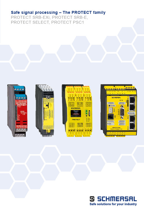
Depending on the complexity and number of safety circuits, the Schmersal Group provides solutions for reliable signal analysis based on safety control modules and safety controllers with an array of visualisation and diagnostic possibilities.PROTECT SRB modules ■ M ulti-purpose use, easy installation, low cost solution ■ S RB-E-series covers a broad range of applications with eight versions ■ S RB EXi modules with ATEX, IECEx and INMETRO approvals ■ S RB301ST for lift applications,certified in accordance with EN 81-20/50Safe signal processingThe complete Schmersal portfolioPROTECT- SELECT ■ U p to 6 safety functions can be realised ■ A daptation to individual requirements thanks to simple parameterisation ■ V arious parameters such as short circuit monitoring can be configured ■ S ave space in the control cabinet ■ D isplay of clear text messages duringtroubleshootingComplexSafety relay module PROTECT SRB-ESafety controller PROTECT PSCPROTECT SELECT safety moduleHigh costLow costSimpleNumber of safety functions1 - 34 - 9> 10Modular safety compact controller PROTECT PSC1■Freely programmable compact controller PSC1-C-10 and PSC1-C-100■ P rogramming software SafePLC2: Modern, object oriented application development environment ■ »Save Drive Monitoring« module (SDM) monitors up to 12 axes ■ U niversal communication interface for all common field-bus systems ■ M odular expansion with up to 272 inputs/ outputsCentral structure:I/O expansion modulesModular compact controller PROTECT PSC1PROTECT PSC1-C-10: up to 2 expansion modules / 64 I/OsPROTECT PSC1-C-100: up to 8 expansion modules / 272 I/OsThe compact controller PROTECT PSC1-C-10 can be expanded with up to 2 I/O expansion modules.A mixture of centralised and decentralised structures can be used.The compact controller PROTECT PSC1-C-100 can be expanded with up to 8 I/O expansion modules.A mixture of centralised and decentralised structures can be used.Central structure:I/O expansion modulesDecentral structure:Expandable with the remote I/O moduleDecentral structure:Expandable with theremote I/O module• • •Safe Drive Monitoring (SDM) for PROTECT PSC 1Safe drive monitoring for up to 12 axesFor safe drive monitoring many safety features are supported:■ S afe shut-down: Safe Torque OFF (STO), Safe Brake Control (SBC)■ S afe stopping: Safe Stop 1 (SS1), Safe Stop 2 (SS2), Safe Operating Stop (SOS)■ S afe movement: Safely-Limited Speed (SLS), Safe Speed Range (SSR), Safe Direction (SDI),Safely-Limited Acceleration (SLA), Safe Acceleration Range (SAR)■ S afe monitoring: Safe Speed Monitor (SSM), Safe Cam (SCA)■ S afe Positioning: Safely-Limited Position (SLP), Safely-Limited Increment (SLI),Safely Emergency Limit (SEL)The drive monitoring is carried out depending on the application requirements, with one or two encoder systems.The following encoder signals are supported:■ 1 encoder system: TTL, SIN/COS, SSI (Gray code / binary code)■ 2 Encoder systems: TTL, SIN/COS, SSI (Gray code / binary code), Resolver, HTLPROTECT - SELECTMulti-functional Safety Module with Program Selection Function With the multi-functional PROTECT SELECT compact safety module, the engineer has greater flexibilityduring configuration of the safety device and its subsequent integration into the machine functions.Four different programs are available. Each program can beprecisely adapted – without any programming knowledge,simply with the menu and clear text messages – to the specificapplication case. This allows for example the release delayand the de-bounce time to be set individually, and numerousparameters such as the cross-wire monitoring to be set asrequired – a definite advantage in comparison to safety relaymodules.With every application program the user profits from numerousfunctions – such as:■C onnection of up to six dual-channel safety switching devices(with or without potential) up to PL e / SIL 3■S afety semi-conductor and relay outputs with STOP 0 orSTOP 1 function■S afe analogue monitoring of temperature and other processvariables■F ree assignment of start-up tests, periodic tests, auto-start,manual start■C ross-wire detection■ Display of clear text messages during troubleshooting■ Input filter for safety devices with contact bouncePROTECT SRB-E modulesSafe signal processing for a range of applicationsAll eight versions of the new family of safety relay modules PROTECT SRB-E can be used in applications up toCat. 4 / PL e in accordance with EN ISO 13849-1 and up to SIL 3 in accordance with EN 62061 / IEC 61508.A major advantage of the new PROTECT SRB-E series is its multi-functionality which allows all the variants to be usedwith several dozen existing SRB modules. Each module can be configured for up to eleven different applications via asimple control element. All conventional safety sensors and electromechanical safety equipment can be monitored.The drastic reduction in the number of variants and the clear display of the relevant functions makes it considerablyeasier for the machine manufacturer to select the right module for their particular application. Adjustable configuration and applicationsFlexible■1 or 2 channel signal evaluation■C ontact configuration can be selected for the sensors■S tart / Reset functionswith monitoring■I nput expanders for4 sensors up to PL e■C ascading via safe inputs■C ombined evaluationfor 2 safety guards■T wo-hand control monitoring ■S TOP Category 0 and 1■U p to 5 safety outputs■S afety category 4, PL e semi-conductor outputsup to 5.5 ACompact■I nstallation width for all devicevariants 22.5 mm■U p to 10 safe inputs and5 safe outputs■U p to 4 signalling outputs■H older for equipment label■U p to 24 connecting terminals User-friendly■U p to 11 different applicationscan be selected■M onitoring of all conventionalsafety switchgear■S afety level of up to PL e / SIL 3can be achieved■S imple adjustmentusing rotary switch■S elected application canbe locked using seal■Q uick response time (< 10 ms)to request■E xcellent switching performanceand short cycle times■S lot-in terminationwith codingFunction setting via rotary knob modeAdjustment of drop-out delay (stop category 1)via rotary switch for timeConnection option for all standard safety switchgearPROTECT SRB-EXi modules Safe signal processing withthe intrinsic safety of ignition protectionThese devices combines functional safety, reliable signal analysis and safety approval with explosion protection. They monitor the connected sensors, reset buttons,emergency stop devices, locking mechanisms and safety sensors with the intrinsic safety of the "i" ignition protection.The sensors can be installed or implemented in zones 1 / 2 and 21 / 22.The PROTECT SRB-EXi modules can be installed in a suitable switching cabinet in gas explosion safety zone 2.Approvals category (2) GD / 3 G:■A TEX ■I ECEx ■I NMETROUser SoftwareProgramming software SafePLC2Programming software SafePLC2 for PROTECT PSC1■M odern, object oriented application development environment■P reconfigured elements for safe electronic and electromechanicalswitching devices■E asy reuse of application code by macros■P rogramming assistance by various search functions■S imple signal tracking by different colour representation andstatus messages■E asy to detect safety functions through practice oriented librariesfor logic,Safe Drive Monitoring, SD-bus and encoder elements■C onfigurable user permissionsThe Schmersal GroupThe details and data referred to have been carefully checked. Technical amendments and errors possible.In the demanding field of machine safety, the owner-managed Schmersal Group is one of the international market leaders. The company, which was founded in 1945,has a workforce of about 2000 people and seven manufacturing sites on three continents along with its own companies and sales partners in more than 60 nations.Customers of the Schmersal Group include global players from the area of mechanical engineering and plant manufacturing as well as operators of machinery. They profit from the company‘s extensive expertise as a provider of systems and solutions for machine safety. Furthermore, Schmersal specialises in various areas including foodstuff production, the packaging industry, machine tool industry, lift switchgear, heavy industry and the automotive industry.A major contribution to the systems and solutions offered by the Schmersal Group is made by tec.nicum with its comprehensive range of services: certified Functional Safety Engineers advise machinery manufacturers and machinery operators in all aspects relating to machinery andoccupational safety – and do so with product and manufacturer neutrality. Furthermore, they plan and realise complex solutions for safety around the world in close collaboration with the clients.Safety Products Safety Systems Safety Services■ Safety switches and sensors, solenoid interlocks■ Safety controllers and safetyrelay modules, safety bus systems ■ Optoelectronic and tactile safety devices■ Automation technology:position switches, proximity switches ■ tec.nicum academy – Seminars and training ■ tec.nicum consulting – Consultancy services ■ tec.nicum engineering –Design and technical planning ■ tec.nicum integration – Execution and installation■ Complete solutions for safeguarding hazard areas ■ Individual parametrisation and programming of safety controllers ■ Tailor-made safety technology –be it for individual machines or a complex production line■ Industry-specific safety solutions 2.000 / L+W / 11.2017 / Teile-Nr. 103014039 / EN / Ausgabe 02*103014039#。
FOXBORO I A Series HARDWARE产品规格说明书

FOXBORO ®The FBM214 HART ® Communication Input Interface Module provides eight input channels, each accepting a 4 to 20mA analog signal or a digital HART signal superimposed on a 4 to 20 mA analog input signal.FEATURESKey features of the FBM214 module are:Eight analog input channels, each accepting oneof the following inputs:•Standard 4 to 20 mA analog sensor signal •Digital HART Frequency Shift Keying (FSK) signal superimposed on a 4 to 20 mA analog input signal.FSK modem dedicated to each input channel forbi-directional digital communications with a HART field deviceAnalog to digital conversion of each of the 4to20mA input signals from the HART devicesSupport for the HART universal commandsnecessary to interface the field device with the I/A Series ® system databaseGalvanic isolation of the group of 8 inputchannels from ground and module logicCompact, rugged design suitable for enclosure inClass G3 (harsh) environmentsHigh accuracy achieved by sigma-delta dataconversions for each channelTermination Assemblies (TAs) for locally orremotely connecting field wiring to the FBM214Termination Assemblies for per channel internallyand/or externally loop powered transmitters.PSS 21H-2Z14 B4 Page 2OVERVIEWThe FBM214 HART Communication Input Interface Module contains eight 4to20mA group isolated analog input channels. The FBM214 supports any mix of standard 4to20mA devices and HART devices.The FBM214 serves as a HART communications field device host, enabling the I/A Series system to request and receive two digital messages per second from the field device. The message pass-through capability can be used to support HART universal, common practice, and device-specific commands, but not the burst communication mode. These commands are implemented using the Intelligent Field Device Configurator (IFDC — refer toPSS 21S-8A3 B3 for details).The FBM214 provides a common isolated power supply to power all eight channels. Optionally, the channels can be powered by an external power supply. However, when a common external power supply is used with two or more channels, a Cable Balun module is required to prevent channel cross talk.COMPACT DESIGNThe FBM214 has a compact design, with a rugged extruded aluminum exterior for physical protection of the circuits. Enclosures specially designed for mounting the FBMs provide various levels of environmental protection, up to harsh environments per ISA Standard S71.04.HIGH ACCURACYFor high accuracy, the module incorporates a Sigma-Delta converter which can provide new analog input values for each channel every 100 milliseconds.VISUAL INDICATORSLight-emitting diodes (LEDs) incorporated into the front of the module provide visual indication of the module’s operational status, and communication activity on the channels.EASY REMOVAL/REPLACEMENTThe module can be removed/replaced without removing field device termination cabling, power, or communications cabling.FIELDBUS COMMUNICATIONA Fieldbus Communication Module or a Control Processor interfaces the redundant 2 Mbps module Fieldbus used by the FBMs. The FBM214 module accepts communication from either path (A or B) of the redundant 2 Mbps fieldbus – should one path fail or be switched at the system level, the module continues communication over the active path.The use of an external power supply common to two or more loops requires a Cable Balun Module to maintain communication signal line balance.MODULAR BASEPLATE MOUNTINGThe module mounts on a modular baseplate which accommodates up to four or eight FBMs. The modular baseplate is either DIN rail mounted or rack mounted, and includes signal connectors for redundant fieldbus, redundant independent dc power, and termination cables.TERMINATION ASSEMBLIESField input signals connect to the FBM subsystem via DIN rail mounted TAs. The TAs used with theFBM214 are described in “TERMINATION ASSEMBLIES AND CABLES” on page8.PSS 21H-2Z14 B4Page 3CABLE BALUN MODULEThe Cable Balun module is used to maintain digital communication line balance for HART Transmitter to FBM loops that are powered from a common external power supply. This powering effectively connects one line of each loop together. Without the Baluns, in each loop so powered, the common connection at the external power supply, would cause near end crosstalk at the system end of the loop wiring cable. Loops using FBM internal power source do not require Baluns.The Cable Balun module contains multiple Baluns. One Balun segment is interconnected in each loop powered from an external power supply per the diagram above. There is one Cable Balun module.Figure 1. Cable Balun Module Cable Balun ModuleModule Model ModulePart No.No. of Balunsin the ModuleCBM-4P0903SV4PSS 21H-2Z14 B4Page 4FUNCTIONAL SPECIFICATIONSField Device ChannelsVERSION SUPPORTEDHART Protocol v6INTERFACE8 group-isolated channelsCOMMUNICATION TO THE DEVICEPoint-to-point, master/slave, asynchronous, half-duplex, at 1200 baud.ERROR CHECKINGParity on each byte, and one CRC check byte.SPEED2 messages per secondFASTEST ALLOWED ECB BLOCK PERIOD500 msecMAXIMUM DISTANCE (FBM214 TO FIELDDEVICE)Meets HART FSK physical layer specificationHCF_SPEC-54, Revision 8.1 [up to 3030 m(10000ft)](1).COMPLIANCE VOLTAGE18 V dc minimum at 20.5 mACURRENT INPUTSSense Resistor61.9 Ω nominalTotal Input Resistance280 Ω minimumAccuracy (Includes Nonlinearity)±0.03% of full scaleTemperature Coefficient50 ppm/ºCResolution15 bitsUpdate Rate100 msIntegration Time500 msCommon Mode Rejection>100 db at 50 or 60 HzNormal Mode Rejection>35 db at 50 or 60 HzMAXIMUM LOOP RESISTANCE280 Ω (not including the field device)(2)LOOP POWER SUPPLY PROTECTIONEach channel is galvanically group isolated,current limited and voltage regulated. All inputsare limited by their design to less than 30 mA. Ifthe current limit circuit shorts out, the current islimited to about 85 mA.FBM INPUT IMPEDANCE280 Ω minimumFBM INTERNAL POWER FOR FIELD DEVICE24 V dc ±10% common power supply for allchannels. Loop load limited to one device perchannel.ISOLATIONThe channels are not galvanically isolated fromeach other, but are galvanically isolated (bothoptical and transformer isolation) as a group from ground and module logic. Inputs use an internal FBM isolated power supply for field power. Themodule withstands, without damage, a potential of 600 V ac applied for one minute between the group-isolated channels and earth (ground).CAUTIONThis does not imply that these channels areintended for permanent connection tovoltages of these levels. Exceeding the limitsfor input voltages, as stated elsewhere in thisspecification, violates electrical safety codesand may expose users to electric shock. Fieldbus CommunicationCommunicates with its associated FCM or FCP via the redundant 2 Mbps module FieldbusHEAT DISSIPATION4 W (maximum)(1)The maximum allowable distance decreases when the loop is operated through an intrinsic safety barrier. The maximum distance ofthe field device from the FBM is a function of compliance voltage, wire gauge and voltage drop at the device.(2)In an intrinsic safety application, if a zener barrier is used between the FBM and the field device, the power supply must be set at24V dc +5%, -1%. There are no specific constraints with the use of galvanic barriers.PSS 21H-2Z14 B4Page 5 FUNCTIONAL SPECIFICATIONS (CONTINUED)Power RequirementsINPUT VOLTAGE RANGE (REDUNDANT)24V dc ±5%CONSUMPTION7 W (maximum)Regulatory ComplianceELECTROMAGNETIC COMPATIBILITY (EMC) European EMC Directive 89/336/EECMeets:EN 50081-2 Emission standardEN 50082-2 Immunity standardEN 61326 Annex A (Industrial Levels) CISPR 11, Industrial Scientific and Medical(ISM) Radio-frequency Equipment -Electromagnetic Disturbance Characteristics- Limits and Methods of MeasurementMeets Class A LimitsIEC 61000-4-2 ESD ImmunityContact 4 kV, air 8 kVIEC 61000-4-3 Radiated Field Immunity10 V/m at 80 to 1000 MHzIEC 61000-4-4 Electrical FastTransient/Burst Immunity2 kV on I/O, dc power and communicationlinesIEC 61000-4-5 Surge Immunity2kV on ac and dc power lines; 1kV on I/Oand communications linesIEC 61000-4-6 Immunity to ConductedDisturbances Induced by Radio frequencyFields10 V (rms) at 150 kHz to 80 MHz on I/O,dc power and communication linesIEC 61000-4-8 Power Frequency MagneticField Immunity30 A/m at 50 and 60 HzPRODUCT SAFETY (FBM AND CABLE BALUN) Underwriters Laboratories (UL) for U.S. andCanadaUL/UL-C listed as suitable for use inUL/UL-C listed Class I, Groups A-D;Division 2; temperature code T4 enclosurebased systems. These modules are also ULand UL-C listed as associated apparatus forsupplying non-incendive communicationcircuits for Class I, Groups A-D hazardouslocations when connected to specifiedI/A Series® processor modules as describedin the I/A Series DIN Rail MountedSubsystem User’s Guide (B0400FA). Wherepower is supplied by the FBM,communications circuits also meet therequirements for Class2 as defined inArticle725 of the National Electrical Code(NFPA No.70) and Section 16 of theCanadian Electrical Code (CSA C22.1).Conditions for use are as specified in theI/A Series DIN Rail Mounted SubsystemUser’s Guide (B0400FA).European Low Voltage Directive 73/23/EECand Explosive Atmospheres (ATEX) directive94/9/ECCENELEC (DEMKO) certified as EEx nA IICT4 for use in CENELEC certified Zone 2enclosure certified as associated apparatusfor supplying non-incendive field circuits forZone 2, Group IIC, potentially explosiveatmospheres when connected to specifiedI/A Series processor modules as describedin the I/A Series DIN Rail MountedSubsystem User’s Guide (B0400FA). Also,see Table1 on page9.Calibration RequirementsCalibration of the module or termination assembly is not required.PSS 21H-2Z14 B4Page 6ENVIRONMENTAL SPECIFICATIONS(3)OperatingTEMPERATUREModule-20 to +70°C (-4 to +158°F)Termination AssemblyPVC-20 to +50°C (-4 to +122°F)PA-20 to +70°C (-4 to +158°F) RELATIVE HUMIDITY5 to 95% (noncondensing)ALTITUDE-300 to +3,000m (-1,000 to +10,000ft)StorageTEMPERATURE-40 to +70°C (-40 to +158°F)RELATIVE HUMIDITY5 to 95% (noncondensing)ALTITUDE-300 to +12,000m (-1,000 to +40,000ft) ContaminationSuitable for use in Class G3 (Harsh) environments as defined in ISA Standard S71.04, based on exposure testing according to EIA Standard 364-65, Class III. Vibration7.5 m/S2 (0.75 g) from 5 to 500 Hz(3)The environmental limits of this module may be enhanced by the type of enclosure containing the module. Refer to the applicableProduct Specification Sheet (PSS) which describes the specific type of enclosure that is to be used.PSS 21H-2Z14 B4Page 7 PHYSICAL SPECIFICATIONSMountingMODULEFBM214 mounts on a modular baseplate. Thebaseplate can be mounted on a DIN rail(horizontally or vertically), or horizontally on a19-inch rack using a mounting kit. Refer toPSS21H-2W6B4 for details.TERMINATION ASSEMBLYThe TA mounts on a DIN rail and accommodates multiple DIN rail styles including 32mm (1.26in) and 35mm 1.38in).MassMODULE284 g (10 oz) approximateTERMINATION ASSEMBLYCompression181 g (0.40 lb) approximateRing Lug249 g (0.55 lb) approximateDimensions – ModuleHEIGHT102 mm (4 in)114 mm (4.5 in) including mounting lugsWIDTH45 mm (1.75 in)DEPTH104 mm (4.11 in)Dimensions – Termination AssemblySee page10.Part NumbersFBM214 MODULEP0922VTTERMINATION ASSEMBLIESSee “FUNCTIONAL SPECIFICATIONS –TERMINATION ASSEMBLIES” on page8. Termination CablesCABLE LENGTHSUp to 30 m (98 ft)CABLE MATERIALSPolyurethane or Hypalon®/XLPTERMINATION CABLE TYPEType 1 – See Table2 on page9.CABLE CONNECTION – TA25-pin male D-subminiatureConstruction – Termination AssemblyMATERIALPolyvinyl Chloride (PVC), compressionPolyamide (PA), compressionPVC, ring lugFAMILY GROUP COLORGreen – communicationTERMINAL BLOCKS3 tiers, 8 positionsField Termination ConnectionsCOMPRESSION-TYPE ACCEPTED WIRINGSIZESSolid/Stranded/AWG0.2 to 4 mm2/0.2 to 2.5 mm2/24 to 12 AWGStranded with Ferrules0.2 to 2.5 mm2 with or without plastic collarRING-LUG TYPE ACCEPTED WIRING SIZES#6 size connectors (0.375 in (9.5 mm))0.5 to 4 mm2/22 AWG to 12 AWGPSS 21H-2Z14 B4Page 8TERMINATION ASSEMBLIES AND CABLESField input signals connect to the FBM subsystem via DIN rail mounted Termination Assemblies, which are electrically passive.TAs for the FBM214 are available in the following forms: Compression screw type using Polyvinyl Chloride(PVC) materialCompression screw type using Polyamide (PA) material Ring lug type using PVC material.See the following “FUNCTIONAL SPECIFICATIONS –TERMINATION ASSEMBLIES” for a list of TAs used with the FBM214.The FBM214 provides sufficient loop resistance to allow use of the HART Hand-Held Terminal, or PC20 Intelligent Field Device Configurator (PSS 2A-1Z3 E).A removable termination cable connects the DIN railmounted TA to the FBM via a field connector on the baseplate in which the FBM is installed. Termination cables are available in the following materials: PolyurethaneHypalon XLP .Termination cables are available in a variety of lengths, up to 30 meters (98feet), allowing the Termination Assembly to be mounted in either theenclosure or in an adjacent enclosure. See Table 2 for a list of termination cables used with the TAs forthe FBM214.FUNCTIONAL SPECIFICATIONS – TERMINATION ASSEMBLIESFBM Type Input SignalTA Part NumberTermination TA Cable TACertification PVC (a)(a)PVC is polyvinyl chloride rated from -20 to +50°C (-4 to +122°F).PA is Polyamide rated from -20 to +70°C (-4 to +158°F).PA (a)Type (b)(b) C = TA with compression terminals; RL = TA with ring lug terminals.Type (c)(c)See Table 2 for cable part numbers and specifications.Type (d)(d)See Table 1 for Termination Assembly certification definitions.FBM2148 input channels, 4 to 20mA analog signal, alone or with HART signal superimposedP0916BX P0926EA P0926TD CRL11, 2PSS 21H-2Z14 B4Page 9Table 1. Certification for Termination AssembliesType Certification (a)(a)All TAs are UL/UL-C listed to comply with applicable ordinary location safety standards for fire and shock hazards. Hazardous locationtypes comply with ATEX directive for II 3 G use. They also comply with the requirements of the European Low Voltage Directive. All listings/certifications require installation and use within the constraints specified in DIN Rail Mounted Subsystem User’s Guide (B0400FA) and the conditions stated in UL and DEMKO reports.Type 1TAs are UL/UL-C listed as suitable for use in Class I; Groups A-D; Division 2 temperature code T4 hazardous locations. They are CENELEC (DEMKO) certified EEx nA IIC T4 for use in Zone 2 potentially explosive atmospheres.Type 2TAs are UL/UL-C listed as associated apparatus for supplying non-incendive field circuits Class I; Groups A-D; Division 2 hazardous locations when connected to specified DIN rail mounted FBMs and field circuits meeting entity parameter constraints specified in DIN Rail Mounted Subsystem User’s Guide (B0400FA). They are also CENELEC (DEMKO) certified as associated apparatus for supplying field circuits for Group IIC, Zone 2 potentially explosive atmospheres. Field circuits are also Class 2 limited energy (60 V dc, 30 V ac, 100 VA or less) if customer-supplied equipment meets Class 2 limits.Table 2. Cables Types and Part NumbersCable Lengthm (ft) Type 1P/PVC (a)Type 1H/XLPE (b)Cable Lengthm (ft) Type 1P/PVC (a)Type 1H/XLPE (b)0.5 (1.6)P0916DA P0916VA 10.0 (32.8) P0916DE P0916VE 1.0 (3.2) P0916DB P0916VB 15.0 (49.2) P0916DF P0916VF 2.0 (6.6)P0931RM P0931RR 20.0 (65.6) P0916DG P0916VG 3.0 (9.8) P0916DC P0916VC 25.0 (82.0) P0916DH P0916VH 5.0 (16.4)P0916DDP0916VD30.0 (98.4)P0916DJP0916VJ(a)P/PVC is polyurethane outer jacket and semi-rigid PVC primary conductor insulation.(b)H/XLPE is Hypalon outer jacket and XLPE (cross-linked polyethylene) primary conductor insulation.PSS 21H-2Z14 B4Page 10DIMENSIONS – NOMINALRELATED PRODUCT SPECIFICATION SHEETSCompression Termination AssemblyRing Lug Termination Assembly(a) Overall width – for determining DIN rail loading.(b) Height above DIN rail (add to DIN rail height for total).PSS NumberDescriptionPSS 21H-2W1 B3DIN Rail Mounted FBM Subsystem OverviewPSS 21H-2W2 B3DIN Rail Mounted FBM Equipment, Agency CertificationsPSS 21H-2Z14 B4Page 11PSS 21H-2Z14 B4 Page 12IPS Corporate Headquarters 5601 Granite Parkway Suite 1000 Plano, TX 75024United States of AmericaFoxboro Global Client Support Inside U.S.: 1-866-746-6477 Outside U.S.: 1-508-549-2424 or contact your local Foxboro representative.Facsimile: 1-508-549-4999Invensys, Foxboro, I/A Series and the IPS Logo are trademarks of Invensys plc, its subsidiaries, and affiliates. All other brand names may be trademarks of their respective owners.Copyright 2002-2010 Invensys Systems, Inc.All rights reservedMB 21A Printed in U.S.A. 0210。
NX1P+datasheet

出同步刷新切换
0.8ms以下
(富士通连接器、 宽30mm)
*使用时戳时刻指定输出方式时,需要EtherCAT耦合器单元Ver.1.1以上版本、Sysmac Studio Ver.1.07以上版本。
型号
NX-OD2154 NX-OD2258 NX-OD3121 NX-OD3153 NX-OD3256 NX-OD3257
8点 N.O.
规格 最大开关能力
最大开关容量: AC250V/2A(cosφ=1) AC250V/2A(cosφ=0.4) DC24V/2A、4A/单元
最大开关容量: AC250V/2A(cosφ=1) AC250V/2A(cosφ=0.4) DC24V/2A、8A/单元
I/O 刷新方式
自由运行 刷新方式
模拟输入2点 输入0~10V(分辨率:1/4,000)、0~20mA(分辨率:1/2,000) 连接方式:PUSH-IN紧固端子台(5个端子)
对应协议
上位链接、 Modbus-RTU主机、无协议
型号 NX1W-CIF01
海外 标准
NX1W-CIF11 NX1W-CIF12
NX1W-ADB21
UC1、
DC24V
自动运行刷新或输入输出同步刷新 切换
20µs以下/400µs以下
型号
NX-ID3317 NX-ID3343 NX-ID3344 NX-ID3417 NX-ID3443 NX-ID3444 NX-ID4342 NX-ID4442 NX-ID5342 NX-ID5442
海外标准
UC1、 N、L、 CE、 RCM、 KC
DC12~24V DC24V
0.1ms以下/ 0.8ms以下
自动运行刷新或输入输 出同步刷新切换