Pelco_WW57_Series_Window_Wiper_Kit_for_EH5700_Series_and_EH5700L_Legacy_Series_Enclosure_manual
爱普生 针式打印机 原装说明书 APD4_Install_SC_RevG
■ Restriction of Use ..................................................................................................................3 ■ About this Manual ................................................................................................................4
2
For Safety
Key to Symbols
The symbols in this manual are identified by their level of importance, as defined below. Read the following carefully before handling the product.
Silent Installation
Descriptions of the silent install.
M00009506 Rev. G
Cautions
• No part of this document may be reproduced, stored in a retrieval system, or transmitted in any form or by any means, electronic, mechanical, photocopying, recording, or otherwise, without the prior written permission of Seiko Epson Corporation. • The contents of this document are subject to change without notice. Please contact us for the latest information. • While every precaution has taken in the preparation of this document, Seiko Epson Corporation assumes no responsibility for errors or omissions. • Neither is any liability assumed for damages resulting from the use of the information contained herein. • Neither Seiko Epson Corporation nor its affiliates shall be liable to the purchaser of this product or third parties for damages, losses, costs, or expenses incurred by the purchaser or third parties as a result of: accident, misuse, or abuse of this product or unauthorized modifications, repairs, or alterations to this product, or (excluding the U.S.) failure to strictly comply with Seiko Epson Corporation’s operating and maintenance instructions. • Seiko Epson Corporation shall not be liable against any damages or problems arising from the use of any options or any consumable products other than those designated as Original EPSON Products or EPSON Approved Products by Seiko Epson Corporation.
信任蓝色COMBIDISC 刮刀工具说明书

New! Incl.TRUST BLUE■Versatile product line for coarse machining, surface texturing and polishing■Optimal solutions even for complicated applications■High performance, quick and safeThe COMBIDISC product range contains a wide selection of grinding tools for surface finishing. From coarse machining and surface texturing to face-down mirror polishing – the range provides the best tool, even for complicated applications.Advantages:■High profitability thanks to quick tool changes.■Great convenience thanks to simple handling and low-vibration working.■No operational disruptions caused by sticking, slipping or disengaging. Applications:■Roughening■Levelling■Deburring■Surface work■Work on edges■Polishing■Cleaning■Sharpening■Work on weld seams■Structuring surfaces■Step-by-step fine grinding Recommendations for use:■Use COMBIDISC grinding tools with arborsor abrasive disc holders on flexible shaftdrives with angle handpieces, com-pressed-air or electric angle grinders.■Use grinding oil which is suitable for thematerial in order to considerably increasethe tool life and abrasive performanceof the tools. More detailed informationand ordering data for grinding oils can befound in our Tool Manual 23, cataloguesection 4, page 155 or at .Matching tool drives:■Flexible shaft drives■Straight grinders■Angle grinders■Cordless angle grindersOrdering notes:■Please order arbors or COMBIDISC abrasivedisc holders separately.More detailed information and orderingdata can be found on page 18.■When ordering, please state the EAN orthe full description.■Ordering example:EAN 4007220266175CD 38 A 180■Ordering example explanation:CD = COMBIDISC abrasive discs38 = Outer diameter D1[mm]A = Abrasive180= Grit sizeSafety notes:■The maximum permitted peripheral speedis 50 m/s.■For safety reasons, the specified maximumpermitted rotational speed must never beexceeded.Accessories:■Arbors for COMBIDISC Mini-POLIFAN■COMBIDISC abrasive disc holders■COMBIDISC DUST REMOVERTool side: Threaded connection with female thread (metal/plastic)Also suitable for the following systems used on the market: PSG, Power Lock Type II "turn on", SocAtt, Turn-On Tool side: Threaded connection with malethread (plastic)Also suitable for the following systems usedon the market: Roloc™, Lockit, Speed LokTR, Power Lock Type III, Fastlock-System B,Roll-OnPFERD VALUE:PFERD ERGONOMICS recommendsCOMBIDISC tools as a solution to sustainablyreduce vibration, noise and dust levelsproduced by tools and to improve workingcomfort.PFERD EFFICIENCY recommends COMBIDISCtools to reduce tool change and setup times.PFERD VIDEO:Learn more about theadvantages of usingCOMBIDISC tools.The fast way to the best toolRecommended rotational speed rangeExample:CD 50 A-COOL 60 Application:Grinding stainless steel (INOX)Cutting speed: 20–25 m/sRotational speed: 7,600–9,500 RPM3CD CDRAluminium oxide A typeFor universal coarse grinding work with high stock removal rates.Ideal for dressing weld seams in hard-to-reach places.Longer tool life and higher stock removal rate when compared to abrasive discs.Abrasive:Aluminium oxide AOrdering notes:■Please complete the description with the desired grit size.PFERD VALUE :CD CDRZirconia alumina Z typeFor coarse grinding work with a high stock removal rate and a long tool life.Abrasive:Zirconia alumina ZRecommendations for use:■Use in the case of a higher contact pressure.Ordering notes:■Please complete the description with the desired grit size.PFERD VALUE :Mini-POLIFAN arborsBO PFFMatching arbors for COMBIDISC Mini-POLIFAN.CD CDRAluminium oxide A typeFor universal coarse to fine grinding applications in industry and professional trades.Abrasive:Aluminium oxide AOrdering notes:■Please complete the description with the desired grit size.PFERD VALUE :CD CDRAluminium oxide A-PLUS typeFor universal applications from coarse to fine grinding.Higher stock removal rate due to sturdy backing material. Particularly for use in edge grinding due to high tear strength.Abrasive:Aluminium oxide A-PLUSOrdering notes:■Please complete the description with the desired grit size.PFERD VALUE :CDCDRAluminium oxide A-FLEX typeParticularly flexible abrasive discs, which are especially suitable for work on contours and concave surfaces, e.g. in tool- and mould-making. For achieving seamless transitions in the surface finish.Abrasive:Aluminium oxide A-FLEXRecommendations for use:■These discs should be used with a soft holder to support their flexibility.Ordering notes:■Please complete the description with the desired grit size.PFERD VALUE :CDCDRAluminium oxide A-FORTE typeFor universal applications from coarse to fine grinding, with a high stock removal rate and long tool life.Abrasive:Aluminium oxide A-FORTEOrdering notes:■Please complete the description with the desired grit size.PFERD VALUE :CDCDRAluminium oxide A-COOL typeFor universal applications from coarse to fine grinding on materials with challenging stock removal properties, e.g. stainless steel (INOX).Active grinding additives in the coating substantially improve the stock removal rate, prevent clogging and result in cooler grinding.Abrasive:Aluminium oxide A-COOLOrdering notes:■Please complete the description with the desired grit size.PFERD VALUE :CDCDRAluminium oxide A compact grain typeOutstandingly suited to fine and very fine grinding, and for step-by-step preparations for polishing.The self-sharpening compact grain facilitates a very long tool life and achieves consistent surface quality levels throughout the entire tool life.Abrasive:Aluminium oxide A compact grainOrdering notes:■Please complete the description with the desired grit size.PFERD VALUE :CDCDRAluminium oxide A-CONTOUR typeVery flexible and adaptable on account of the outer contour. Cutting into the workpiece is avoided.Abrasive:Aluminium oxide A-CONTOUR Recommendations for use:■Use an abrasive disc holder with a diameter of 20–50 mm.Ordering notes:■Please complete the description with the desired grit size.PFERD VALUE :CDCDRZirconia alumina Z typeFor coarse grinding work with a high stock removal rate and a long tool life.Particularly high stock removal rate in coarse grinding applications using grit sizes 36 and 60.Abrasive:Zirconia alumina ZRecommendations for use:■Use with hard or medium-hard COMBIDISC abrasive disc holders.Ordering notes:■Please complete the description with the desired grit size.PFERD VALUE :CDCDRCeramic oxide grain CO-COOL typeFor aggressive grinding with maximum stock removal rate on hard materials which do not conduct heat well. Consistently high performance due to self-sharpening ceramic oxide grain.Active grinding additives in the coating substantially improve the stock removal rate, prevent clogging and result in cooler grinding.Abrasive:Ceramic oxide grain CO-COOLOrdering notes:■Please complete the description with the desired grit size.PFERD VALUE :CDFCDFRCeramic oxide grain CO-COOL midget fibre discs typeExceptionally well-suited to surface and edge grinding. The fibre backing strengthens the abrasive disc and improves stock removal.For aggressive grinding with maximum stock removal rate on hard materials which do not conduct heat well. Consistently high performance due to self-sharpening ceramic oxide grain.Active grinding additives in the coating substantially improve the stock removal rate, prevent clogging and result in cooler grinding.Abrasive:Ceramic oxide grain CO-COOLOrdering notes:■Please complete the description with the desired grit size.PFERD VALUE :VICTO GRAIN products are some of the most effective grinding tools in the world. PFERD’s triangular, precision-formed abrasive grain achieves unique-ly high abrasive performance.The VICTO GRAIN abrasive grain triangles are identical in shape and size and their cutting edges are applied to the workpiece at the optimum an -gle, meaning the grain needs very little energy to penetrate the workpiece. As such, the user benefits from an efficient machining process with ■ fast working, ■ a long tool life,■ less heat build-up in the workpiece, and■ a lower power output required for the tool drive.The VICTO GRAIN abrasive grain triangles are fixed to the substrate on one of their sides. This means they are securely fixed in place and, together with their slim design, offer an extremely large chip space in order to further improve machining efficiency.The structure of the triangular VICTO GRAIN has also been specially adapt -GRAIN abrasive grainThe VICTO GRAIN abrasive grain is optimally alignedVIDEO :Learn more about the advantages of using GRAIN products.VICTO GRAIN -COOL midget fibre discs typeExceptionally well-suited to surface and edge grinding. The fibre backing considerably strengthens the abrasive disc and improves stock removal.For extremely aggressive grinding with an extremely long tool life and an outstanding stock removal rate on steels and materials which are hard or have poor heat-conducting properties.Outstanding, constant high performance thanks to the VICTO GRAIN-COOL abrasive grain.Active grinding additives in the coating substantially improve the stock removal rate, prevent clogging and result in cooler grinding.Abrasive:VICTO GRAIN-COOLPFERD VALUE :CDF CDFRVICTO GRAIN -COOL typeFor extremely aggressive grinding with an extremely long tool life and an outstanding stock removal rate on steels and materials which are hard or have poor heat-conducting properties.Outstanding, constant high performance thanks to the VICTO GRAIN-COOL abrasive grain.Active grinding additives in the coating substantially improve the stock removal rate, prevent clogging and result in cooler grinding.Abrasive:VICTO GRAIN-COOLPFERD VALUE :CDCDRCD CDRDiamond typeExceptionally suitable for work on wear-resistant coatings and for hard facings made of tung-sten carbide, chromium carbide, titanium carbide, etc. Particularly recommended for work on materials used for aircraft engine construction, e.g. Hastelloy, Inconel and titanium/titanium alloys. Also highly suitable for work on extremely hard materials such as tungsten carbide, glass, ceramics, enamel, stone and GRP/CRP.Detailed information on diamond grinding tools can be found in our Tool Manual 23, catalogue section 5.Abrasive:Diamond D 251 = P 60D 126 = P 120D 76 = P 220(P = G rit size according to ISO 6344)Recommendations for use:■For the best results, use at a recommend-ed cutting speed of 10–20 m/s. ■Use with hard or medium-hard COMBIDISC abrasive disc holders.Ordering notes:■Please complete the description with the desired grit size.■Grit sizes are indicated in µm.PFERD VALUE :CDCDRSilicon carbide SiC typeFor universal grinding work on components made from aluminium, copper, bronze, titanium and fibre-reinforced plastics.Particularly recommended for use on titanium alloys.Ideally suited to use in the aeronautical industry, especially where SiC is the only approved abrasive, e.g. for use on engine components.Abrasive:Silicon carbide SiCOrdering notes:■Please complete the description with the desired grit size.PFERD VALUE :POLICLEAN discs CD, CDRCDCDRPCLR and PCLR PLUS typesFor coarse cleaning work such as removing paint, scale, heat discolouration, rust and adhesive residues in face-down grinding.POLICLEAN-PLUS discs (blue) exhibit a higher stock removal rate with a very long tool life.Applications:roughening, surface work, cleaning Abrasive:Aluminium oxide A Silicon carbide SiCRecommendations for use:■Use with hard or medium-hard COMBIDISC abrasive disc holders.PFERD VALUE :CD CDRHard type VRHSuitable for universal work on small and medium-sized metal surfaces, e.g. removing rough grinding traces, removing oxidation and light deburring work. Achieve matt and satin-finished surfaces.Applications:roughening, deburring, surface work, clean -ing, weld dressing, structuring, fine grinding in multiple stepsAbrasive:Aluminium oxide AAvailable POLIVLIES grit sizes:100 G = c oarse (yellow-brown)180 M = m edium (red-brown)240 F = fi ne (blue)Recommendations for use:■The addition of oil or water during grind -ing results in a finer finish, cooler grinding and longer tool life.Ordering notes:■Please complete the description with the desired grit size.PFERD VALUE :CD CDRSoft type VRWSuitable for very fine grinding on small and medium-sized surfaces and contours, and for cleaning metal and painted surfaces. Achieve matt and satin-finished surfaces. Highly open structure.Applications:roughening, deburring, surface work, clean -ing, weld dressing, structuring, fine grinding in multiple stepsAbrasive:Aluminium oxide AAvailable POLINOX grit sizes:100 = m edium 180 = fi ne 280 = v ery fineRecommendations for use:■The addition of oil or water during grind -ing results in a finer finish, cooler grinding and longer tool life.Ordering notes:■Please complete the description with the desired grit size.PFERD VALUE :CD CDRPNER typeFor achieving a very fine, uniform surface finish which, depending on requirements, is a sufficient preparation for high-gloss polishing. Particularly suitable for work on small and medium-sized surfaces of stainless steel (INOX) components.The different thicknesses/hardnesses of the non-woven material are colour-coded:W (soft) = g rey MH (medium-hard) = d ark blue H (hard) = r ed Applications:roughening, deburring, surface work, clean -ing, weld dressing, structuring, fine grinding in multiple steps Abrasive:Aluminium oxide A Silicon carbide SiCOrdering notes:■Please complete the description with the desired grit size.■The non-woven discs are supplied with a thickness of 6 mm.PFERD VALUE :For further information on non-woven products in the PNER type please refer to our brochure “Non-woven tools PNER and PNK – The professionals for high-grade surfaces” at .Aluminium oxide A typeFor achieving fine, matt grinding finishes in one process. The very sturdy granular bond facilitates very aggressive abrasive performance.Particularly suitable for work on stainless steel (INOX) and aluminium.Applications:deburring, surface work, weld dressing, structuring, fine grinding in multiple steps Abrasive:Aluminium oxide AOrdering notes:■Please complete the description with the desired grit size.PFERD VALUE :Felt discs CD, CDRCD CDRFR typeSuitable for polishing with polishing paste bars, grinding pastes or diamond polishing pastes in face-down grinding on small and medium-sized surfaces.Applications:polishingRecommendations for use:■Use COMBIDISC felt discs with an abrasive disc holder on flexible shaft drives with an angle handpiece or small compressed-air or electric angle grinders.■For the best results, use at a recom-mended cutting speed of 5–10 m/s. This provides an ideal compromise between polishing performance, thermal load on the workpiece and tool wear.■When applying a different polishing paste, use a new unused felt disc.Ordering notes:■Further information on felt tools can be found in our Tool Manual 23, catalogue section 4, page 144.Accessories:Grinding and polishing pastes (Tool Manual 23, catalogue section 4, pages 153–154)PFERD VALUE :LSBH and SBHR typesMatching arbors for COMBIDISC grinding tools. Available in three different hardness grades.Ordering notes:■The different hardness grades are col-our-coded: W (soft) – grey; M (medium) – blue; H (hard) – red■Please complete the description with the desired hardness grade.PFERD VALUE :AF 14-1/4 CD ,(EAN 4007220302026) Female thread M14,male thread 1/4-20 UNC. Suitable for drives with spindle M14.SPV-20 CD 1/4-20 UNC , (EAN 4007220333167) Female thread 1/4-20 UNC, male thread 1/4-20 UNC. Suitable for drives withspindle 1/4-20 UNC, e.g. for PW 3/120 DH.AF M5 CD 1/4-20 UNC (EAN 4007220064702)Male thread M5,male thread 1/4-20 UNC. Suitable for cordless angle grinder, dia. 75, with spindle M5 (female thread).Adapters:The shank of the abrasive disc holders can be replaced by suitable adapters. This enables the abrasive disc holder to be mounted directly to the drive spindle of the tool drive. The following adapters are available:Ordering notes:More detailed information and ordering data for adapters can be found in in our Tool Manual 23, catalogue section 9 or at .COMBIDISC SETSet of various COMBIDISC tools.Contents:■3 pcs. each of COMBIDISC abrasive discs: -CD A 60 FORTE -CD A 120 FORTE -CD A-COOL 60 -CD CO-COOL 36 -CD Z 60■3 pcs. each of COMBIDISC non-woven discs:-CD VRH A 180 M -CD VRW A 100 ■1 pc. each of:-Abrasive disc holder SBH M Advantages:■Getting to know and testing the comprehensive system.■Coordinated selection of the most common versions.Abrasive:Aluminium oxide A Zirconia alumina ZAluminium oxide A-FORTE Aluminium oxide A-COOL Ceramic oxide grain CO-COOLRecommendations for use:■Use COMBIDISC grinding tools with an arbor or abrasive disc holder on flexible shaft drives with an angle handpiece or small compressed-air or electric angle grinders.PFERD VALUE :SET CD UWERSet of different COMBIDISC tools, including single-hand angle grinder, for all coarse and fine grinding, polishing and cleaning work, especially on assembly and construction sites.Contents:■Electric angle grinder UWER 5/200 SI with electronic rotational speed control (9,000–20,000 RPM), output 500 watts ■4 abrasive disc holders and 2 adapters for alternative tool drives■135 different abrasive discs, TX discs, Mini-POLIFAN, non-woven and felt discs with a diameter of 50 mm■Polishing paste bar for using felt discsAdvantages:■Entire rotational speed range covered for COMBIDISC tools with a diameter of 50 mm.■Easy and comfortable to use thanks to the handy angle grinder design.■Coordinated selection of the most common versions.Ordering notes:■Detailed information and ordering data on tool drives can be found in in our Tool Manual 23, catalogue section 9.PFERD VALUE :08/2020S u b j e c t t o t e c h n i c a l m o d i fi c a t i o n s .DUST REMOVERWith the COMBIDISC DUST REMOVER, grinding dust can be extracted very effectively from places where something is ground. It can be universally used with all dust extraction systems (portable or stationary). The DUST REMOVER can be used with CD and CDR backing pads.Advantages:■Clean work environment with less dust. ■Compatible with all drive systems. ■Flexible tube for easy accessibility.Recommendations for use:■To guarantee effective extraction, the volumetric flow rate has to be at least 300 m³/h.■Reducing the rotational speed increases the effectiveness of extraction. Matching tool drives: ■Flexible shaft drives ■Straight grinders ■Angle grinders■Cordless angle grinders Ordering notes:■Please order arbors or COMBIDISC abrasive disc holders separately.■When ordering, please state the EAN or the full description.Safety notes:■The maximum permitted peripheral speed is 50 m/s.■For safety reasons, the specified maximum permitted rotational speed must never be exceeded.Accessories:■CD and CDR abrasive disc holders with a diameter of 50 mm or 75 mm.D 1D 2。
康耐视视觉软件说明书

Now you can get the world’s top vision software—no matter which camera, frame grabber, or direct-connect digital standard you use.Support for all image capture needsBroad Camera SupportVisionPro captures images from hundreds of industrial cameras, covering the complete range of video formats and acquisition requirements. Strategic Cognex relationships with major camera suppliers enable early support of new cameras and technology. VisionPro provides open camera support, as well as configuration and diagnostic tools. This enables customers to configure, analyze, and modify cameras for numerous acquisition platforms.Acquisition IndependenceVisionPro software provides pre-configured, tightly integrated acquisition from both Cognex hardware and direct-connect digital cameras. For images from any other source, such as microscopes or 3rd-party frame grabbers, VisionPro provides a flexible acquisition architecture. This allows customers and vision partners to develop custom interfaces for any programmable image source.Direct-Connect TechnologyGigE Vision ® acquisition provide a broad range of digital cameras with attractive features and high performance. Direct-connect technology takes advantage of the latest PC architectures to provide reliable image acquisition without a traditional frame grabber.Frame GrabberBoth Camera Link ® and analog frame grabbers can be used with VisionPro. This provides fail-safe image capture with image buffers, advanced error detection, and dedicated multi-channel hardware.Acquisition AllianceCognex maintains strategic relationships with major camera suppliers through our Acquisition Alliance program. Through the Acquisition Alliance, Cognex establishes cooperative sales and marketing efforts and strong technical relationships, leading to rapid integration of new cameras with VisionPro. Cognex supports hundreds of industrial cameras and videoformats covering the complete range of acquisition requirements typically used in machine vision.TOTAL HARDWARE INDEPENDENCENotes:*1 Cognex Designer is only available with the Development dongle, VC5, CC24 Comm Card, or 8704E GigE Framegrabber*2 3D Measurements Tools are exclusive to the Cognex Displacement Sensor series。
Brother_P-touch 标签机使用手册中文

安全提示
可能发生电击的提示。
ii
警告
充电电池组 为可避免火灾、高温、损坏和触电危险,请遵守下列指导。
本打印机禁止使用指定之外的任何充电 电池组。 对充电电池组充电时,先将充电电池组安 装到打印机,然后使用本打印机专配的 AD-18ES 电源适配器接通电源。 请勿将任何充电电池组安装到除本打印 机之外的任何设备中使用。请勿将其直接 连接电源、汽车点烟器或电源插座。 请勿将充电电池组或安装有充电电池组 的打印机曝露于高压、高温、电荷或微波 之下。 请勿将充电电池组或安装有充电电池组的 P-touch 打印机放在火堆旁边或者高温位置 (例如靠近火焰或火炉、太阳下或温度达 到或超过 60°C 的位置,如发热的车内)。
使用 P-touch 打印机时,内部不得存在异 物。如果水、金属物质或任何异物进入打 印机,应断开电源连接并取出电池,然后 联系销售本打印机的零售店或当地的授 权维修中心。
请勿触摸切刀的刀片。
iv
注意
色带切刀 为避免引起人身伤害和打印机受损,请遵守下列指导。
请勿在操作切刀时打开色带盒盖。
请勿对切刀用力过猛。
请勿在腐蚀性环境中使用(例如曝露于含 盐份的空气或水汽或者酸性、碱性或腐蚀 性气体)。 请勿在接通交流电源的情况下安装或取 出充电电池组。
06D PTC混合电机保护系统说明书
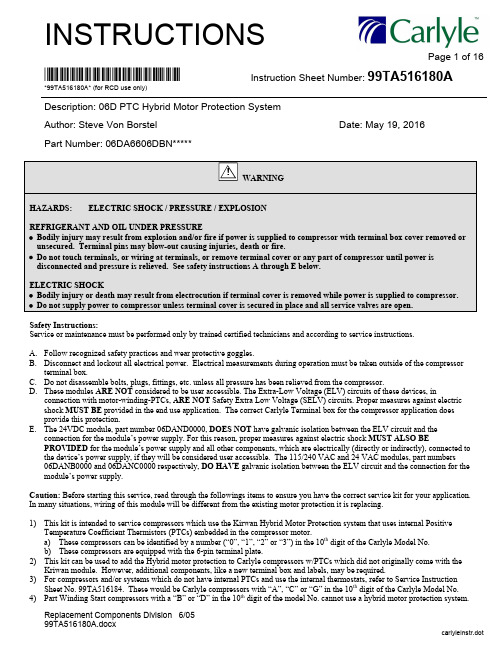
INSTRUCTIONSPage 1 of 16Replacement Components Division 6/0599TA516180A.docxcarlyleinstr.dot*99TA516180A* Instruction Sheet Number: 99TA516180A*99TA516180A* (for RCD use only)Description: 06D PTC Hybrid Motor Protection SystemAuthor: Steve Von BorstelDate: May 19, 2016Part Number: 06DA6606DBN*****WARNINGHAZARDS: ELECTRIC SHOCK / PRESSURE / EXPLOSIONREFRIGERANT AND OIL UNDER PRESSURE∙ Bodily injury may result from explosion and/or fire if power is supplied to compressor with terminal box cover removed or unsecured. Terminal pins may blow-out causing injuries, death or fire.∙ Do not touch terminals, or wiring at terminals, or remove terminal cover or any part of compressor until power is disconnected and pressure is relieved. See safety instructions A through E below.ELECTRIC SHOCK∙ Bodily injury or death may result from electrocution if terminal cover is removed while power is supplied to compressor. ∙ Do not supply power to compressor unless terminal cover is secured in place and all service valves are open.Safety Instructions:Service or maintenance must be performed only by trained certified technicians and according to service instructions.A. Follow recognized safety practices and wear protective goggles.B. Disconnect and lockout all electrical power. Electrical measurements during operation must be taken outside of the compressorterminal box.C. Do not disassemble bolts, plugs, fittings, etc. unless all pressure has been relieved from the compressor.D. These modules ARE NOT considered to be user accessible. The Extra-Low Voltage (ELV) circuits of these devices, inconnection with motor-winding-PTCs, ARE NOT Safety Extra Low Voltage (SELV) circuits. Proper measures against electric shock MUST BE provided in the end use application. The correct Carlyle Terminal box for the compressor application does provide this protection.E. The 24VDC module, part number 06DAND0000, DOES NOT have galvanic isolation between the ELV circuit and theconnection for the module’s power supply. For this reason, proper measures against electric shock MUST ALSO BEPROVIDED for the module’s power supply and all other components, which are electrically (directly or indirectly), connected to the device’s power supply, if they will be considered user accessible. The 115/240 VAC and 24 VAC modules, part numbers 06DANB0000 and 06DANC0000 respectively, DO HAVE galvanic isolation between the ELV circuit and the connection for the module’s power supply.Caution: Before starting this service, read through the followings items to ensure you have the correct service kit for your application. In many situations, wiring of this module will be different from the existing motor protection it is replacing.1) This kit is intended to service compressors which use the Kirwan Hybrid Motor Protection system that uses internal PositiveTemperature Coefficient Thermistors (PTCs) embedded in the compressor motor.a) These compressors can be identified by a number (“0”, “1”, “2” or “3”) in the 10th digit of the Carlyle Model No. b) These compressors are equipped with the 6-pin terminal plate.2) This kit can be used to add the Hybrid motor protection to Carlyle compressors w/PTCs which did not originally come with theKriwan module. However, additional components, like a new terminal box and labels, may be required.3) For compressors and/or systems which do not have internal PTCs and use the internal thermostats, refer to Service InstructionSheet No. 99TA516184. These would be Carlyle compressors with “A”, “C” or “G” in the 10th digit of the Carlyle Model No. 4) Part Winding Start compressors with a “B” or “D” in the 10th digit of the model No. cannot use a hybrid motor protection system.!5)Single Phase compressors refer to instructions 99TA516185.6)There are three different control voltages that are available for these protection modules. The control voltage is coded into the KitNo. and the Module No.Control Voltage 10th Digit Comp’r Model No. Kit No. (12th digit) Module No. (6th digit)110 -220 VAC 06DF3132A13650 06DA6606DBN B****06DBN B****24 VAC 06DF3132A2365006DA6606DBN C****06DBN C****24 VDC 06DF3132A3365006DA6606DBN D****06DBN D****7)Each kit has been preprogrammed to trip at the required Maximum Continuous Current (MCC) value. The MCC value is codedinto the last 4 digits of the service kit number and the part number of the module. The number shown in the last four digits represents the MCC value in tenths of an Amp:Example: Required MCC Kit No. (13th – 16th digit) Module No. (7th – 10th digit)13.5 Amps 06DA6606DBNB013506DBNB013544.0 Amps 06DA6606DBNC044006DBNC044020.9 Amps 06DA6606DBNC020906DBNC0209Appendix II is a list of the Carlyle Compressor Models that are supported by these kits. Verify that the MCC of the module corresponds to the compressor being serviced. If any of this information is not correct for the unit being serviced, do not use this kit. Contact RC or Carlyle Compressor for assistance.1 This kitcontains:No. QTY. Part No. Kit No. Description1 1 06DA509598 ALL BRACKET2 106DANB0000 06DA6606DBNB**** 110-120 VAC MODULE06DANC0000 06DA6606DBNC**** 24 VAC MODULE06DAND0000 06DA6606DBND**** 24 VDC MODULE3 1 06DA509599 ALL CURRENTTRANSFORMER4 2 AL56JA126 ALL #6 SCREW FOR CT (NOT SHOWN)5 2 AK87JY078 ALL #6 SCREW FOR MODULE (NOT SHOWN)6 2 99WZ0830QA201214 ALL WIREASSY7 1 06DA509601 ALL MCC PROGRAMMING LABEL8 1 06DA409610 ALL HARDWARE KIT (NOT SHOWN)9 1 06DA509602 ALL WIRING LABEL (NOT SHOWN)123672Verify that kit received is suitable for the compressor and system being serviced. First, make sure the module is intended for Carlyle 06D compressor which is fitted with internal PTCs.3Verify required control voltage of the module is correct for the system/unit supply. If thecompressor was originally shipped with the hybrid motor protection arrangement, it will be reflected in the 10th digit of the Carlyle Model No. with a “1”, “2” or “3”. If the 10th digitcontains a “0” (zero), the compressor was originally shipped without a motor protectionsystem or may have been a service compressor.Control Voltage 10th Digit Comp’r Model No. Kit No. (12th digit) Module No. (6th digit)110 -220 VAC 06DF3132A13650 06DA6606DBS B****06DBN B****24 VAC 06DF3132A2365006DA6606DBS C****06DBN C****24 VDC 06DF3132A3365006DA6606DBS D****06DBN D****TBD 06DF3132A03650∙Verify that the system being service is intended touse the hybrid motor protection system.∙Verify control voltage requirements of the kit matchsystem being serviced or retrofitted.∙Review Steps 14-17 for additional considerations Module – Front Label6 Pin Terminal Plate 06D Comp’rs 10th Digit Contains “0”, “1”, “2” or “3”06C Comp’rs 5th Digit Contains a LetterModule – Back Label4Verify that the MCC value of the new kit and module matches the required value shown in Appendix I and the label on the module being replaced.5Make sure the system and compressor has been properly locked-out and tagged (LOTO) before proceeding with any work.6Remove the terminal box cover. If the compressor was originally fitted with hybrid motor protection system, the terminal box and wiring should resemble the Figure below:MODULECTCOMPRESSOR TERMINAL PLATE7 There are four sets of electrical connections that must be removed and then reconnected on the new module.A)Control Power to the module (Terminals “L” & “N” on the module)B)Module connections for the control circuit (Terminal “11” & “14” on the module)C)Power Lead that is monitored by the CT (Current Transformer) @ the terminal plateD)PTC connections @ the terminal plate (Terminals “7” & “9” on the compressor)8 Disconnect these connections at the locations shown above. If required, mark the wires for the module power and the control circuit connections so they are not mixed or switched during assembly.ABCDPOWER LEADTHROUGH CT9 Remove the screws which hold the entire control module assembly to the terminal box. Two on the side and one inside the box.10 Double check that the labels on the control module being replaced and the new control module are the same.11 Re-install the new module assembly and affix to the terminal box. The screws on the side of the terminal box (#10-16 Thread Forming) are torque to 12-24 in-lbs and the screw in the bottom (#10-32 UNC) is torque to 36-60 in-lbs.12Re-connect the electrical connections removed in Step 8.Below are the associated torque limits with thoseconnections. Refer to the picture in Step 7. Make surethe power connection to the compressor goes throughthe CT and that the components for the compressorterminal pin connection are arranged correctly as shown.The Dished Retainer must be oriented so it extendsthrough the Phase Barrier and the terminal sits on top.CONNECTION TORQUEIN-LBS A) CONTROL POWER TO MODULE9-11 IN-LBSB) CONTROL CIRCUIT TO MODULEC) POWER CONNECTION TO TERMINAL PIN18-30 IN-LBSD) PTC WIRES FROM MODULE TO TERMINAL PINS13 Make sure correct label(s) are installed on the terminal box cover. The labels should be the same as the ones shipped with the kit. If not, install the new labels on the terminal box cover. Torque the terminal box cover screws to 12-24 in-lbs.Retrofitting the PTC Hybrid Motor Protection System to a Carlyle PTC compressor thatcurrently does not use the system.14 If this hybrid motor protection is beingretrofitted to a 6-pin Carlyle compressorwith PTC for the first time, make sure thecompressor has a “Large Folded” terminalbox (06DA407764 for gray)Note:The large folded box required to fit thismotor protection system is not rated foroutdoor use.DISHED RETAINERUP15 Two and four cylinder compressors will require a spacer (06DA509606) under the terminal box to accommodate the large folded box. This spacer is included in the service kit parts bag sent out with each service module. Note: The longer #10-32 screws (1/2” lg) must be used when the spacer is used under the terminal box. 3/8” long screws are used w/o the spacer.SPACER16 Ensure one of the power leads is long enough to be routed through the CT. For this module, it does not matter which power lead goes through the CT. The power lead for either #1, #2 or #3 can be used. Note: only one lead should go through the CT and only once as shown.17 Control voltage will have to be supplied in accordance with the module selected. Power consumption is 3 VA.End.POWER LEADTHROUGH CTAPPENDIX I: TOOLS FOR 06D HYBRID MOTOR PROTECTION SERVICEREVISION RECORDDATEREV.DESCRIPTIONCARLYLE REF. FILE NAME11/10/15 --- INITIAL RELEASE99TA516180_PTC_Hybrid_Mtr_Protech.docx 5/19/16 AADDED 24 VDC MODELS & ASSOCIATED WARNINGS99TA516180A_PTC_Hybrid_Mtr_Protech.docxTOOLTOOL NUMBER SUPPLIER OPERATION S T E P (s)NOTES5/16” NUT DRIVER00941972000P CRAFTSMAN REMOVING & INSTALLING: ∙ TERMINAL BOX COVER ∙ MTR PROTECTION ASSY 6 9 1113#2 PHILLIPS OR FLAT BLADE SCREW DRIVERAWP2X125 FACOM REMOVING/INSTALLING WIRE CONNECTIONS ON MODULE 8 12FLAT BLADE SCREW DRIVER AW10X200 FACOM REMOVING/INSTALLING TERMINAL BARREL NUTS8 12TO FIT .064/.075”SLOTAppendix II – Compressor Model Cross Reference to Module Kit No.Appendix II – Compressor Model Cross Reference to Module Kit No. Cont.Appendix II – Compressor Model Cross Reference to Module Kit No. Cont.Appendix II – Compressor Model Cross Reference to Module Kit No. Cont.Appendix II – Compressor Model Cross Reference to Module Kit No. Cont.。
京瓷1020操作说明书范文

京瓷1020操作说明书范文FS-1020MFP本操作手册旨在帮助您正确操作机器、执行日常保养以及在需要时采取简单的故障排除措施,以便可以始终使用处于良好工作状态的机器。
附带的手册本机附带以下手册。
请在需要时参阅这些文件。
快速安装手册安全指南安全指南FS-1020MFP/FS-1025MFP/FS-1120MFP/FS-1125MFP/1220MFP/FS-1320MFP/FS-1325MFP)ProductLibrary光盘操作手册(本手册)KYOCERAClientTool用户指南PrinterDriver用户指南KYOCERANetViewer用户指南介绍机器的安装步骤。
提供在安装和使用机器时用到的安全和注意信息。
使用本机前,请务必阅读该指南。
介绍机器安装空间、小心区域和其他信息。
使用本机前,请务必阅读该指南。
介绍如何装入纸张、基本复印、打印和扫描操作以及故障排除。
介绍如何使用KYOCERAClientTool。
KYOCERAClientTool是一个安装在计算机中让您用来配置机器设定的软件程序。
介绍如何安装打印驱动程序和使用打印机功能。
介绍如何通过KYOCERANetViewer监控网络打印系统。
目录机器部件............................................................. ............................................................... ................................................1-1前部机器组件............................................................. ............................................................... ........................................1-2后部机器组件............................................................. ............................................................... ........................................1-3操作面板............................................................. ............................................................... ................................................1-4准备工作............................................................. ............................................................... ................................................2-1连接............................................................. ............................................................... ........................................................2-2装纸............................................................. ............................................................... ........................................................2-4装入原............................................................... ..............................................2-16安装和卸载驱动程序和实用程序............................................................. ............................................................... ......2-17机器设定............................................................. ............................................................... ..............................................2-22配置............................................................. ............................................................... ......................................................2-36打印状态页............................................................. ............................................................... ..........................................2-42复印............................................................. ............................................................... ........................................................3-1基本操作............................................................. ............................................................... ................................................3-2手动双面............................................................. ............................................................... ................................................3-3使用程序............................................................. ............................................................... ................................................3-5复印功能............................................................. ............................................................... ................................................3-5身份证复............................................................... ............................................3-6打印............................................................. ............................................................... ........................................................4-1从应用程序软件进行打印............................................................. ............................................................... ....................4-2关于G某驱动程序............................................................. ............................................................... ................................4-2手动双面............................................................. ............................................................... ................................................4-3打印文件夹............................................................. ............................................................... ............................................4-5更改初始PrinterDriver设定(Window7).................................................... ..........................................................4-6扫描............................................................. ............................................................... ........................................................5-1自动路由扫描............................................................. ............................................................... ........................................5-2使用程序............................................................. ............................................................... ................................................5-3快速扫描(扫描为PDF格式/扫描至电子邮件/扫描至文件...............5-4使用TWAIN/WIA扫描............................................................. ............................................................... ......................5-5保养............................................................. ............................................................... ........................................................6-1一般信息............................................................. ............................................................... ................................................6-2墨粉盒更换............................................................. ............................................................... ............................................6-2更换保养组件............................................................. ............................................................... ........................................6-5清洁机器............................................................. ............................................................... ................................................6-5维修保养菜单............................................................. ............................................................... ........................................6-7长期不使用机器和移动机器............................................................. ............................................................... ................6-8故障排除............................................................. ............................................................... ................................................7-1解除故障............................................................. ...............................................................................................................7-2错误信息............................................................. ............................................................... ................................................7-7清除卡纸............................................................. ............................................................... ................................................7-9附录............................................................. ............................................................... ........................................................8-1规格............................................................. ............................................................... ........................................................8-22345678索引............................................................. .............................索引-1ii法律和法律和安全信息声明本手册内容若有变更,恕不另行通知。
惠普 LaserJet Pro MFP M25-M27 用户指南说明书

克罗韦尔 PanelView Plus 6 Compact 终端 说明书

新信息和更新信息
本手册中包含新增信息和更新信息。
变更摘要
下表包含了本版本所做的变更。
主题 更新了表 7 中的交流电压和频率。 更新了 2711PCT10C4D8 终端。从最新系列 B 终端中移除了 迷你 USB 端口 (B 型 )。 在整本用户手册中,移除了系列 B 2711PCT10C4D8 终端的 数据和图纸中的迷你 USB 端口 (B 型 )。
Allen-Bradley、 Rockwell Software、 Rockwell Automation、 PanelView、 FactoryTalk、 RSLinx、 CompactLogix、 ControlLogix、 SLC、 MicroLogix、 PLC-5 和 RSView 是罗克韦尔自动化有限公司的商标。 不属于罗克韦尔自动化的商标是其各自所属公司的财产。
用户手册
PanelView Plus 6 Compact 终端
产品目录号 2711PC-K4M20D8、 2711PC-B4C20D8、 2711PC-B4C20D8-LR、 2711PC-T6M20D8、 2711PC-T6C20D8、 2711PC-T10C4D8
重要用户须知
在安装、配置、操作或维护设备之前,请仔细阅读本文档及 “ 其他资源 ” 部分列出的文档,了解设备的安 装、配置和操作信息。除了所有适用的条例、法律和标准的要求之外,用户还必须熟悉安装和接线说明。
注意:标识可能会导致人员伤亡、财产损坏或经济损失的操作或情况的信息。注意符号 可帮助您确定危险情况,避免发生危险,并了解可能的后果。
重要信息 标识对成功应用和了解产品有重要作用的信息。
标签可能位于设备上或设备内,用于提供特定警示。
电击危险:位于设备 ( 例如,驱动器或电机 ) 表面或内部的标签,提醒人们可能存在危险 电压。
- 1、下载文档前请自行甄别文档内容的完整性,平台不提供额外的编辑、内容补充、找答案等附加服务。
- 2、"仅部分预览"的文档,不可在线预览部分如存在完整性等问题,可反馈申请退款(可完整预览的文档不适用该条件!)。
- 3、如文档侵犯您的权益,请联系客服反馈,我们会尽快为您处理(人工客服工作时间:9:00-18:30)。
CONTENTSSection PageIMPORTANT SAFEGUARDS AND WARNINGS (3)DESCRIPTION (4)MODELS (4)INSTALLATION (4)WINDOW WIPER KIT MODIFICATION (4)WINDOW WIPER KIT INSTALLATION (7)MAINTENANCE (15)SERVICE MANUAL (15)WARRANTY AND RETURN INFORMATION (16)LIST OF ILLUSTRATIONSFigure Page 1Wiper Modification (4)2Wiper Circuit Board Component Locations (5)3Circuit Side of Wiper Board (5)4Wiper Driver Schematic (6)5Wiper Drive Shaft Installation (8)6Wiper Shaft/Wiper Assembly Connector (8)7Wiper Circuit Board Component Locations (8)8Component Locations for Optional Circuit Board (O/I-PCB) (11)9Wiper On/Off Connection (11)10Exploded Assembly Diagram for Window Wiper (13)LIST OF TABLESTable Page A24 VAC Wiring Distances (12)B Exploded Assembly Parts List for Window Wiper (14)IMPORTANT SAFEGUARDS AND WARNINGSPrior to installation and use of this product, the following WARNINGS should be observed.1.Installation and servicing should only be done by qualified service personnel and con-form to all local codes.2.Unless the unit is specifically marked as a NEMA Type 3, 3R, 3S, 4, 4X ,6 or 6P enclo-sure, it is designed for indoor use only and it must not be installed where exposed to rain and moisture.3.Only use replacement parts recommended by Pelco.The product and/or manual may bear the following marks:Please thoroughly familiarize yourself with the information in this manual prior to installationand operation.This symbol indicates that dangerous volt-age constituting a risk of electric shock is present within this unit.This symbol indicates that there are impor-tant operating and maintenance instructions in the literature accompanying this unit.C A U T I O N :RISK OF ELECTRIC SHOCK.DO NOT OPEN.DESCRIPTIONWindow wiper kits in the WW57 Series are for installation in the EH5700 Series andEH5700L Legacy® Series environmental enclosures.MODELSWW5723-1Window wiper kit for EH5723/EH5723L, 120 VAC, 15 wattsWW5723-2Window wiper kit for EH5723/EH5723L, 24 VAC, 15 watts (CE)WW5723-3Window wiper kit for EH5723/EH5723L, 230 VAC, 15 watts (CE)WW5729-1Window wiper kit for EH5729/EH5729L, 120 VAC, 15 wattsWW5729-2Window wiper kit for EH5729/EH5729L, 24 VAC, 15 watts (CE)WW5729-3Window wiper kit for EH5729/EH5729L, 230 VAC, 15 watts (CE) INSTALLATIONWindow wiper kits in the WW57 Series are designed to operate with an AC voltage to turnon the wiper. However, the kits must be modified to use +5 to +10 VDC to turn on the wiperwhen the kits are used with Pelco’s receivers.If you are going to use a Pelco receiver, proceed to the Window Wiper Kit Modification sec-tion.If you are going to use equipment that provides AC power to control the wiper, proceed tothe Window Wiper Kit Installation section.WINDOW WIPER KIT MODIFICATIONModify your wiper kit if it is to be operated from any of the following Pelco receivers:CX9000 SeriesWX8000 SeriesLRD41 SeriesERD97P21-U with the ERD97P-AUX option boardThis modification only changes the voltage that is required to turn on the wiper. The wipermotor still requires AC voltage (refer to Figure 1).To modify a kit:1.Remove the circuit board cover from the wiper motor/control assembly and remove thecircuit board (PCB9000275 Rev. E). Refer to Figure 10 for parts locations.Refer to Figure 2 for steps 2-5.Figure 1. Wiper ModificationJP1ADDWIREWiper Circuit Board Component LocationsFigure 2.2.Remove diodes D1 through D6.3.Replace resistor R2 with a 1/4-watt 470-ohm resistor.4.Remove capacitor C3.5.Connect an 18-inch (45.72 cm) length of 22-gauge green wire to the hole in the circuitboard for the anode of D3.6.Turn the circuit board over and cut the trace as shown in Figure 3.Figure 4 shows schematically the changes that were made in steps 2-7.7.Reinstall the circuit board in the wiper motor/control assembly and reconnect the wir-ing. Refer to Figure 7.Proceed to the Window Wiper Kit Installation section.J P 6D E L A Y O N D E L A Y O F F1–22–3F i g u r e 4. W i p e r D r i v e r S c h e m a t i cWINDOW WIPER KIT INSTALLATIONFor the following instructions, refer to Figure 10, if necessary. Table B lists the parts shownin Figure 10.1.Turn off power to the enclosure.2.Unlatch and raise the enclosure lid. The gas spring will hold the lid in place when it isfully opened.3.Remove the camera and sled.4.EH5723/EH5723L and EH5729/EH5729L Models Only - Remove the ventgrill inside the enclosure at the rear of the unit.5.EH5723-1, -2, -3/EH5723L-1, -2, -3 Models, and EH5729-1, -2, -3/EH5729L-1, -2, -3 Models Onlya.Unplug the electrical connector on the fan.b.Remove the three screws that secure the fan plate and fan to the enclosure.c.Remove the fan plate and fan.d.Remove the fan from the fan plate.e.Attach the fan to the fan plate of the window wiper assembly in the same orienta-tion that it was attached to the original fan plate.6.Refer to Figure 5 and insert the wiper shaft into the green bushing on the fan plate ofthe wiper motor/control assembly.7.Insert the motor/control assembly into the enclosure and attach the assembly to theenclosure with the hardware that is supplied:a.Slip the blue, white, and black wiper wires into the slot at the bottom of the fanplate so that the white plug is on the opposite side of the fan plate from the wipercircuit board housing.b.On all models except the EH5723 and EH5729, remove the screws on the sidesof the circuit board in the enclosure so that the circuit board can be moved out ofthe way to install the wiper motor/control assembly.c.Place the assembly into the enclosure with the wiper circuit board housing facingtoward the rear of the enclosure and the fan plate against the camera sled track.d.Hook the rear of the circuit board mounting over the screw installed at the top ofthe enclosure’s rear panel. Secure the circuit board mounting to the enclosurewith the acorn nut.e.Attach the bottom right and bottom left sides of the fan plate to the camera sledtrack with screws and lock washers.f.On all models except the EH5723 and EH5729, reinstall the circuit board.8.Reconnect the electrical connector to the fan.9.Remove the latch on the side of the enclosure where the wiper shaft is located.10.Slide the support bracket onto the wiper shaft. Using the longer screws supplied in thewiper kit, attach the latch and support bracket to the enclosure.11.Slide the flange bearing over the bearing pin as shown in Figure 5, and slide the camtrack over the flange bearing. Only the tautness of the drive shaft holds the flangebearing in place.12.Refer to Figure 6 and slip the flex coupler over the drive shaft.13.Remove the hole plug from the wiper shaft hole in the front of the enclosure.14.From the outside of the enclosure, install the green bushing into the wiper shaft hole.Figure 7. Wiper Circuit Board Component Locations15.Remove the two screws on the bottom of the enclosure under the window and installthe wiper assembly with two Allen cap screws that are supplied in the parts bag. Make sure the shaft of the wiper arm goes through the green bushing on the front of the en-closure.16.Looking at the front of the enclosure from the outside, position the wiper blade so thatit is on the left side of the window as you look at it.17.Slide the flex coupler over the wiper arm shaft and tighten the two screws in the cou-pler to secure it to the drive shaft and the wiper arm shaft.18.Remove the cover over the circuit board on the wiper motor/control assembly.19.Refer to Figure 7 and set either of the following two options:a.The time between wiper strokes can be adjusted between 3 and 10 seconds by rotating the potentiometer R8. Turn the adjustment clockwise to increase the time.The potentiometer only makes one revolution.or b.The wiper can be set to operate continuously by placing the delay jumper at JP6in the OFF position.20.Verify that jumpers JP1 through JP5 are set for the correct input voltage.If you modified the circuit board, place JPI in the 1–2 position. This will route the DC voltage from the receiver to the on/off circuit of the wiper. Never place the jumper in the 2–3 position or the wiper will not work.21.Replace the cover over the circuit board on the wiper motor/control assembly.22.If you modified the circuit board, connect the green wire from the anode of D3 to eitherof the following:•If your enclosure has the O/I-PCB circuit board (PCB9000276), connect the wire to the LENS COM connector (refer to Figure 8).•If your enclosure does not have the circuit board, connect the wire to the LENS COM connector on your pan/tilt unit or receiver.23.EH5723 and EH5729 Models Only – Wire the wiper assembly to power as fol-lows:Black wire AC HI White wire AC NTBlue wireWiper on/off controlIf you modified the circuit board, wire the wiper on/off control to an auxiliary output on the receiver.All window wiper assemblies use 15 watts of power. If you are using 24 VAC, refer to Table A to determine the size of wire to use.24.All Models Except the EH5723 and EH5729 – Wire the wiper assembly topower as follows:a.Remove the plastic cover from the power supply section of the circuit board in front of the fan plate.b.Connect the plug from the wiper assembly into the W/W socket on the circuit board.c.Wire the wiper on/off control.If you modified the circuit board, wire the wiper on/off control to an auxiliary out-put on the receiver.WARNING: If youuse an AC control,AC high to turn onthe wiper must come from the same circuit that provides power to the wiper. This is because the wiper and the on/off control share the same AC neutral. Refer to Figure 9. This will preventdamage to the wiper.If you are installing the wiper kit in a Legacy enclosure, power for the wiper issupplied through the 37-pin connector on the pan/tilt unit as follows:AC High Pin 15AC Neutral Pin 16Wiper On/Off Control Pin 25If you are installing the wiper kit in a non-Legacy unit, power for the wiper is sup-plied as follows:AC High Pin 1 of TB2 on the O/I-PCB circuit board (refer to Figure 8)AC Neutral Pin 2 of TB2 on the O/I-PCB circuit boardWiper On/Off Control Pin 1 of TB3 on the O/I-PCB circuit boardPins 15 and 16 on Legacy enclosures and pins 1 and 2 of TB2 on non-Legacyenclosures also provide power for other enclosure accessories, such as the fanand heaters. Make sure that this wiring can handle the additional power for thewiper. All window wiper assemblies use 15 watts of power.d.Replace the plastic cover over the power supply on the circuit board.25.Reinstall the camera and sled.26.Close the enclosure lid.27.Turn on power to the enclosure.Figure 8. Component Locations for Optional Circuit Board (O/I-PCB)Figure 9. Wiper On/Off ConnectionWire GaugeM a x i m u m d i s t a n c e f r o m t r a n s f o r m e r t o l o a dTable A. 24 VAC Wiring DistancesThe following are the recommended maximum distances for 24 VAC applications and are calculated with a 10-percent voltage drop. (Ten percent is generally the maximum allowable voltage drop for AC-powered devices.)20181614121010283451716114218112880(86)(137)(218)(348)(551)(877)201412253585719051440(42)(68)(109)(174)(275)(438)3094150238380603960(28)(45)(72)(115)(183)(292)4070112179285452720(21)(34)(54)(86)(137)(219)505690143228362576(17)(27)(43)(69)(110)(175)604775119190301480(14)(22)(36)(57)(91)(146)704064102163258411(12)(19)(31)(49)(78)(125)80355689142226360(10)(17)(27)(43)(68)(109)90315079126201320(9)(15)(24)(38)(61)(97)100284571114181288(8)(13)(21)(34)(55)(87)110254165103164261(7)(12)(19)(31)(49)(79)12023375995150240(7)(11)(17)(28)(45)(73)13021345587139221(6)(10)(16)(26)(42)(67)14020325181129205(6)(9)(15)(24)(39)(62)15018304776120192(5)(9)(14)(23)(36)(58)16017284471113180(5)(8)(13)(21)(34)(54)17016264267106169(4)(7)(12)(20)(32)(51)18015253963100160(4)(7)(11)(19)(30)(48)1901423376095151(4)(7)(11)(18)(28)(46)2001422355790144(4)(6)(10)(17)(27)(43)T o t a l v A c o n s u m e dEXAMPLE: An enclosurethat requires 80 vA and is installed 35 feet (10 m) from the transformer would require a minimum wire gauge of 20 AWG.NOTE: Distances arecalculated in feet; values in parentheses are meters.Figure 10. Exploded Assembly Diagram for Window WiperTable B. Exploded Assembly Parts List for Window WiperItem Qty Description Part Number11Cam Assembly WW57001000ASSY 21Wiper Arm Assembly MF00-5701-01631Wiper Shaft (EH5729 Series)MF00-5701-015 1Wiper Shaft (EH5723 Series)MF00-5701-02941Wiper Driver Circuit Board Mount WW57004013COMP 51Wiper Motor57001001261Wiper Driver Circuit Board Cover WW57004014COMP 71Flex Coupling57001001481Fan Plate MF00-5701-01091Bronze Bearing Flange776003101Wiper Driver Circuit Board PCB9000275ASSY 1125/32 Hex 3/16 x 2-56 Standoff SPA8300121Switch Actuator SWlJS2211Switch SWl1SM1131Transformer (-1, -3 models)TRF21240.70.7CM 142Teflon Bearing Flange WW550010001153Wiper Blade (by the inch)WW570010050161Support Bracket MF01-5700-028171Switch Shield (not shown)MF01-5700-033A1Grommet GRO2170B8Nylon Washer #6ZH131X361X62ND2Hex Nut, 2-56ZH2-56NUTSHE2Screw, 2-56 x 3/4-inch, Pan Head, Phillips ZH2-56X.750SPSF4Internal Tooth Lock Washer, #2ZH2LWSISH3Screw, 4-40 x 1/4-inch, Pan Head, Phillips ZH4-40X.250SPPI5Internal Tooth Lock Washer, #4ZH4LWSISJ11Cap Screw, 6-32 x 3/8-inch, Allen Socket Head ZH6-32X.375CSK2Cap Screw, 4-40 x 3/8-inch, Allen Socket Head ZH4-40X.375CSL1Nut, 6-32, Acorn ZH6-32NUTCAM2Hex Nut, 6-32 (-1, -3 models)ZH6-32NUTSHN12Internal Tooth Lock Washer, #6ZH6LWSISMAINTENANCEAs necessary, clean the window with a mild non-abrasive detergent in water and a soft clothto maintain picture clarity.To order replacement wiper blades, use the part number WW570010050 (3 inches).SERVICE MANUALIf you need to service the wiper assembly, obtain a service manual in one of the followingways:•Go to Pelco’s web site at ftp:// and find service manual C1431SM.PDF.•Contact Pelco’s Literature Department and request service manual C1431SM.®Pelco and the Pelco logo are registered trademarks of Pelco.© Copyright 1999, Pelco. All rights reserved.REVISION HISTORYManual #Date Comments C1432M 10/95Original manual.C1432M-A 4/96Revision A. Revised installation instructions.C1432M-B 3/98Added Section 3.1. Moved service information to manual C1431SM.C1432M-C11/99Revised Figure 10 to show new support bracket and modified wiper shafts. Revised installation instructions to add support bracket.PRODUCT WARRANTY AND RETURN INFORMATIONWARRANTYPelco will repair or replace, without charge, any merchandise proved defective in material or workmanship for a period of one year after the date of shipment. Exceptions to this warranty are as noted below:•Five years on FT/FR8000 Series fiber optic products.•Three years on Genex ® Series products (multiplexers, server, and keyboard).•Three years on Camclosure ® and fixed camera models, except the CC3701H-2,CC3701H-2X, CC3751H-2, CC3651H-2X, MC3651H-2, and MC3651H-2X camera models,which have a five-year warranty.•Two years on standard motorized or fixed focal length lenses.•Two years on Legacy ®, CM6700/CM6800/CM9700 Series matrix, and DF5/DF8 Series fixed dome products.•Two years on Spectra ®, Esprit ®, ExSite ™, and PS20 scanners, including when used in continuous motion applications.•Two years on Esprit ® and WW5700 Series window wiper (excluding wiper blades).•Eighteen months on DX Series digital video recorders, NVR300 Series network video recorders, and Endura ™ Series distributed network-based video products.•One year (except video heads) on video cassette recorders (VCRs). Video heads will be covered for a period of six months.•Six months on all pan and tilts, scanners or preset lenses used in continuous motion applications (that is, preset scan, tour and auto scan modes).Pelco will warrant all replacement parts and repairs for 90 days from the date of Pelco shipment. All goods requiring warranty repair shall be sent freight prepaid to Pelco, Clovis,California. Repairs made necessary by reason of misuse, alteration, normal wear, or accident are not covered under this warranty.Pelco assumes no risk and shall be subject to no liability for damages or loss resulting from the specific use or application made of the Products. Pelco’s liability for any claim, whether based on breach of contract, negligence, infringement of any rights of any party or product liability, relating to the Products shall not exceed the price paid by the Dealer to Pelco for such Products. In no event will Pelco be liable for any special, incidental or consequential damages (including loss of use, loss of profit and claims of third parties) however caused,whether by the negligence of Pelco or otherwise.The above warranty provides the Dealer with specific legal rights. The Dealer may also have additional rights, which are subject to variation from state to state.If a warranty repair is required, the Dealer must contact Pelco at (800) 289-9100 or (559) 292-1981 to obtain a Repair Authorization number (RA), and provide the following information:1.Model and serial number2.Date of shipment, P .O. number, Sales Order number, or Pelco invoice number3.Details of the defect or problemIf there is a dispute regarding the warranty of a product which does not fall under the warranty conditions stated above, please include a written explanation with the product when returned.Method of return shipment shall be the same or equal to the method by which the item was received by Pelco.RETURNSIn order to expedite parts returned to the factory for repair or credit, please call the factory at (800) 289-9100 or (559) 292-1981 to obtain an authorization number (CA number if returned for credit, and RA number if returned for repair).All merchandise returned for credit may be subject to a 20% restocking and refurbishing charge.Goods returned for repair or credit should be clearly identified with the assigned CA or RA number and freight should be prepaid. Ship to the appropriate address below.If you are located within the continental U.S., Alaska, Hawaii or Puerto Rico, send goods to:Service Department Pelco3500 Pelco WayClovis, CA 93612-5699If you are located outside the continental U.S., Alaska, Hawaii or Puerto Rico and are instructed to return goods to the USA, you may do one of the following:If the goods are to be sent by a COURIER SERVICE, send the goods to:Pelco3500 Pelco WayClovis, CA 93612-5699 USA If the goods are to be sent by a FREIGHT FORWARDER, send the goods to:Pelco c/o Expeditors 473 Eccles AvenueSouth San Francisco, CA 94080 USA Phone: 650-737-1700Fax: 650-737-0933。