verilog-Chapter1
verilog语言参考目录说明
verilog语言参考目录说明目录一.关于 IEEE 1364 标准二.Verilog简介三.语法总结四.编写Verilog HDL源代码的标准五.设计流程Verilog 硬件描述语言参考手册(按英文字母顺序查找部分)Always 声明语句Assign 连续赋值声明语句Begin 声明语句Case 声明语句:Comment注释语句Defparam 定义参数声明语句Delay 时延Disable 禁止Errors 错误Event 事件Expression 表达式For 循环声明语句Force 强迫赋值Forever 声明语句Fork 声明语句Function 函数Function Call 函数调用Gate 门IF 条件声明语句Initial 声明语句Instantiation 实例引用Module 模块定义Name 名字Hierarchical Names 分级名字Upwards Name Referencing 向上索引名Net 线路连接Number 数Operators 运算符Parameter 参数PATHPULSE$ 路径脉冲参数Port 端口Procedural Assignment 过程赋值语句Procedural Continuous Assignment 过程连续赋值语句Programming Language Interface 编程语言接口Register 寄存器Repeat 重复执行语句Reserved Words 关键词Specify 指定的块延时Specparam 延时参数Statement 声明语句Strength 强度String 字符串Task 任务Task Enable 任务的启动Timing control 定时控制User Defined Primitive 用户自定义原语While 条件循环语句Compiler Directives 编译器指示Standard Compiler Directives 标准的编译器指示Non-Standard Compiler Directives 非标准编译器指示系统任务和函数 System task and function标准的系统任务和函数$display, $monitor, $strobe, $write 等$fopen 和$fclose$readmemb 和 $readmemh$timeformat[(Units,Precision,Suffix,MinFieldWidth)]; $printtimescale$stop$finish$time,$stime,和 $realtime$realtobits 和 $bitstoreal$rtoi 和 $itor随机数产生函数1)$random2)$dist_chi_square3)$dist_erlang4)$dist_exponential5)$dist_normal6)$dist_poisson7)$dist_t8)$dist_uniform指定块内的定时检查系统任务Specify Block Timing Checks1)$hold2)$nochange3)$period4)$recovery5)$setup6)$setuphold7)$skew8)$width记录数值变化的系统任务 Value Change Dump Tasks1)$dumpfile2)$dumpvars3)$dumpoff;4)$dumpon;5)$dumpall;6)$dumplimit( FileSize);7) $dumpflush;非标准的系统任务和函数$countdrivers$list$input$scope and $showscopes$key, $nokey, $log and $nolog$reset[$reset_count$reset_value$save(“FileName”);$incsave(“FileName”);$restart(“FileName”);$showvars[( NetOrRegister,...)];$getpattern( MemoryElement);$sreadmemb (Memory, StartAddr, FinishAddr, String, ...); $sreadmemh (Memory, StartAddr, FinishAddr, String, ...); $scale(DelayName); {Returns realtime}常用系统任务和函数的详细使用说明$display 和 $write$fopen and $fclose$monitor 等$readmemb 和 $readmemh$strobe$timeformat随机模型 Stochastic Modelling$q_initialize$q_add$q_remove$q_full$q_exam定时检查 Timing Checks$hold$nochange$period$recovery$setup$setuphold$skew$width记录数值变化的系统任务 Value Change Dump Tasks $dumpfile $dumpvars$dumpoff;$dumpon;$dumpall;$dumplimit$dumpflush;Command Line Options 命令行的可选项。
verilog教程

verilog教程Verilog是一种硬件描述语言(HDL),用于描述数字系统的行为和结构。
它是一种流行的HDL,广泛用于硬件设计和验证领域。
本教程将介绍Verilog的基本概念和语法,以帮助初学者入门。
一、Verilog的基本概念1.1 什么是VerilogVerilog是一种描述数字系统的语言,它可以用来描述硬件电路、验证设计的正确性以及进行电路仿真。
1.2 Verilog的应用领域Verilog广泛应用于硬件设计和验证领域,包括用于开发ASIC(应用特定集成电路)、FPGA(现场可编程门阵列)以及其他数字系统的设计。
1.3 Verilog的版本Verilog有多个版本,包括Verilog-1995、Verilog-2001以及最新的Verilog-2005、这些版本之间有一些语法和功能上的差异。
二、Verilog的语法结构2.1模块和端口在Verilog中,所有的电路描述都是由模块(module)组成的。
模块是电路的基本组成单元,可以看作是一个黑盒子,它接受一些输入,产生一些输出。
2.2信号声明在Verilog中,我们需要声明所有的输入和输出信号。
可以使用`input`和`output`关键字来声明这些信号。
2.3电路实现Verilog允许使用多种语句和结构来描述电路的行为和结构。
这些语句包括顺序语句、条件语句、循环语句以及层次结构。
2.4实例化模块在一个模块中,我们可以实例化其他的模块。
这样可以将一个大的电路拆分成多个小的模块,方便编写和测试。
三、Verilog的仿真和验证3.1静态验证Verilog语言本身提供了很多语法和语义层面的验证功能,对于语法和类型错误会有相应的提示。
3.2激励设计在进行电路验证时,我们需要为输入信号提供激励。
Verilog提供了一种称为`testbench`的特殊模块,用于生成输入信号并将其应用到待验证的电路中。
3.3波形仿真在Verilog中,我们可以使用仿真器来模拟电路的行为,并生成波形图来验证电路是否按预期工作。
Verilog的讲义52页PPT
0
0x
9
9.40ns
9
01
10
10.00ns 10
11
19
19.40ns 19
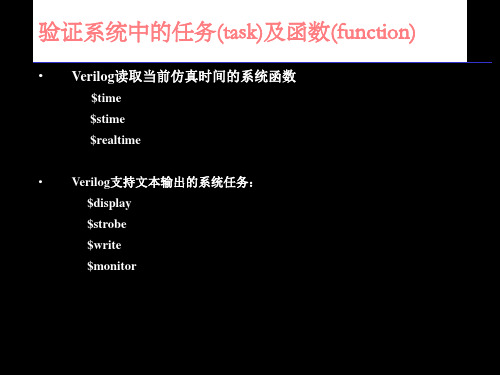
显示信号值 — $display
• $display输出参数列表中信号的当前值。 语法:$display([“ format_specifiers”,] <argument_ list>)
• $display输出时自动换行。
%m %t
hex octal decimal binary ASCII string strength module time
转义符
\t \n \\
\" \< 1-3 digit octal number> %0d
tab 换行 反斜杠 双引号 上述的ASCII表示 无前导0的十进制数
显示信号值—$write和$strobe
9.53ns
initial
10
01
begin
10 10.00ns 10
11
$display("time realtime20stime19\.t53ns
20
in1 \t o1 ");
10
$timeformat(-9, 2, "ns", 10);
$monitor("%d %t %d \t %b \t %b", $time, $realtime,
• $write与$display相同,不同的是不会自动换行。
$write($time, “%b \t %h \t %d \t %o \t”, sig1, sig2, sig3, sig4);
• $strobe与$display相同,不同的是在仿真时间前进之前的信号值。 而$display和$write立即显示信号值。也就是说$strobe显示稳定状态 信号值,而$display和$write可以显示信号的中间状态值。
Verilog HDL简明教程中文版
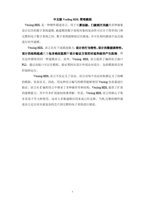
中文版Verilog HDL简明教程Verilog HDL是一种硬件描述语言,用于从算法级、门级到开关级的多种抽象设计层次的数字系统建模。
被建模的数字系统对象的复杂性可以介于简单的门和完整的电子数字系统之间。
数字系统能够按层次描述,并可在相同描述中显式地进行时序建模。
Verilog HDL 语言具有下述描述能力:设计的行为特性、设计的数据流特性、设计的结构组成以及包含响应监控和设计验证方面的时延和波形产生机制。
所有这些都使用同一种建模语言。
此外,Verilog HDL语言提供了编程语言接口PLI,通过该接口可以在模拟、验证期间从设计外部访问设计,包括模拟的具体控制和运行。
Verilog HDL语言不仅定义了语法,而且对每个语法结构都定义了清晰的模拟、仿真语义。
因此,用这种语言编写的模型能够使用Verilog仿真器进行验证。
语言从C编程语言中继承了多种操作符和结构。
Verilog HDL提供了扩展的建模能力,其中许多扩展最初很难理解。
但是,Verilog HDL语言的核心子集非常易于学习和使用,这对大多数建模应用来说已经足够。
当然,完整的硬件描述语言足以对从最复杂的芯片到完整的电子系统进行描述。
第1章简介Verilog HDL是一种硬件描述语言,用于从算法级、门级到开关级的多种抽象设计层次的数字系统建模。
被建模的数字系统对象的复杂性可以介于简单的门和完整的电子数字系统之间。
数字系统能够按层次描述,并可在相同描述中显式地进行时序建模。
Verilog HDL 语言具有下述描述能力:设计的行为特性、设计的数据流特性、设计的结构组成以及包含响应监控和设计验证方面的时延和波形产生机制。
所有这些都使用同一种建模语言。
此外,Verilog HDL语言提供了编程语言接口,通过该接口可以在模拟、验证期间从设计外部访问设计,包括模拟的具体控制和运行。
Verilog HDL语言不仅定义了语法,而且对每个语法结构都定义了清晰的模拟、仿真语义。
verilog教程

verilog教程当您开始学习Verilog时,以下是一些重要的基础知识和概念。
1. Verilog是一种硬件描述语言(HDL),用于描述和设计数字电路。
它可以用于模拟、合成和验证电路。
2. Verilog使用模块化的设计风格。
每个设计都由一个或多个模块组成,每个模块有自己的输入和输出。
3. 使用`module`关键字定义一个模块,并在其后给出模块的名称。
```verilogmodule my_module;// 模块主体endmodule```4. 模块内部包含用`input`和`output`声明的端口,用于与其他模块进行通信。
```verilogmodule my_module(input wire a,input wire b,output wire c);// 模块主体endmodule```5. `wire`关键字用于声明连接不同模块的导线。
可以将导线看作是用于传输数字信号的线。
6. 在模块主体中,可以使用`assign`关键字创建逻辑连接。
逻辑连接使用`=`运算符连接输入和输出。
```verilogmodule my_module(input wire a,input wire b,output wire c);assign c = a & b;endmodule```7. 除了逻辑连接外,可以在模块内部使用`always`块创建组合和时序逻辑。
```verilogmodule my_module(input wire a,input wire b,output wire c);reg d;always @(a or b)d = a | b;assign c = d;endmodule```8. Verilog还支持使用`if-else`语句,`case`语句和循环结构等常见的编程结构。
9. 为了模拟和验证设计,可以使用Verilog仿真工具,如ModelSim、VCS等。
第四章 Verilog基本语法(一)PPT教学课件

2020/12/11
玉溪师范学院
参数
➢ 参数是一个常量。用parameter定义一个标识符来代表 一个常量。参数经常用于定义时延和变量的宽度。
格式: parameter param1 = const_expr1,
param2 = const_expr2,
…,
paramN = const_exprN;
assign #XOR_DELAY S=A^B;
assign #AND_DELAY C=A&B;
endmodule
19
TOP HA
2020/12/11
玉溪师范学院
参数值的模块引用
module TOP3(NewA,NewB,NewS,NewC); input NewA, NewB; output NewS,NewC; HA #(5,2) Ha1 (NewA, NewB, NewS, NewC);ut
selb
26
2020/12/11
玉溪师范学院
reg型
寄存器是数据存储单元的抽象 reg型数据常用来表示always块内的指定信号,常代表触
发器 reg型数据用initial或者always块中指定信号 reg型数据的缺省值是x。可以被赋正值或者负值。当它作
为一个表达式中的操作数时候,作为无符号数。 reg数据类型定义格式为
2.0 ; -0.1等
科学记数法,例如:
235.1e2 等于23510.0
234_12e2
等于2341200.0
实数小数通过四舍五入被隐式地转换为最相近的整数。例如:
42.446, 42.45 转换为整数42
92.5, 92.699 转换为整数93
-5.62 转换为整数-6
verilog基本语法、模块写法
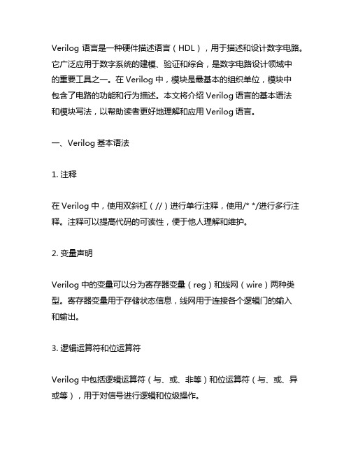
Verilog语言是一种硬件描述语言(HDL),用于描述和设计数字电路。
它广泛应用于数字系统的建模、验证和综合,是数字电路设计领域中的重要工具之一。
在Verilog中,模块是最基本的组织单位,模块中包含了电路的功能和行为描述。
本文将介绍Verilog语言的基本语法和模块写法,以帮助读者更好地理解和应用Verilog语言。
一、Verilog基本语法1. 注释在Verilog中,使用双斜杠(//)进行单行注释,使用/* */进行多行注释。
注释可以提高代码的可读性,便于他人理解和维护。
2. 变量声明Verilog中的变量可以分为寄存器变量(reg)和线网(wire)两种类型。
寄存器变量用于存储状态信息,线网用于连接各个逻辑门的输入和输出。
3. 逻辑运算符和位运算符Verilog中包括逻辑运算符(与、或、非等)和位运算符(与、或、异或等),用于对信号进行逻辑和位级操作。
4. 控制语句Verilog支持if-else语句、case语句等控制语句,用于根据不同条件执行不同的操作。
5. 模拟时钟在Verilog中,时钟是电路中的重要部分,通常使用时钟信号来同步各个元件的动作。
时钟可以通过周期性方波信号来模拟,使用$period 函数可以定义时钟的周期。
6. 仿真指令Verilog提供了多种仿真指令,用于初始化信号、设置仿真时间、输出波形图等操作,有助于仿真和调试电路。
二、模块写法1. 模块定义在Verilog中,一个模块包含了一组功能相关的硬件描述,可以看作是一个小型电路的抽象。
模块通过module关键字进行定义,其中包括模块名、输入输出端口声明等信息。
```verilogmodule adder(input wire [3:0] a,input wire [3:0] b,output reg [4:0] c);// 模块内部逻辑描述endmodule```2. 端口声明模块的端口包括输入端口(input)和输出端口(output),可以通过wire和reg进行声明。
verilog(1)
Z or z
High Impedance
0、1代表常见的布尔状态或者电平的状态 X常用于仿真中表示发生冲突或者错误,也可用于表示“don’t care” Z代表电路中的高阻状态 0、1、Z状态存在于真实的电路当中
9
常量
整数型:
8’b0100_1011
实数:1.34,1.3e2(130) 字符串:“FourValue”
基于名字
7
语法规范与注释
标志符由数字、字母、符号($)和下划线构成,但
是必须以字母或者下划线作为首字符 标志符区分大小写 语句遵循自由格式,可以每一条语句占用一行或者 多条语句共用一行 基本语句以“;”结束 注释有两种形式“//”和“/* */”
//单行注释 /* 多行注释 可以单行也可以跨行 */
有关Verilog的 全部权利都移交 OVI Cadence购买 Verilog版权 Verilog XL 诞生 1980 s
,
1990
Verilog IEEE1364-2001 标准发布
1987 1989 Synopsys公 司支持 Verilog输入
4
Verilog is a HDL
软件编程语言最终被转换为机器指令,可以在一台
– ABEL、ISPS、VHDL、Verilog、SystemC、SystemVerilog ……
3
Verilog语言的发展历史
“Verilog”= “Verification” + “Logic”
Verilog IEEE1364-2005 标准发布 使用模拟和数字 的Verilog 标准 发布 1995 1999 Verilog IEEE1364-1995 标准发布 Verilog HDL 公开发表 2001 2005 并入 SystemVerilog 标准IEEE 1800 2009
- 1、下载文档前请自行甄别文档内容的完整性,平台不提供额外的编辑、内容补充、找答案等附加服务。
- 2、"仅部分预览"的文档,不可在线预览部分如存在完整性等问题,可反馈申请退款(可完整预览的文档不适用该条件!)。
- 3、如文档侵犯您的权益,请联系客服反馈,我们会尽快为您处理(人工客服工作时间:9:00-18:30)。
Digital Design Flow
Verilog Digital System Design Copyright Z. Navabi, 2006
January 2006
2
Digital System Design Automation with Verilog
As the size and complexity of digital systems increase, more computer aided design (CAD) tools are introduced into the hardware design process. Early simulation and primitive hardware generation tools have given way to sophisticated design entry, verification, high-level synthesis, formal verification, and automatic hardware generation and device programming tools. Growth of design automation tools is largely due to hardware description languages (HDLs) and design methodologies that are based on these languages. Based on HDLs, new digital system CAD tools have been developed and are now widely used by hardware designers. One of the most widely used HDLs is the Verilog HDL. Because of its wide acceptance in digital design industry, Verilog has become a must-know for design engineers and students in computerhardware-related fields.
Formal Verification
Pass / Fail Report Property Coverage Counter Examples
Compilation and Synthesis
Analysis Synthesis Routing and placement
C++ Classes, Language Representation
Formal Verification
Pass / Fail Report Property Coverage Counter Examples
FPLD Design Flow
Verilog Digital System Design Copyright Z. Navabi, 2006
January 2006
Y=a&d&w w=a&b|c
Timing Analysis
Presynthesis Verification
1.6 ns
FPLD Design Flow (Continued)
January 2006
2 ns
Verilog Digital System Design Copyright Z. Navabi, 2006
Testbench in Verilog
module testbench (); generate data; process data; endmodule
Behavioral Simulation
Assertion Verification
Violation Report; Time of Violation; Monitor Coverage
January 2006
1010...
Verilog Digital System Design Copyright Z. Navabi, 2006
4
Digital Design Flow
Design Entry Phase
Design Entry in Verilog
module design (. . .); assign . . . always . . . compi (. . .) endmodule Comp1 U1 (. . .); Comp2 U2 (. . .); ... Compn Un (. . .); always (posedge clk) begin . . . end if (…) bus = w; else . . .
Digital System Design Automation with Verilog
1.1 Digital Design Flow 1.1.1 Design entry 1.1.2 Testbench in Verilog 1.1.3 Design validation 1.1.4 Compilation and synthesis 1.1.5 Postsynthesis simulation 1.1.6 Timing analysis 1.1.7 Hardware generation 1.2 Verilog HDL 1.2.1 Verilog evolution 1.2.2 Verilog attributes 1.2.3 The verilog language 1.3 Summary
Verilog Digital System Design Copyright Z. Navabi, 2006 3
January 2006
Digital Design Flow
Design Entry in Verilog
module design (. . .); assign . . . always . . . compi (. . .) endmodule Comp1 U1 (. . .); Comp2 U2 (. . .); ... Compn Un (. . .); always (posedge clk) begin . . . end if (…) bus = w; else . . .
Y=a&d&w w=a&b|c
Timing Analysis
Synthesis Process
FPLD Design Flow (Continued)
January 2006
2 ns
1.6 ns
Verilog Digital System Design Copyright Z. Navabi, 2006
January 2006
Verilog Digital System Design Copyright Z. Navabi, 2006
6
Digital Design Flow
Behavioral Simulation Assertion Verification
Violation Report; Time of Violation; Monitor Coverage
10
Digital Design Flow
Testbench in Verilog
module testbench (); generate data; process data; endmodule
Timing Analysis
2 ns
1.6 ns
Post-synthesis Simulation
9
Digital Design Flow
Synthesis process: Translating the design into actual hardware of a target device (FPLD, ASIC or custom IC)
January 2006
Verilog Digital System Design Copyright Z. Navabi, 2006
5
Digital Design Flow
Digital Design Flow begins with specification of the design at various levels of abstraction. Design entry phase: Specification of design as a mixture of behavioral Verilog code, instantiation of Verilog modules, and bus and wire assignments
Testbench in Verilog
module testbench (); generate data; process data; endmodule
Behavioral Simulation
Assertion Verification
Violation Report; Time of Violation; Monitor Coverage
Postsynthesis Verification
Device Programming
ASIC Netlist
EDIF or other netlists
Custom IC Layout
1010...
FPLD Design Flow (Continued)
January 2006 Verilog Digital System Design Copyright Z. Navabi, 2006 11
Verilog Digital System Design Copyright Z. Navabi, 2006